Activity 3 - Concreção 9983
In [i]Concreção 9983[/i], Sacilotto uses geometric transformations to compose non-convex hexagons in the shape of L's, combined with the use of vibrant colors, resulting in a visually striking piece — a true masterpiece, just like all of his compositions. Sacilotto always went far beyond the simple composition of geometric shapes and made use of an exclusive color palette. In this artwork, in my opinion, he stood out for the diversity of materials and methods employed.[br][br]
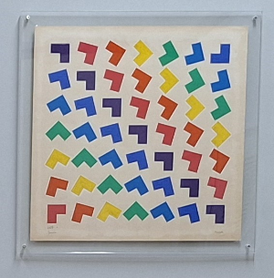
Exhibition [i]Sacilotto em Movimento[/i], Casa do Olhar Luiz Sacilotto, Santo André - SP, on June 22, 2024.[br]Source: The author.
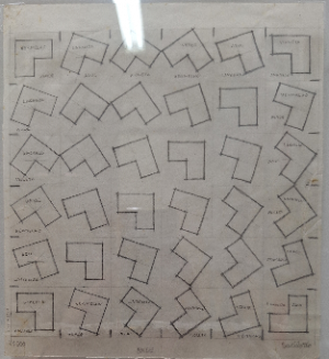
Exhibition [i]Sacilotto em Movimento[/i], Casa do Olhar Luiz Sacilotto, Santo André - SP, on June 22, 2024.[br]Source: The author.
His works frequently feature strict geometric patterns and abstract shapes that interact dynamically, creating illusions of movement. He used lines, polygons, circles, and others, organized precisely, generating compositions that seem to shift positions as the viewer moves. This sense of movement is generated by the repetition and transformation of geometric shapes, which creates a direct connection with the idea of what we call Geometry of Motion. The Geometry of Motion, or Geometry of Transformations, focuses not on the study of plane figures and their properties, but on the movements that such figures can undergo in the plane, without altering their shape or properties. In this geometry, the focus is on isometric transformations: rotation, translation, and reflection.
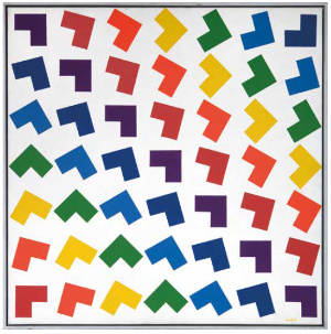
[i]Concreção 9983[/i], 1999[br]Acrylic on canvas[br]70 × 70 cm[br]Private collection, São Paulo[br]Source: Sacilotto, 2021
The presence of the Geometry of Motion is a prominent feature in many of Sacilotto's works. In the specific case of [i]Concreção 9983[/i], we can observe the presence of rotations and translations.[br][br]In previous activities, we used the commands [i]Translate[/i], [i]Reflect[/i], and [i]Rotate[/i], embedding them in button programming to recreate Sacilotto's works. By clicking these buttons, we were able to follow step by step the construction of the reinterpretations. However, this process can be quite tedious and laborious when reproducing an artwork by this artist.[br][br]Sacilotto was meticulous in his calculations, carefully exploring mathematical and geometric properties to compose his works. We have already seen that he used symmetries, repetitions, and geometric transformations precisely to achieve the desired effect. Therefore, recreating some of his works using GeoGebraScript programming not only allows for a visual reinterpretation but also provides a deeper understanding of his creative processes. By using sequences in programming, we can automate transformations such as translations, rotations, and reflections, making it easier to replicate the geometric structures that Sacilotto employed with such precision.
[i]Concreção 9983[/i], 1999[br]Acrylic on canvas[br]70 × 70 cm[br]Private collection, São Paulo[br]Source: Sacilotto, 2021
By carefully analyzing each of the L-shaped forms present in the artwork, it is possible to observe that all of them are representations of an L shape, which we will refer to as the "original form," generated through the application of two isometric transformations: rotation and translation. After applying these transformations to the original form, the images are relocated on a grid, resulting in the composition containing 49 shapes arranged as shown in the artwork.
We will begin the creation of a reinterpretation of the artwork [i]Concreção 9983[/i]. To do this, open a new browser window and access GeoGebra online via the link [url=https://www.geogebra.org/classic?lang=pt_PT]https://www.geogebra.org/classic[/url] .[br][br][list=1][*]First, configure your GeoGebra so that the Algebra Window, the Visualization Window, and the Visualization Window 2 are open, allowing for effective and simultaneous work between them.[/*][*]Add the points A (0,0), B (1,0), C (1, 1), D (-1,1), E (-1,-1), and F (0,1) in the Input field of the Algebra Window.[/*][*]Using the Polygon Toolbar Image button [icon]/images/ggb/toolbar/mode_polygon.png[/icon], create the non-convex hexagon that will represent the original form of the artwork [i]Concreção 9983[/i]. You may choose to remove the labels from points and segments.[/*][/list][br]The following image is a representation of the activity performed so far.
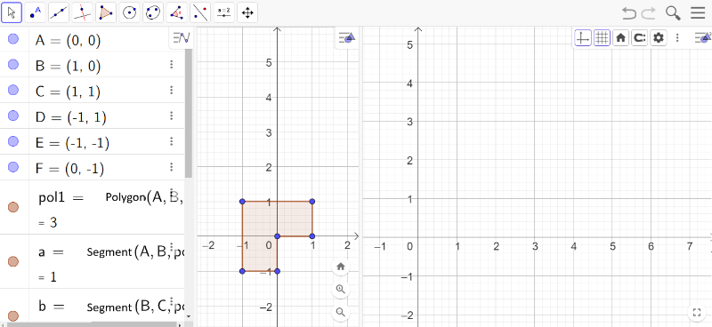
Source: The author.
We will create a grid of points that will be the image of point A, of the Polygon(A,B,C,D,E,F) – referred to as pol1 by GeoGebra – through an isometric transformation. For this, we will use the Sequence command in GeoGebraScript.[br][br]In GeoGebraScript, the Sequence command is used to generate a list of elements following a pattern defined by a mathematical expression. This command is very useful for creating sets of points, geometric objects, or figures based on a repeated formula. The basic structure of this command is:[br][br][code]Sequence(Expression, Variable, Initial Value, Final Value)[br][/code][br]Where:[br][br][list][*][b]Expression[/b]: The formula or object that will be generated at each step of the sequence.[/*][*][b]Variable[/b]: The variable used in the expression that controls the repetition.[/*][*][b]Initial Value[/b]: The initial value of the variable.[/*][*][b]Final Value[/b]: The final value of the variable.[/*][/list]
When creating the points of a grid on the Cartesian plane, it is essential to define the ordered pairs that will represent these points. For the grid required to reinterpret [i]Concreção 9983[/i], taking the origin (0,0) as the first point of the grid, what would be the coordinates of the other points?
The points on the grid would be as follows:[list][*]The first row: (0,1), (0,2), (0,3), (0,4), (0,5), (0,6), all with an ordinate y = 0.[/*][*]The second row: (0,1), (1,1), (2,1), (3,1), (4,1), (5,1), (6,1), all with an ordinate y = 1.[/*][*]Following the pattern of ordered pairs, the last row would be: (0,6), (1,6), (2,6), (3,6), (4,6), (5,6), (6,6), all with an ordinate y = 6.[/*][/list]
When analyzing the ordered pairs presented in the previous question, identify which variable values the abscissas and ordinates of the points can assume.
The abscissas of the points vary from 0 to 6, as do the ordinates.
To create a grid of points on the Cartesian plane using the Sequência command in GeoGebraScript, it is essential to properly define each component of the command. We need to establish the Expression, the Variable, the Initial Value, and the Final Value.[br][br]Let's start by defining the variable [b]i[/b], which will represent the values of the abscissas and ordinates of the points on the grid. In questions 01 and 02, we discussed these values, and each coordinate ranges from 0 to 6.[br][br]Since the grid should contain 49 points, distributed in 7 rows and 7 columns, the expression will be of the form (x(i), y(i)), where x and y depend on the variable i, which is related to the total number of points on the grid.[br][br]We define [b]n = 7[/b] as the number of points in each row or column, resulting in [b]n²[/b] points on the grid. The variable [b]i[/b] should range from [b]0 to 48[/b] (since we want to include the origin as one of the points and avoid points with ordinates equal to 7).[br][br]In fact:[br][list][*]By calculating the remainder of the division of [b]i[/b] by [b]n = 7[/b], we get values ranging from 0 to 6, which will represent the abscissas of the points on the grid.[/*][*]Similarly, by calculating the quotient of the division of [b]i[/b] by [b]n = 7[/b], the values will also range from 0 to 6, representing the ordinates of the points on the grid.[/*][/list][br]To create a grid with 49 points on the Cartesian plane, return to the previous construction and, in the Algebra input field, enter the Sequence command:[br][br][code]L = Sequence((Mod(i,7),Division(i/7)),i,0,48)[br][br][/code]
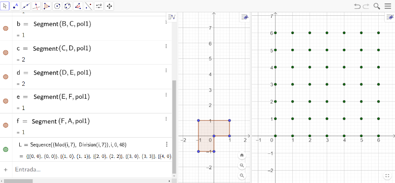
Source: The author.
If the point grid is visible in Viewing Window 1, you can modify its visibility by right-clicking on Sequence L. In the Settings menu, go to the Advanced tab, disable the Viewing Window option, and enable Viewing Window 2. Additionally, you can adjust the window sizes by dragging the edges and resizing them as needed.
After constructing the grid with 49 points, we will use isometric transformations to reinterpret [i]Concreção 9983[/i]. To do this, start by answering the questions that will help you understand the new [b]Sequence[/b] command that will be created.

Source: The author.
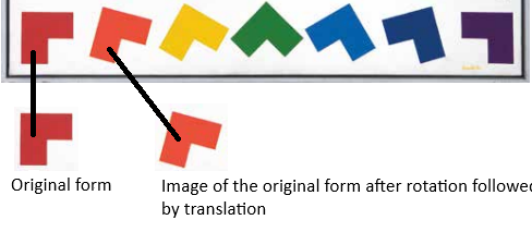
Considering the original shape and the number of shapes arranged in this line, what is the rotation angle, relative to point P, that should be applied to the original shape to generate the subsequent shapes? And in which direction should this rotation occur?
The angle is [math]\frac{90º}{6}=15º[/math][b], [/b]in the clockwise direction.
After rotating the original shape, which isometry should be applied to obtain the 7 shapes present in the line?
The translation is performed along a vector that is positioned horizontally.
Let's start creating a Sequence command that reproduces the 49 shapes composing the artwork as a whole. Among these 49 shapes, one will be designated as the original shape, which, through the application of geometric transformations, will generate 48 additional images that, together with it, will form the complete artwork.[br][br]We will begin with the rotation of the original shape. It is important to remember that the [b]Rotate(Object, Angle, Point)[/b] command is used to rotate the desired object. Thus, we need to apply the command [b]Rotate(pol1, -15°, P)[/b] a total of 48 times.[br][br]However, each of the 48 shapes must be translated in a specific direction, determined by a vector, to each of the points in the grid mesh. Therefore, we must define a sequence that translates the original shape to obtain all the rotated polygons, positioning them at points in the grid mesh.[br][br]We will create another sequence, M, with the following characteristics:[br][br]M = Sequence(Expression, Variable, Initial Value, Final Value)[br][br]where i is the variable with an initial value of 1 and a final value of 49, since there will be 49 shapes in total.[br][br]In the expression, we must apply the translation after rotating the initial shape. The translation should consider the vector given by the direction L(i), where L represents the sequence of points in the grid.[br][br]Thus, we define:[br][br]M = Sequence([b]Translate(pol1, L(i))[/b], i, 1, 49)
Return to the construction started in GeoGebra online and enter the following command in the Input field in the Algebra window:[br][br]M = Sequence[b](Translate(pol1, L(i))[/b], i, 1, 49)[br][br]What do you observe after entering this command? If desired, configure M to appear in Viewing Window 2.
The original shape was translated 49 times so that the image of its point P corresponds to one of the points in the grid mesh.[br][img]data:image/png;base64,iVBORw0KGgoAAAANSUhEUgAAAuUAAAJACAYAAAAq6xijAAAAAXNSR0IArs4c6QAAAARnQU1BAACxjwv8YQUAAAAJcEhZcwAADsMAAA7DAcdvqGQAAP+lSURBVHhe7P17fBTl3f+Pv2ZmD0lIQgI5SAhngihQrEdEUFBs1VYrtWo9tKVVKrYePxaqvVu0/d61P7HaKty2itzaWg9FPFIPaK1orSKHCKIcjUgCSTbZnAh7mMM18/sjM+vuJNnrmtxMk9j38/GYhw/3eu6b3c3MNe+9dnde0ieffGKBIAiCIAiCIIh+Q4rH49SUEwRBEARBEEQ/IElS139jsZglyzJCoZDb6UYymYSoCwCRSASqqmLUqFGpf7A3NE2DZVkIh8PuoW70xQ2FQtzHoOs6TNMUcgGgvb0dbW1tGDVqFAKBgHs4A8MwYBgGwuEwt7bfbigUgizL7uH/E6ZpQlVVhMNhbm3TNKFpmtDj6IsbDAahKIp7uBuqqqKurg5HHXUU8vPz3cMZWJaFZDKJUCjErW1ZFlRVFXocfXEDgQB3f4P9enz22WcoLi5GcXGxezgD5/kFAgEEg0H3cAZeXVVVoSjKEXUdamtrEQ6HUVZWxt3/VVWFJElC85dXF4DQfASPc1JjYyMYYygvL+f+zb3U9cuFPc8wxhAMBrnHbGtrK2KxGMrKyrivn5e6frkAwBiDYRgIBALcY7azsxNtbW0YPnw4hgwZ4h7OwEtdv1zY84au61AUhbvPJRIJRKNRFBQUoKioyD2cgZe6Xl1N04TnDcuyoOs6JEni+rquIxqNQpIkHHXUUe7hDJy6ALjzhl8u0nzTNJGTk+MezoAxhra2NsRiMYwZM8Y9nIFlWaljhVfXi+tgGAZ0XUdubq57qBuOm5OTA8YYEokE2traMHr0aLc66JCdSVaWZe7mxZVlGZqmQdO0brf3tKUeUA9j7s15HJIkdRtzb14es5fHIMsyDMNInbzdY+7Ny+Poy/Pz4rpv721bt24dfv7zn+OTTz7h3s/La+cg8pj74rpv721zmkDLsrqNuTevr7NlWb64oo9Btl+PZDIJ0zS7jfW0idZ1XFHf62MWdWVZhq7rqROWe8y9eant5fmJeum+6H0YY8LPz8v+4Zfr+KKu01CJ7KPO43Df3tPml5vuizxHp0FijHUbc29e6npx5T7s+w7uMfcGu3HVdb3bWE+baF2vrpd9zuvz0zQNhmF0G3Nvfv5NRB+vs3l5PTRN6/e/n1ff7cJ+c+b2BuWWenYEkcYrr7yCZcuWYfv27Vi6dCl27doF0zTdGkEQBEEQRL/hLGx9EaCmnOiG05DPmTMHw4YNw1FHHYW77roLu3btAmPMrRMEQRAEQRD/R6gpJzJwGvJrrrkGZ5xxBsLhMG688UaccMIJ1JgTBEEQBEH4BDXlRIpXXnkFd999NxYtWoTzzz8/44dJN9xwA0444QQsW7aMGnOCIAiCIIgjDDXlBADg5Zdfxt13341rrrkGX//613u8UsANN9yAE088kRpzgiAIgiCII4xy66233uFcfcI0zaybruupK1W4x3raOjo6YBgGioqKYFlWt3F3bdP+9ax7zL2lu7y6hmH44pqmiVgshng8jqFDh0KSpG7j6ZtzWSqR2o6rKIqw66Wu233ppZdwzz33YOHChTjvvPOQm5sL0zRx8OBBVFdX49RTT8XQoUNhmiZOOukk1NXVYc2aNZg4cWLqUnvOVSLctXvaenscPW2O6/yIwz3eV9e0r/rQ1taGgoICBIPBbuPu2rp9GS1ebT9d52pGPNfxW1pakJubi5ycnG7j7k3TtNSv9t1j7s2L6zw/URf2VQncYz1tra2tCAQCGDJkCHdf8jJ/OZcBPNKu6XH+OnToEBhjGDJkCPc1ceYvyb6ij3v83+E6PmNMyD98+DCSySSGDBkCRVG6jfe1LmPMF9d0PQ7ecZhIJBCLxZCbm4tQKNRtPH3zMn/55TqbYRhCx6Gmaejs7EQoFEqdN3rbnMchUtcvN9237B8HusfTN8Mw0NnZCQAoKCjoNu7eROs6rinY8zh1RVzHZ4xxjynGGGKxGDRNQ1FRUbdx9yZa16vr+Ibd97jH3Fu6yxhDMplEIpHAsGHDMNiRotGoJUkS9xqxsC+vJuoCQH19PTRNw5gxY1ITQm84l6YTuaal44pcm9u53NaRdgGgpaUF7e3tGDNmDPdaqs5OJFLbbzf9mt/r1q3D/fffj6uuugrnnHMO8vLyUn51dTUeeeQR3HLLLRg7dmxaJeCPf/wjPvjgA9x44404+uijAfv1E7lOObObS79ckWuJw96fa2trUVFRwb1OuWmaSCaTCIfD3Nqmfc32YDDI3S/8cmG/Hvv27cOwYcO4k5Xl8drj/e061NbWIhQKoaysjLt/eL32uBcXPl6nXNd1HHXUUdzXxJm/0o/v3vDLhcfrfre2tqKzsxNlZWXc6xN7qdvTXNcbXlykLUAEBbIFOjs70draimHDhqGgoMA9nIGXun658Hjd70QigaamJuTn52P48OHu4Qy81PXLhe07CwW841vTNDQ1NUFRFIwYMcI9nIFlWdDsxQpeXceFwLzhxUUfrlMejUaRSCS6nePdWB6uPe7FddB1HYZhcOcB9HCd8lgshvb2dhx77LFuddAhxeNxS5IkoRcukUhA1AWA/fv3Q1VVVFVVcU8+yWQSlmUJ/UFUVU3tcLy6frkA0NTUhGg0iqqqKu5koNvXcs3NzeXWdtycnBzuSeL/6q5fvx6yLOOEE07o9pWVTZs2YeXKlbjtttswbty4jDEAWL58OebPn4/KykoY9jXbc3NzuY/DMIxUo807SfjlAkA8HkdNTQ1Gjx6NoUOHuoczMO1Vr3A4zG2I/XSTySSCwSB3f4P9euzatQvl5eUoLS11D2dgWRYSiYRQbccNBAJCJx8/XIe9e/ciHA5j5MiR3L95IpGALMtCJzYvCxBeXHhcVKirq4Ou66isrOS+Js78JfIG1i8X9jzDGBNqcpuamtDR0YGKiopu848b56Qt8jj8cpHWEAQF3hy3t7ejubkZpaWl3HAdL3W9uM5ihYiLNF9RFO4+F4vF0NDQgIKCApSXl7uHMzDtRQWRun65SGviRY5ZVVVRX18PRVG4wTRe6lp2RoYXF4BQ7+U08aZpcvspxhgaGhoQj8cxadIk93AGTl3GWMbiXU94cR00+3rpvHkAaW5eXh4YYzh8+DDa2tp67FMGG/wZiPhCM2fOHJx++ulCB4Kb66+/HpWVle6bCYIgCIIgCI9QU04QBEEQBEEQ/0c6OjrcN6X45JNPUr9R6A1qygmCIAiCIIgvPFu2bDniW3V1NZh9NbrVq1cjGo26/1n87Gc/w+rVq/GTn/wEL730kns4BTXlBEEQBEEQxBced0N9JDZZlqEoCj788ENs3rwZa9euzfg333vvPUyaNAk/+9nPsGDBAuzbty9jPB1qygmCIAiCIAjCI8XFxTjuuOMAAGvXrsXQodOwYcMG7NixI+WceuqpWLBgAWBftS/bb/GoKScIgiAIgiC+8JxwwglHdJs3bx4A4O9//ztqa2tx1FHnIj+/qttqOQB89NFHeO211zBnzhz3UApqygmCIAiCIIgvPO6m+v+6FRcXo7OzE2vXrkVp6RnIz5+Aiorz8emnn2L9+vWpf7e2thZ//OMf8e1vfzvr5VGpKScIgiAIgiCIPrB27VroOlBRcT4AoKDgaJSUnIa1a9cikUigtrYW//M//4MbbrgBM2fOdN89A6mzs9O3RM+6ujqoqooJEyZwQzKcQA2Ri+N7Cd9wLqJ/pF0AiEajaGlpwfjx47mBK+kJVLzafXFFgi+8uACwefNmrFq1CkuWLOFelJ8xBlVVhUKMnHAKkcfhuCGBlE4vLuwwmX379qGyshKFhYXu4Qyc4J5QKMQN4BgILuzXY8+ePSgtLUVJSYl7OIO+hAeJuqIpnY4rGgICADU1NcjJycGIESO4+5KX+csvFx7nr4MHD0LXdVRUVHBfE2f+Egnt8cuFx/Cg5uZmHDp0CCNGjOCGjHipa3hI6fTiIs0PCiRkdnR0IBqNoqSkhBtQxjwkb/rlwmNCZjweR2NjIwoKCrgBZV7q+uXC9nUPiZ4NDQ2QZRmjRo1yD2fgBOaI1HVcCKR0enFh+86xIhIe1NTUhFgshokTJ7qHM/BS14vroNvhhrx5AK4wRic8qL29nfsc/ODTTz/FXXfdhcrKi1Fe3vVVFgDQtDZ89NHPceaZZ6C9vR1bt25FKBRCQUEBioqKcMstt2TUcZCi0ahvTXl9fT00TcOYMWO4J5/B2JS3tLSgvb0dY8aM4TZJzkQuUttvV/TkU11djUceeQS33HILN4K3L422X25IsClPJpOora1FRUUF8vPz3cMZOA1xWCAt1LQT5kQS9PxyYb8e+/btw7BhwzBs2DD3cAZ9aZ7703Wora1FKBRCWVkZd/9wEvR4J0z0wYXgCRP2PGNZFkKhEPeYbWxshK7rOOqoo7iviTN/iRzffrmw5xnGGILBINdvbW1FZ2cnysrKuCdvL3W9zHVeXHhscjs7O9Ha2ophw4ahoKDAPZyBl7p+ufDY5CYSCTQ1NSE/Px/Dhw93D2fgpa5fLvrQlDc1NUFRFIwYMcI9nMFAa8pNO508G4wxRKNRJBIJ7jnesqzUMcir68V10O1kXd48ANfCJWMMsVgM7e3tOPbYY93qEUfTNNTU1KCmpgbHHnss1qxZg4YGDccc83O3isbGV3Hw4HP42c9+hjFjxriHe0SKx+OWJElCL1wikYCoCwD79++HqqqoqqrinnySySQsyxL6g6h27LPISrJfLuyI6Gg0iqqqKu5kkP7OjlfbcUVWnf1yAWDTpk1YuXIlbrvtNu5KuWEYUFUVubm53NqGYaQabd5Jwi8X9ipPTU0NRo8ezV3FMk0TiUQC4XCY2xD76SaTSQQFVqhhvx67du1CeXk5dxXL8rj6nUgkEAgEhE4+frgOe/fuRTgcxsiRI7l/80QiAVmWhU5sXhYgvLjwuKhQV1cHXddRWVnJfU2c+UvkDaxfLjyuaDc1NaGjowMVFRXcVGHnpC3yOPxykdYQBAXeHLe3t6O5uRmlpaVZv0cKj3W9uM5ihYiLNF8R+MQqFouhoaEBBQUFKC8vdw9nYNqLCiJ1/XKR1sSLHLOqqqK+vh6KomD06NHu4Qy81LUsK/XGX9QFINR7OU28aZrcfooxhoaGBsTjcUyaNMk9nIFTlzHGXc324jpomgZd17nzANLcvLw8MHulvK2tjdun/F9obW3F6tWr8fHHH6feJDU1NaGurg7Dh4/B7Nm3o6zsS+67YceOX2LixOG47rrr3EM9wp+BCIIgCIIgCGKQ477GeG/bJ598knoz9P777+O2225Da6uGY4+9CMce+1Mcf/wDOHjwIMrKTkEy2Yq1axdi69b73f8cRow4H9u3b8emTZvcQz1CTTlBEARBEATxhcfdfPe2OZ+qbt26Ff/7v/+LKVO+ipKSG6Aoc5CbOx6vv34dgACGDbsNEya8ieLio7Fx45+xe/fTGf9ecfHxKCo6rsdLJPYENeUEQRAEQRAEAWDMmDEYN24c4vE4nn76aYwbdwJycr6ZGo9Gt+GzzzZhxIibEAp1BQFVVPwZJSVfwubNDyKZbE2r1nVVlkgkgpdeeinj9p6gppwgCIIgCIL4wuO+znhP23HHHQdJkrB161YUFpZg2LAfZtR46607EAgUYvjwSzJuLym5BbFYOz788OGM23NzK1Fe/hWsXbsWLS0tGWNuqCknCIIgCIIgvvC4G/CeNudHy5999hmCwcwfaO/duxotLXUYMeJmxGJbMjZdT2L48LGor6+GqkYzttLSMxAIFOLFF1/MqOeGmnKCIAiCIAiCSGPHjh1QlMwMkw0bHgAA1NX9EjU113TbWlo+QyIRwUcf/Ve3Tdc7sGHDBuzcuTOjZjrUlBMEQRAEQRBEGl2XSLVS///ZZ69i5sybcNZZP+91mz37qzj55JPx//7f/+t1y3bp1d5HCIIgCIIgCOI/kGnTpsEwOlL/P3bsOZgw4cKsW35+DmbPno2jjz4669Ybyq233nqHZVmQZRmmaWbddF2HqGuaJjo6OmAYBoqKimBZVrdxd23TNIVqp7u8uoZh+OKapolYLIZ4PI6hQ4dCkqRu4+kbYwyGYQjVdlxFUYRdL3VFXNM0cfDgQVRXV+PUU0/F0KFDu427a+u6LlTby+NwXCdkxT3eV9e0gx7a2tpQUFCAYDDYbdxdW7dT4Hi1/XQ1TUu9y3aPuzfGGFpaWpCbm4ucnJxu4+7NCb7g7cteXef5iboAhFzTNNHa2opAIIAhQ4Zw9yUv85dmp24eadf0OH8dOnQIjDEMGTKE+5o485ckSdy6frmOzxgT8g8fPoxkMokhQ4ZAUZRu432tyxjzxTVdj4N3HCYSCcRiMeTm5iIUCnUbT9+8zF9+uc5mGIbQcahpGjo7OxEKhZCbm9ttPH1zHodIXb/cdN+yLK5vGAY6OzsBAAUFBd3G3ZtoXcc1BXsep66I6/iMMe4xxew0TE3TUFRU1G3cvYnW9eo6vmH3Pe4x95buMsaQTCaRSCS4ydVeSSaT2LZtC4YNOwGmyQ+mys3dj507X8KZZ57JTYDtDSkajVqSQKoU+pBcV19fD03TMGbMmNSE0BtOyp1IYpWXRDwn2epIuwDQ0tKC9vZ2jBkzhpuU5uxEIrX9dkWS9gCguroajzzyCG655RZuBC+zG0aRVDy/3VAoxE13hL0/19bWoqKiAvn5+e7hDEw7TTMskBZq2glzIgl6frmwX499+/Zh2LBh3MnK8hBxPxBch9raWoRCIZSVlXH3DydBTyT1z6sLwQhs2POMZVkIhULcY7axsRG6ruOoo47ivibO/CVyfPvlwp5nGGMIBoNcv7W1FZ2dnSgrK+OmD3qp62Wu8+LCY2x9Z2cnWltbMWzYMBQUFLiHM/BS1y8XacmUikBsfSKRQFNTE/Lz8zF8+HD3cAZe6vrlwvadhQLe8a1pGpqamqAoCrfJsuwUS5G6jguBecOLC9t33vjz+inGGKLRKBKJBPccb1lW6hjk1fXiOuh2si5vHkBaom1OTg6Y/caivb0dxx57rFvtxpYtW9w3daOgoADjx49HIBDAb3/7WyQSCkaOvBn2e78eCQaBxsblqKgoxPe+9z33sDBSPB63JEkSeuESiQREXQDYv38/VFVFVVUV9+STTCZhWZbQH0S1Y59zcnK4df1yYUesRqNRVFVVcScD3Y64z83N5dZ23JycHO5Jwi8XADZt2oSVK1fitttu48bXGoYBVVWRm5vLrW0YRqrR5p0k/HIBIB6Po6amBqNHj8bQoUPdwxmY9qpXOBzmNsR+uslkEsFgkLu/wX49du3ahfLycpSWlrqHM7DsiHuR2o4bCASETj5+uA579+5FOBzGyJEjuX/zRCIB2Q6E4OFlAcKLC4+LCnV1ddB1HZWVldzXxJm/RN7A+uXCnmcYY0JNblNTEzo6OlBRUcGN13ZO2iKPwy8XHiPu29vb0dzcjNLSUhQVZV7FwY2Xul5cZ7FCxEWarwjE1sdiMTQ0NKCgoCB1xYreMO1FBZG6frlIa+JFjllVVVFfXw9FUTB69Gj3cAZe6lqWlXrjL+oCEOq9nCbeNE1uP8UYQ0NDA+LxOCZNmuQezsCpyxhDXl6eezgDL66DpmnQdZ07DyDNzcvLA2MMhw8fRltbG7dPAYCHHnrIfVOPzJo1C8ceeywOHTqExYsX47jjvopA4JuwPv+KeYqCAuDgwYewd+8W/P73v+e+7tngz0AEQRAEQRAE8R/C3r170djYiMLCQvz3f/839u3bgLa2+xEKrUco9CmKioC8vE8RCPwdmzYtRkvLPtx+++3/p4Yc1JQTBEEQBEEQ/wm4r0ne21ZZWYnOzk7EYjGUlpbil7/8JYYODWPnzlfw3nt34Y03rsE//3kXPvvsbZx88gn4zW9+g4qKCvc/5xlqyr8AyLLM/RicIAiCIAjiPxl3851tq6qqSn2dJjc3F9dccw3uuusuLFu2DLfccgvuuece/OpXv8K3v/1t9z/TZ6gpH+TIsoxQKATDMPDmm2/iBz/4AaZNm4apU6fiBz/4Ad555x0kk0nA/mU6QRAEQRAE0TeGDh2KSZMmcS8Q0ReoKR/kyLIMVVXxu9/9Dj/5yU9w4MABfOtb38LFF1+Mffv2YdGiRXjkkUfQ0dFBK+oEQRAEQRADFGrKBzmSJOHvf/87nn/+eZx88slYuXIlfvGLX+D222/Ho48+ihNOOAFPPvkkqqurU7+op8acIAiCIAhiYEFN+SBH0zTs3LkTsizjggsuQHl5eeqyXmPGjMF5550HXdfx8ccfQ1VVoUt+EQRBEARBEP9eqEMb5Jh2wlVBQQEKCgq6Nd3FxcUIBAJoamqCkZbqRhAEQRAEMdiR7DTeLwJSJBKxAAhddN9JlRJxASASiUDXdYwcOZLbDHqp7Zer2zHcwWCQ+3hhB0N0dHRg5MiR3FAGJ90qJJDix+wY4GyuLMvIycmBoih48MEH8cgjj+DGG2/E/PnzU+FHlmXh4YcfxqpVq3Dttdfi4osvRiAQSIWX8KiursZjjz2Gm266CWPGjHEPZ+CkxokEhgwEF2nBEGVlZdzAAifAQSQVz09X0zQEAgGuC/v1qKurQ1FRETe4xKmtKAp3Xx4IrsOBAwcQCoVQUlLC/ZtrdrAHLxwJPrrwOM80NzfDMAyUlpZyXxMvdf1yYc91pmkiEAhw/yZtbW2IxWIoKSnhBqN4qevMt0HB9E9RF2nzs8hxePjwYbS3t6OoqIj7ozAvdf1yYS/0GIYBWZa5+1wymURLSwvy8vJQXFzsHs7AS10vrmUnWIoeg158XdcRjUahKArKysrcwxl4qeuXC9t3jhVeMJFpmmhtbUUikcCoUaPcw91wjhVeXXh0YfuGYXDnAaS54XAYjDEkk0kcPnwYkydPdquDDmnLli2WJEnCk5GoC/uANU1TKNHJNE1YliU8afS3C1eqFO9k5aW2iCvLMsrKyjB8+HAcPHgQv/jFL9DY2Iibb74ZZ5xxBhRFwauvvop77rkHI0eOxB133IHx48ejpaUF0WgUjDF3yW7s3LkTzz//PL73ve9xr79pWRZM04Qs8GPSgeDC3p8TiQRycnKEJn7R2gPBhe3H43GEQiHuZO6ldl9ckXnDi+vgpAyLpGOapgnYxw4Pv1x49JN20rFI2qRpzxsifxe/XNh/R8uyIEkS19c0LXVyzTbfwWNdv1x43P8NO2U4FAoNijkGHn3mIf3TS92+uJKHeUP0GDTtlE4IpmmK1kUfXIvTE6Qj6lv2opDZz30a0v6OIn76/uE8h1gshtmzZ3P3w4GOFI/HLUmShHY45wQo4gLA/v37oaoqqqqquAeWc/IRSUNydiJnRTgbfrmwI6Kj0Siqqqq4TY9uR9zn5uZyaztuTk4O94C17JPJwYMHsWLFCrzyyiuIx+Op8YsuugjXXXcdRowYAUmSoKqq8Erypk2bsHLlStx2223c+FrDMKCqKnJzc7m1nROVyInYLxcA4vE4ampqMHr0aAwdOtQ9nIFpmkgkEgiHw9yTq59uMplEMBjk7m+wX49du3ahvLwcpaWl7uEMLDviXqS24wYCAe4E6JfrsHfvXoTDYYwcOZL7N08kEpBlWWjlJplMQhKIwIZHF/Y8Y9mNNm8uqKurg67rqKys5L4mzvwl0sD75cKev5j9qSDPb2pqQkdHByoqKrifVum6nmrgeXX9cuEx4r69vR3Nzc0oLS3lflrlpa4X12mcRVx4bLRjsRgaGhpQUFCA8vJy93AGpmlCVVWhun65SGu0RY5Z1f40VVEUjB492j2cgZe6TiPpxYXgGwPL/sTRNE1uP8UYQ0NDA+LxOCZNmuQezsCpyxjjNvBeXAdnkZM3D8C1IGpZFpLJJNrb25GXl8c9zgY6/BmIGNBIkoRIJIIHH3wQr776KkaOHIkrr7wSV155JcaOHYuXX34ZTzzxBFpaWlINPK8RIAiCIAiCGMg4/YyiKMjJyUE8Hoeu625tUEFN+SCns7MTv/vd7/DSSy9h4cKFeOKJJ7B06VIsXboUzz//PK644go89dRTWLlyJdra2oRWSgiCIAiCIAYDiqKkPulqb28f1I05NeWDnN27d2Pjxo2YOXMmvvGNb6CwsDA1lpeXh+985zuYNm0aNm7ciLq6Opj2d+8IgiAIgiAGM85KeSgUQl5eHjRNQ3NzM9rb24V+OzfQoKZ8kNPS0gJVVTF58mQUFBR0a7iHDRuGY445BtFoFAcPHoRhGBnjBEEQBEEQgxnnKyyFhYUIBoOIxWI4cOAAtm7ditdffx379u3jbnv37sWOHTu63d7T5sXdt28fampq8NFHH3W7PX377LPPqCn/ouD8UJYgCIIgCOI/Bee75YFAALm5uSgsLERxcTGGDRuGoqIiFBQUoKSkhLsNHz4cw4cP73Z7T9vw4cMxbNiwbrf3ton4w4cPp6Z8sDNixAjk5OTgo48+QltbG0z7MksOhw4dQk1NDYYNG4aKigr6TjlBEARBEF8oJPuSmIqiIBgMIicnB7m5ucjJyUEoFEJubq7Q5txPZPPiivrUlA9yJkyYgFmzZmH79u144YUX0NHRkRqLx+N45JFHsGXLFsyYMQOjR4/mXjaOIAiCIAhiMOI0585/nU1RlEGxUVM+yBkyZAgWLlyIk08+GQ8//DAuvfRS/PKXv8RvfvMbXHzxxXj00Ucxc+ZMXHHFFSguLoZpX9CfIAiCIAjii4jzlZbBtlFTPsixLAuVlZW49957cccdd6CkpARPP/00Hn/8cRQWFuLXv/41/r//7/9LBR8YhkFNOUEQBEEQxABD6uzstCSBVCn0Ibmurq4OqqpiwoQJkDiX4XNS7kQSq7wk4jnJVkfaBYBoNIqWlhaMHz+em4LoJLCJpIV6cU07llbhfC3FSdhyEi9Fkus2b96MVatWYcmSJdxET8YYVFUVSiF1EuNEHofjhkIh7nP04sJOeNy3bx8qKyszLiXZE06aZkggLnsguLBfjz179qC0tBQlJSXu4QycNE0viZ6ibjKZRCAQEHYVwWQ+AKipqUFOTg5GjBjB3Ze8zF9+ufA4fx08eBC6rqOiooL7mjjzl0iSpl8uPCZ6Njc349ChQxgxYgQ3+c9LXcMwYBjGEXeR5geDQe4809HRgWg0ipKSEm5qMGMsldLJq+uXi7RkSsX+bm424vE4GhsbUVBQwE0N9lLXLxe2r+s6JEkSOqYaGhogyzJGjRrlHs7AOceK1HVcANx5w4sL23eOlVyBRM+mpibEYjFMnDjRPZyBl7peXAfdTjLnzQPw4FqWhZaWFjQ2NmLq1Knu4W4YdjK5SKqoFxf2ax2Px1FQUOAeykCKRCKWyE4E+2Qi6gJAJBKBpmmorKzknnw0TUudqHj0xQ2FQtzHoOt66uTDcwGgra0NHR0dqKys5DZJzkQuciL26pqmifz8/NSk69zHNE2YpgnDjp9PP6nx6gJAdXU1HnvsMdx0000YM2aMezgDZ+IXObENBBf2/nzgwAGUl5cjPz/fPZyB0zCGBBp+y45FFjkJ9sUNBALc/Q3261FbW4vi4mJu9LCX2n66zsmV5zocOHAAwWAQpaWl3L+5c8IUOXF7dQEIz4uOHwwGucdhJBKBYRgoKyvjPhYv85dfLtLmpEAgwP2btLW14fDhwygpKeGevL3UNQwDjDEEg8Ej6sI+rgzDQCAQ4B6zhw8fRltbG4qLi7lzjJe6frlIa1pFjsNkMoloNIohQ4aguLjYPZyBl7p9cWVZ5h4jSGsYRY5vXdcRjUYhyzLKy8vdwxk4dSEwF/jlwvadY4XXIzHG0NraimQyKfSmQ7SuF9fB6XtEFmZFXcuyUm+MeW86kLYgypuL4NGFvZ8mEgluEy/F43FLkiTuk4O9sijqAsD+/fuhqiqqqqq4k7lzST+RJ6iqKkzTFFpJ9ssFgKamJkSjUVRVVQkd3M4fkFfbcUVWnf1yAWDTpk1YuXIlbrvtNu5KuWG/a8zNzeXWNuw3CeFwmHuS8MuFvcpTU1OD0aNHc1exnAMqHA4LnST8cpPJJIICK9SwX49du3ahvLycu4pleVz9TiQSCAQC3JOEX67D3r17EQ6HMXLkSO7fPJFIQJZloZOEl9VvLy48rpTX1dVB13VUVlZyXxNn/goLfALllwuPK9pNTU3o6OhARUUF92Sl6zoMe7GCV9cvF2kn42AwyD1m29vb0dzcjNLSUu4bYy91vbjM/gRRxEWarwh8YhWLxdDQ0ICCggJu02qaJlRVFarrl4u0lXWRY1ZVVdTX10NRlNRXQHvDS11nscKLC0Co97LsxQ3TNLn9FGMMDQ0NiMfjmDRpkns4A6cuY0xohVrUdXAWDnnzADy4lmUhGo2ivr4e06dPdw93Q9d1aJrGrQvbVVWV+2bbgTGGWCzG/VSePwMRBEEQBEEQBOEr1JQTBEEQBEEQRD9DTTlBEARBEARB9DPUlBMEQRAEQRBEP0NNOUEQBEEQBEH0M9SUEwRBEARBEEQ/Q005QRAEQRAEQfQz1JQTBEEQBEEQRD8jdXZ2WiIXsEcfQjLq6uqgqiomTJjADclwAjVELo7vJXzDuYj+kXYBIBqNoqWlBePHj+cGrjhhDyLBRH1xRYIvvLgAsHnzZqxatQpLlizhhgcxxqCqqlAwkRNOIfI4HDckkKTpxYUdJrNv3z5UVlZyL+jvBPeEBCLuB4IL+/XYs2cPSktLUVJS4h7OoC/hQaJuMplEIBAQdkVDQACgpqYGOTk5GDFiBHdf8jJ/+eXC4/x18OBB6LqOiooK7mvizF8ioT1+ufAYHtTc3IxDhw5hxIgR3JARL3UNO/HvSLtI84MCKbxOmmBJSQk3oIzZicQidf1ykRaCowjE1sfjcTQ2NqKgoIAbUOalrl8ubF+3Ez1FjqmGhgbIsiyUeKnZ4UG8uo4LgDtveHFh+86xIhIe1NTUhFgsxk289FLXi+ug2+GGvHkAHlzLstDS0oLGxkZMnTrVPdwNww5BFAkP8uLCfq3j8TgKCgrcQxlIkUjEEtmJYJ9MRF3YEdGapqGyspJ78tE0LXWi4tEXNyQQEa17jJNua2tDR0cHKisruU2SM5GLnIj9dJ2TGs8FgOrqajz22GO46aabMGbMGPdwBs7EL3JiGwgu7P35wIEDKC8v56ZyOQ1jSKDht+wENpGTYF/cgEBkPezXo7a2FsXFxdw0QS+1/XSdkyvPdThw4ACCwSBKS0u5f3PnhCly4vbqQjACG2l+MBjkHoeRSASGYaCsrIz7WLzMX365sOcZ0zQRCAS4f5O2tjYcPnwYJSUl3JO3l7rOXBcMBo+oC/u4MgRj6w8fPoy2tjYUFxdz5xgvdf1ykda0ihyHyWQS0WgUQ4YMQXFxsXs4Ay91++LKssw9RpDWMIoc37quIxqNQpZlbmKpUxcCc4FfLmzfOVZ4PRJjDK2trUgmk0JvOkTrenEdnF5GZGFW1LUsK/XGmPemA2kLl7y5CB5d2PtpIpHgNvFSPB63JEniPjnYK4uiLgDs378fqqqiqqqKO5knk0lYliX0BFU79llkJdkvF3ZEdDQaRVVVldDB7fwBebUdV2TV2S8XADZt2oSVK1fitttu466UG/a7xtzcXG5twzCg2SvlvJOEXy7sVZ6amhqMHj2au4rlHFDhcFjoJOGXm0wmERRYoYb9euzatQvl5eXcVSzL4+p3IpFAIBDgniT8ch327t2LcDiMkSNHcv/miUQCsiwLnSS8rH57ceFxpbyurg66rqOyspL7mjjzV1jgEyi/XHhc0W5qakJHRwcqKiq4Jytd12HYCxC8un65SDsZBwVi69vb29Hc3IzS0lLuG2Mvdb24zP4EUcRFmq8IfGIVi8XQ0NCAgoICbtNqmiZUVRWq65eLtJV1kWNWVVXU19dDURSMHj3aPZyBl7rOYoUXF4BQ72XZixumaXL7KcYYGhoaEI/HMWnSJPdwBk5dxpjQCrWo66BpGnRd584D8OBaloVoNIr6+npMnz7dPdwNXdehaRq3LmxXVVXum20HxhhisRj3U3n+DEQQBEEQBEEQhK9QU04QBEEQBEEQ/Qw15QRBEARBEATRz1BTThAEQRAEQRD9DDXlBEEQBEEQBNHPUFNOEARBEARBEP0MNeUEQRAEQRAE0c9QU04QBEEQBEEQ/YzU2dlpiVzAHn0Iyairq4OqqpgwYQI3JMMJ1BC5OL6X8A3nIvpH2gWAaDSKlpYWjB8/nhu44oQ9iAQT9cUVCb7w4gLA5s2bsWrVKixZsoQbHsQYg6qqQsFETjiFyONw3JBAkqYXF3aYzL59+1BZWcm9oL8T3BMSiLgfCC7s12PPnj0oLS1FSUmJeziDvoQHibrJZBKBQEDYFQ0BAYCamhrk5ORgxIgR3H3Jy/zllwuP89fBgweh6zoqKiq4r4kzf4mE9vjlwmN4UHNzMw4dOoQRI0ZwQ0a81DXsxL8j7SLNDwqk8DppgiUlJdyAMmYnEovU9ctFWgiOIhBbH4/H0djYiIKCAm5AmZe6frmwfd1O9BQ5phoaGiDLslDipWaHB/HqOi4A7rzhxYXtO8eKSHhQU1MTYrEYN/HSS10vroNuhxvy5gF4cC3LQktLCxobGzF16lT3cDcMOwRRJDzIiwv7tY7H4ygoKHAPZSBFIhFLZCeCfTIRdWFHRGuahsrKSu7JR9O01ImKR1/ckEBEtO4xTrqtrQ0dHR2orKzkNknORC5yIvbTdU5qPBcAqqur8dhjj+Gmm27CmDFj3MMZOBO/yIltILiw9+cDBw6gvLycm8rlNIwhgYbfshPYRE6CfXEDApH1sF+P2tpaFBcXc9MEvdT203VOrjzX4cCBAwgGgygtLeX+zZ0TpsiJ26sLwQhspPnBYJB7HEYiERiGgbKyMu5j8TJ/+eXCnmdM00QgEOD+Tdra2nD48GGUlJRwT95e6jpzXTAYPKIu7OPKEIytP3z4MNra2lBcXMydY7zU9ctFWtMqchwmk0lEo1EMGTIExcXF7uEMvNTtiyvLMvcYQVrDKHJ867qOaDQKWZa5iaVOXQjMBX65sH3nWOH1SIwxtLa2IplMCr3pEK3rxXVwehmRhVlR17Ks1Btj3psOpC1c8uYieHRh76eJRILbxEvxeNySJIn75GCvLIq6ALB//36oqoqqqiruZJ5MJmFZltATVO3YZ5GVZL9c2BHR0WgUVVVVQge38wfk1XZckVVnv1wA2LRpE1auXInbbruNu1Ju2O8ac3NzubUNw4Bmr5TzThJ+ubBXeWpqajB69GjuKpZzQIXDYaGThF9uMplEUGCFGvbrsWvXLpSXl3NXsSyPq9+JRAKBQIB7kvDLddi7dy/C4TBGjhzJ/ZsnEgnIsix0kvCy+u3FhceV8rq6Oui6jsrKSu5r4sxfYYFPoPxy4XFFu6mpCR0dHaioqOCerHRdh2EvQPDq+uUi7WQcFIitb29vR3NzM0pLS7lvjL3U9eIy+xNEERdpviLwiVUsFkNDQwMKCgq4TatpmlBVVaiuXy7SVtZFjllVVVFfXw9FUTB69Gj3cAZe6jqLFV5cAEK9l2Uvbpimye2nGGNoaGhAPB7HpEmT3MMZOHUZY0Ir1KKug6Zp0HWdOw/Ag2tZFqLRKOrr6zF9+nT3cDd0XYemady6sF1VVblvth0YY4jFYtxP5fkzEEEQBEEQBEEQvkJNOUEQBEEQBEH0M9SUEwRBEARBEEQ/Q005QRAEQRAEQfQz1JQTBEEQBEEQRD9DTTlBEARBEARB9DPUlBMEQRAEQRBEP0NNOUEQBEEQBEH0M1JnZ6clcgF79CEko66uDqqqYsKECdyQDCdQQ+Ti+F7CN5yL6B9pFwCi0ShaWlowfvx4buCKE/YgEkzUF1ck+MKLCwCbN2/GqlWrsGTJEm54EGMMqqoKBRM54RQij8NxQwJJml5c2GEy+/btQ2VlJfeC/k5wT0gg4n4guLBfjz179qC0tBQlJSXu4Qz6Eh4k6iaTSQQCAWFXNAQEAGpqapCTk4MRI0Zw9yUv85dfLjzOXwcPHoSu66ioqOC+Js78JRLa45cLj+FBzc3NOHToEEaMGMENGfFS17AT/460izQ/KJDC66QJlpSUcAPKmJ1ILFLXLxdpITiKQGx9PB5HY2MjCgoKuAFlXur65cL2dTvRU+SYamhogCzLQomXmh0exKvruAC484YXF7bvHCsi4UFNTU2IxWLcxEsvdb24DrodbsibB+DBtSwLLS0taGxsxNSpU93D3TDsEESR8CAvLuzXOh6Po6CgwD2UgRSJRCyRnQj2yUTUhR0RrWkaKisruScfTdNSJyoefXFDAhHRusc46ba2NnR0dKCyspLbJDkTuciJ2E/XOanxXACorq7GY489hptuugljxoxxD2fgTPwiJ7aB4MLenw8cOIDy8nJuKpfTMIYEGn7LTmATOQn2xQ0IRNbDfj1qa2tRXFzMTRP0UttP1zm58lyHAwcOIBgMorS0lPs3d06YIidury4EI7CR5geDQe5xGIlEYBgGysrKuI/Fy/zllwt7njFNE4FAgPs3aWtrw+HDh1FSUsI9eXup68x1wWDwiLqwjytDMLb+8OHDaGtrQ3FxMXeO8VLXLxdpTavIcZhMJhGNRjFkyBAUFxe7hzPwUrcvrizL3GMEaQ2jyPGt6zqi0ShkWeYmljp1ITAX+OXC9p1jhdcjMcbQ2tqKZDIp9KZDtK4X18HpZUQWZkVdy7JSb4x5bzqQtnDJm4vg0YW9nyYSCW4TL8XjcUuSJO6Tg72yKOoCwP79+6GqKqqqqriTeTKZhGVZQk9QtWOfRVaS/XJhR0RHo1FUVVUJHdzOH5BX23FFVp39cgFg06ZNWLlyJW677TbuSrlhv2vMzc3l1jYMA5q9Us47Sfjlwl7lqampwejRo7mrWM4BFQ6HhU4SfrnJZBJBgRVq2K/Hrl27UF5ezl3FsjyuficSCQQCAe5Jwi/XYe/evQiHwxg5ciT3b55IJCDLstBJwsvqtxcXHlfK6+rqoOs6Kisrua+JM3+FBT6B8suFxxXtpqYmdHR0oKKignuy0nUdhr0Awavrl4u0k3FQILa+vb0dzc3NKC0t5b4x9lLXi8vsTxBFXKT5isAnVrFYDA0NDSgoKOA2raZpQlVVobp+uUhbWRc5ZlVVRX19PRRFwejRo93DGXip6yxWeHEBCPVelr24YZomt59ijKGhoQHxeByTJk1yD2fg1GWMCa1Qi7oOmqZB13XuPAAPrmVZiEajqK+vx/Tp093D3dB1HZqmcevCdlVV5b7ZdmCMIRaLcT+V589ABEEQBEEQBEH4CjXlBEEQBEEQBNHPUFM+yAkEAsjLyxP62DVgf6+X95E5QRAEQRAE8e+F38kRA5rt27djzpw5mDRpEnd77rnnoNs/cCEIgiAIgiAGDtSU/4eQn5+PIUOGcH8MRxAEQRAEQfz7oaZ8kPOlL30J69evx549e7ptO3fuxC233ILhw4dj4cKFmDFjBveX3gRBEARBEMS/H2rKv8CsX78eTz31FE455RRccMEFKCwshGVZsCzLrRIEQRAEQRD9CDXlgxwnMMfdaDc0NODJJ59EXl4eLrvsMpSVlQH2tTUJgiAIgiCIgYUUiUQsCCZFeU2ui0Qi0HUdI0eO5P640Ettv1ynuRVJ2gOANZvWYFvtNuQN4V/9xDRNmKYJRVG4tfvsyhICdtpddXU1qqurMXXqVHz5y19GTk4ODL0rXEeWZW5dANi8dzN2fLYDFSMruKEFlmnBtEyh2gPBBYC4GkcsGcPQvKEIBbPvHxYsWKYFSZK4tQeCCwAxNYZ4Mo6C3ALkhDh/Pw+1B4ILAKZlou1wG0KBEApyCgDOXUzTFK/tkwvbhwTIUvY5wzANtMfaoUgKioYUces7n4JJsgSJ82L45SLdF3hNOuId0AwNw/OHc+dQL3X9cuH4pv16cHzGGIrCRThmxDH8OcayYJpi85dfLhzf6tqnufuoYaBAKcB5U8/DxJHZExNN04RhGJBlmRti5MW1PCR0wqOv24meiqKkFrZ6w0tdv1zYviGYpmmaJlpbW5FIJLiJnkhLv+XVhUcXHlI64cG1LAuHDh1CNBrFhAkT3MPdcEK5eKFL8OjCfq2TySQ3TElav349fZehDzz64aNYvXM14nrcPUQQBEEQ/xHkBHJw5tgzsWTGEvcQQRAekeLxuCVJEvcdB+yYalEXAPbv3w9VVVFVVcV9h55MJmFZltC7Dif2OScnh1vXL/eSBy/Bi1tfhGp0xd8SBEEQxH8i5049Fy/f+LL75gxM04SqqlAUhfvJtV8ubF/TNEgCEfeqqqK+vh6KomD06NHu4Qy81LUsC6qqenIBCPVelh1xb5omt59ijKGhoQHxeByTJk1yD2fg1GWMcVd7vbgOmqZB13WhiHtR17IsRKNR1NfXY/r06e7hbui6Dk3TuHVhu6qqIj8/3z3UI4wxxGIxFBYWuocyoKY8DS9uelP+4HceREl+iVvJwPkoJxQKcWszxmAYRp/c1rZW/OUvf0EinsCll16KUaNGpS6DyBiDwQyEgvy6r+14DX/d9Fe0x9vxvVO/h7LC7B/dmaYJxphQOJHfrqIo3I/C3615Fx/UfoC4Fseco+dg2shpyAn2vl9blgXd0BFQur4elA2vrmEYQo/Zi9tyuAV/3/l31LbWomJoBeZMnoORRSPdWgovtR1XlmXuJTb9cttibVi/Zz0+afoEZQVlOH3S6RhXMs6tZWAYBiABASX7x+Hw0YXjA1ACStavg7zzyTt4r+Y9BJUgTpt4Gk4ae5JbyYAxBtMyEVD4x4pfLmzfsizu1++27N+Cf+z6BwJyACeOPRGzq2a7lQxE68KeC8y+fAWQ4yLNl2U567FyoO0A1u9ej4aOBpw+6XTceNaNbiUDZnbN5QElwN3//XLh4asj+6L7sOqdVdjZsJOaco91nUbbiwtqylOIuhY15Zn8pzTlm3++GRVFFW4lA0M3oBu6UO2+uOFwGLIs4/XXX8fy5ctx5plnYsGCBSgqKurVzcZj7z2Ge167B02dTfjF+b/AOVPOQV6o94OLMQZd0xEKh7i1fXdDIchKdvfe1+7FC1tfwKHkIVx84sX4wWk/wFFDj3JrKSzLQjKZRCgU4p7YnEk0GAz64jrJrNl4Z+87WPHmCuxu3I3xJeNx63m3Zm3qvNTui6soCvf7kF7cTZ9twgNvPoCtdVsxetho3DTvJsydPNetZaCqKmRJRjCUvTb64EqSJNQQIO13Lrzfrjyw/gGsfHslQoEQrj3jWiw4bYFbyUDXdZimKfRm3i8X9psOk5kIBLO/KX38/cfx23W/RVAJ4soZV+KGs25wKxmI1kXaIkgwGDyiLpzFDd1AIJi9yd3w6QYse3UZ9kX34aLjL8Lyy5e7lQyc+SsYDEIJ9F4XPrpIay55x2F1bTUWP72YmnIbL3WpKe+OaKMND+5gbMr5MxAx4JHsHyglk0l8+OGHAICpU6dyD0iCIAiCIAhiYEBN+RcA5xfyLS0tqKmpQWVlJcaOHZt1lYMgCIIgCIIYOFBT/gVAkrs+Uj5w4ADq6+sxZswYDBs2TOijWIIgCIIgCKL/oa7tC4DzPc+aT2qgqirGjh3L/Z4aQRAEQRAEMXCgpnywI3U15ZqmIdoSRTAYRGlJKfcHeARBEARBEMTAgZryLwCSJEFTNTQ1NWHIkCEoHFpIX10hCIIgCIIYRFDnNshxvrqSVJOIxWJdTXlBIRSZf+krgiAIgiAIYmBATfkgx7IsmKaJkpIS/O53v8PDDz+MSUdP4l6nmyAIgiAIghg4SJFIxBINvvAakhGJRKBpGiorK7mhE5qmwbIsoR8o9sUVCb7wEpKx4M8L8MqOV6AaKtbftB5HFfYePAOfEz0ty8KQIUNSl0BkjEG1g5DcrhOSwav71JansOKtFYgejmLJV5Zg3tHzkBvs/brnpmnC0I2u2vbVYHrDcUVCQPxyV7y1Ai9/9DI61U7Mnz4fV5x8BcoLyt1aCsuyoGs6AoEA9w2P364SULKGlgDAhn0b8NA7D2Fv816MHTYWN591M44fdbxbS+GltmVZMHQDssJP3uyTK8vckJPqumqs+tcqfFj/ISqLKvGj03+E2ROzJ0Lqug5Z4teGHbQFAIEg/7cZXlyk+4EAsgR64uF3H8afNvwJISWEq2ZehctPutytZGAYBizTQiDIT970ywUAZtgJoJwU3qern8b96+9HUAnikuMvwaLZi9xKBowxmCa/LhzXDho6ki4AmKwrOZi3T2/avwn3vXkf9rfuxwXTLsCy+cvcSgamnaSpKPxj0C8XaT4v0XPbwW1YunYpdjftxrzJ87Dm6jVuJQPTNKHrOhRFyVoXfXRlWRa6DLBlWdB1HZIkcX1d1xGNRiHLMsrLez8/IK0uAG6P5JcLZx41DJimye2RGGNobW1FMpnEqFGj3MMZeKnrxXUwDAOGYQgFJIm6lmWho6MD0WgUEydOdA93wzAM6LoulPHixYW9nyYSCW4wESV6puHFHaiJntnw4lKiZyYWJXqm6IurcNIB4dGlRM/ueFlU8MuFfbISSd6kRM9MnPlLJHnTLxdpyZS845ASPTPxUteZ67y4oETPFKKuRYmeBEEQBEEQBEF4hZpygiAIgiAIguhnqCknCIIgCIIgiH6GmnKCIAiCIAiC6GeoKScIgiAIgiCIfoaacoIgCIIgCILoZ6gpJwiCIAiCIIh+hppygiAIgiAIguhnqCknCIIgCIIgiH5GikQilmgandfkukgkAk3TUFlZyU2C0zQNlmVx063QR1ckjc5Lct2CPy/AKztegWqoWH/TehxV2HsaJNJS40RqM8ZgGIYvrpNcx3Of2vIUVry1AtHDUSz5yhLMO3oecoO9p4OZdsR9MBiEJGev7bgiyXx+uSveWoGXP3oZnWon5k+fjytOvgLlBb3HKFt2DH0gEOCmhfrtKgF+XPaGfRvw0DsPYW/zXowdNhY3n3Uzjh91vFtL4aW2ZVkwdIMbM46+urLMTR6srqvGqn+twof1H6KyqBI/Ov1HmD1xtlvLQNd1yBK/Nuz0WwAIBLMnlsKji3Q/EACyHCoPv/sw/rThTwgpIVw18ypcftLlbiUDwzBgmZZQXLxfLgAwg8G0TAQC2f2nq5/G/evvR1AJ4pLjL8Gi2YvcSgaMMZgmvy4c107/PJIuAJjMBGOMu09v2r8J9715H/a37scF0y7AsvnL3EoGph1vryj8Y9AvF2m+LMtZE3u3HdyGpWuXYnfTbsybPA9rrl7jVjIwTRO6rkNRlKx10UdXluWsCaQOlh1bL0kS19d1HdFoFLIso7y89/MD0uoC4PZIfrlw5lHBiHvGGFpbW5FMJjFq1Cj3cAZe6npxHQzDgGEYQqmloq5lWejo6EA0GsXEiRPdw90wDAO6rnOTUOHRhb2fJhIJblqoFI/HLUmSuE8OABKJBERdANi/fz9UVUVVVRV3sksmk7AsS+gJqqoK0zSFYuj9ci958BK8uPVFqIaKzT/fjIqiCreSgRNxL1K7L244HOY2ol7cx957DPe8dg+aOpvwi/N/gXOmnIO8UO9xuU6Ucygc4tb23Q2FuA3uva/dixe2voBDyUO4+MSL8YPTfoCjhvb+xsqyLCSTSYRCIe6JzbJjkYPBoC+uSLz9O3vfwYo3V2B3426MLxmPW8+7FSeNPcmtpfBSuy+uwonshkd302eb8MCbD2Br3VaMHjYaN827CXMnz3VrGaiqClmSEQxlr40+uJKHxQpN0wCA++b4gfUPYOXbKxEKhHDtGddiwWkL3EoGXhYV/HJhn6ycJjfbMfv4+4/jt+t+i6ASxJUzrsQNZ93gVjIQrQvbdRYgjqQLZyHEfvOf7Zjd8OkGLHt1GfZF9+Gi4y/C8suXu5UMnPkrGAxy3zj65SItLp53HFbXVmPx04uxs2Enzp16Ll6+8WW3koFpmqnjm3es+OUi7flJAhH3qqqivr4eiqJg9OjR7uEMvNR15jovLgCh3suyI+5N0+T2U4wxNDQ0IB6PY9KkSe7hDJy6jDHk5fXeC8Cj66BpGnRd5zat8OBaloVoNIr6+npMnz7dPdwNXdehaRq3LmxXVVXk5+e7h3qEMYZYLIbCwkL3UAb8GYggCIIgCIIgCF+hppwgCIIgCIIg+hlqygmCIAiCIAiin6GmnCAIgiAIgiD6GWrKCYIgCIIgCKKfoaacIAiCIAiCIPoZasoJgiAIgiAIop+hppwgCIIgCIIg+hlqygmCIAiCIAiin5EikYglmkbnNbkuEolA0zRUVlZyk+A0TYNlWdx0K/TRFUmj85Jct+DPC/DKjlegGirW37QeRxX2ngaJtNQ4kdqMMRiG4YvrJNfx3Ke2PIUVb61A9HAUS76yBPOOnofcYO/pYKYdcR8MBiHJ2Ws7rkgyn1/uirdW4OWPXkan2on50+fjipOvQHlB7zHKlh1DHwgEuGmhfrtKgB+XvWHfBjz0zkPY27wXY4eNxc1n3YzjRx3v1lJ4qW1ZFgzd4MaMo6+uLHOTB6vrqrHqX6vwYf2HqCyqxI9O/xFmT5zt1jLQdR2yxK8NO/0WAALB7Iml8Ogi3Q8EgCyHysPvPow/bfgTQkoIV828CpefdLlbycAwDFimJRQX75cLAMxgMC0TgUB2/+nqp3H/+vsRVIK45PhLsGj2IreSAWMMpsmvC8e10z+PpAsAJjPBGOPu05v2b8J9b96H/a37ccG0C7Bs/jK3koFpx9srCv8Y9MtFmi/LctbE3m0Ht2Hp2qXY3bQb8ybPw5qr17iVDEzThK7rUBQla1300ZVlOWsCqYNlx9ZLksT1dV1HNBqFLMsoL+/9/IC0ugC4PZJfLpx5VDDinjGG1tZWJJNJjBo1yj2cgZe6XlwHwzBgGIZQaqmoa1kWOjo6EI1GMXHiRPdwNwzDgK7r3CRUeHRh76eJRIKbFirF43FLkiTukwOARCIBURcA9u/fD1VVUVVVxZ3skskkLMsSeoKqqsI0TaEYer/cSx68BC9ufRGqoWLzzzejoqjCrWTgRNyL1O6LGw6HuY2oF/ex9x7DPa/dg6bOJvzi/F/gnCnnIC/Ue1yuE+UcCoe4tX13QyFug3vva/fiha0v4FDyEC4+8WL84LQf4Kihvb+xsiwLyWQSoVCIe2Kz7FjkYDDoiysSb//O3new4s0V2N24G+NLxuPW827FSWNPcmspvNTui6twIrvh0d302SY88OYD2Fq3FaOHjcZN827C3Mlz3VoGqqpClmQEQ9lrow+u5GGxQtM0AOC+OX5g/QNY+fZKhAIhXHvGtVhw2gK3koGXRQW/XNgnK6fJzXbMPv7+4/jtut8iqARx5YwrccNZN7iVDETrwnadBYgj6cJZCLHf/Gc7Zjd8ugHLXl2GfdF9uOj4i7D88uVuJQNn/goGg9w3jn65SIuL5x2H1bXVWPz0Yuxs2Ilzp56Ll2982a1kYJpm6vjmHSt+uUh7fpJAxL2qqqivr4eiKBg9erR7OAMvdZ25zosLQKj3suyIe9M0uf0UYwwNDQ2Ix+OYNGmSezgDpy5jDHl5vfcC8Og6aJoGXde5TSs8uJZlIRqNor6+HtOnT3cPd0PXdWiaxq0L21VVFfn5+e6hHmGMIRaLobCw0D2UAX8GIgiCIAiCIAjCV6gpJwiCIAiCIIh+hppygiAIgiAIguhnqCknCIIgCIIgiH6GmnKCIAiCIAiC6GeoKScIgiAIgiCIfoaacoIgCIIgCILoZ6gpJwiCIAiCIIh+hppygiAIgiAIguhnpEgkYomm0XlNrotEItA0DZWVldwkOE3TYFkWN90KfXRF0ui8JNct+PMCvLLjFaiGivU3rcdRhb2nQSItNU6kNmMMhmH44jrJdTz3qS1PYcVbKxA9HMWSryzBvKPnITfYezqYaUfcB4NBSHL22o4rksznl7virRV4+aOX0al2Yv70+bji5CtQXtB7jLJlx9AHAgFuWqjfrhLgx2Vv2LcBD73zEPY278XYYWNx81k34/hRx7u1FF5qW5YFQze4MePoqyvL3OTB6rpqrPrXKnxY/yEqiyrxo9N/hNkTZ7u1DHRdhyzxa8NOvwWAQDB7Yik8ukj3AwEgy6Hy8LsP408b/oSQEsJVM6/C5Sdd7lYyMAwDlmkJxcX75QIAMxhMy0QgkN1/uvpp3L/+fgSVIC45/hIsmr3IrWTAGINp8uvCce30zyPpAoDJTDDGuPv0pv2bcN+b92F/635cMO0CLJu/zK1kYNrx9orCPwb9cpHmy7KcNbF328FtWLp2KXY37ca8yfOw5uo1biUD0zSh6zoURclaF310ZVnOmkDqYNmx9ZIkcX1d1xGNRiHLMsrLez8/IK0uAG6P5JcLZx4VjLhnjKG1tRXJZBKjRo1yD2fgpa4X18EwDBiGIZRaKupaloWOjg5Eo1FMnDjRPdwNwzCg6zo3CRUeXdj7aSKR4KaFSvF43JIkifvkACCRSEDUBYD9+/dDVVVUVVVxJ7tkMgnLsoSeoKqqME1TKIbeL/eSBy/Bi1tfhGqo2PzzzagoqnArGTgR9yK1++KGw2FuI+rFfey9x3DPa/egqbMJvzj/FzhnyjnIC/Uel+tEOYfCIW5t391QiNvg3vvavXhh6ws4lDyEi0+8GD847Qc4amjvb6wsy0IymUQoFOKe2Cw7FjkYDPriisTbv7P3Hax4cwV2N+7G+JLxuPW8W3HS2JPcWgovtfviKpzIbnh0N322CQ+8+QC21m3F6GGjcdO8mzB38ly3loGqqpAlGcFQ9trogyt5WKzQNA0AuG+OH1j/AFa+vRKhQAjXnnEtFpy2wK1k4GVRwS8X9snKaXKzHbOPv/84frvutwgqQVw540rccNYNbiUD0bqwXWcB4ki6cBZC7Df/2Y7ZDZ9uwLJXl2FfdB8uOv4iLL98uVvJwJm/gsEg942jXy7S4uJ5x2F1bTUWP70YOxt24typ5+LlG192KxmYppk6vnnHil8u0p6fJBBxr6oq6uvroSgKRo8e7R7OwEtdZ67z4gIQ6r0sO+LeNE1uP8UYQ0NDA+LxOCZNmuQezsCpyxhDXl7vvQA8ug6apkHXdW7TCg+uZVmIRqOor6/H9OnT3cPd0HUdmqZx68J2VVVFfn6+e6hHGGOIxWIoLCx0D2XAn4EIgiAIgiAIgvAVasoJgiAIgiAIop+hppwgCIIgCIIg+hlqygc70uffTd23bx/uuecefPOb38Ts2bNx2bcvw6qHV6G5uRmWZXF/gEkQBEEQBEH0D9SUD3JkuesKAO+88w6WLF6C119/HdO/NB3f/va3UTi0EH95/C+4/fbbsXfvXliWBUVRuD/W+vOf/4y/PPEXtLW3AQBefOFFvLX+LcRiMbc6KPnb3/6GDe9vQCze9Xze+dc7WPu3tYhGo251UFJdXY3nX3geBw4eAAA0NDTgueeeQ01NjVsdlOzfvx9v/OMN7K/dDwBojDRi7d/W4uOPP3arg5LGhkY8+cSTeOuttwAAuqbj7bffxj//+c/UVRgGM4l4Am+99RbefPNNwP6h5YYNG/DKK68gHou79UGHqqrYtHETnnzySRw8eBCwj8kVK1bg008/desEQRAplP/6r/+6Q5Ik7lUUYE+eoi4AdHR0gDGG4cOHcxtBw+i6TFi2X3s7MMZgWZbwpbH8cJ/e8jR2N+4GMxl+ePoPUZBT4FYyME0TpuDlvLy4kiShpqYGv//975FfkI+lS5di/jfnY8aMGfjqV7+KcDiMf/7zn8jNzcXRRx/ddWUSWe6x7s6dO/GdBd/B6vWr0ZjbCJbPABmINEXwztp30NTQhGOPObbHXyZblgWTmVAC/Kbfd1dRev1U4M5ld+Kp555CQ7ABLI8BEnA4dhhb/7EVW97bgmMmH4OSkhL33QB7H1UURfgKDX65siz36j78yMNY8ccV+LjjY2gFGhAADNPAwe0H8d4/3sOY0WNQObLSfTdAoHY6fXGzXanCgee+uf5N3H3P3Xh779tIFCaAAMAshv079+ONF9+AZVgYP258j1cpYIxBkqRea6fjlwvbB9DjG+SNGzdi2d3LsObtNWgZ0gLYFy5orG3EP178B2KtMRw96Wjk5nW/qoJpmsJvvP1ykebLSvd5pra2Fvfffz/uf+x+NIQagPyuT/uijVG88cIb2L1tNyZMmNDjMZitrhsvj9mLC2eeMU3ISvf9v6GhAQ8++CB+s/w32G/tByvumkPb29vxz9f/iffWvYfS0lJUVVVl3A+u+ctd141fLmyfdxwCQENHA17f8Tqih6OoKqvCFTOucCsZiNaFjy7SfEmgl2GMobOzE7IsY+jQoe7hDLzURdq8IerCuYyqAMzuZXj9lGVZOHz4MHRdx/Dhw93D3RCtC48ubN+0r/LEw4sbj8fR2dmJo47q/epqDqbZdblTkbpeXNivta53Xf0uG/wjlBjQGLqBN954A4cPH8Zll12GiRMnpg7cUCiEWbNmYWTFSNQfrEfscPaV7uuvvx4fKh9CP1WHVWEBzvxWDqgzVLz60at49C+PoqWlxXXPwcFPb/0pXtj0AqLHRMFKu06WAIChgD5Dx87ATiy+fTE+/PBD1z0HB/fcew8ee+0xRI6OwJxoAs6xHwQSxySwr3Affvrrn2L9W+td9xwcPPPMM7jvwfuwq2AXzGNNwOm7A4A1yULH0R24/4n78eqrr7ruOTh4++238YdVf8B2bAdmAnD6UglAJaB+ScVj/3gMq/53FQ4dOuS698Bn7969+ONDf8QrO14BTuqaV1KUAzgV+FfTv/DHP/5xUK4oNzU14amnnsJT658CZgGY0LVvAgCKAMwAdoZ34je/+Q1Wr17tujdBEAQ15YOetvY27Nq1C5MnT8akSZO6vWsbO3YsVj68ErffcTtGVIzodaXkwQcfRMSMABVdTVw3goA6QsWTzz6JF154YdA1BU8++SQ+bvgYxlgD6L7QDwAwKg20mC144803EIlE3MMDmvfffx879uxAvDQOq8ByD3cxEkgMT+CZl57Bzp073aMDmg+3fYg33nwDB3IPwCwz3cNdFAMYC7z63qvYvHmze3RA09zcjDfffBNbW7ZCH6H3PDMXApgI/H373/HGP95wjw5o2tra8Morr+D1La/DqOjlGAx3/f2qW6rxj/X/cI8OeHbu2olXt7wKHI3UJxwZBAGMB2pyavDCCy+gtrbWbRAE8R8OhQel4cVNDw968DsPYnh+9o9+mGGnaYayB4bA/miGGWLuZ599hv/93//FSSedhLPOOiv7hfot+ysYPXwV5BdLf4Hdgd0wh5mfr5D3RCswaugoHDftuIx/y0TXV24UqXttN/3h/uu9f6E+WQ9ziNlzw+MQA0qVUhw/9XgUFRVlDDkfkbpr98S/2929Zzd21+9GIpzo+U2VgwbkxnJx4tQTUTEiM/Cqt9o94cU1za4murc3hOn05tbW1WJH7Q50SB1Atk8LdSDQGcCXq76M8ePGZwz1Vrsn/HLRi9/a2oqP93yMerW+54Y1DbldxsThE3HMMcdkzMU91e0Nv1wAMC37ayayDMmOLD3ceRi7du/CvvZ9MIt6eVNlIx+WMWbIGEybOi3jfNBT3d7wy4XzdRDLhCx9vv9rmoZPP/0U2z/bDrMk+/MLxAIYJY3C6aecjvHjP99HTdPkfv3OwS8XACzz869hZAsbauhowCvbX8H+lv0UHuSxrkXhQd0QDQSCB9cahOFB1JSn4cU99TenYvNnm2GYXd+FJwiCIIj/RKgp91aXmvLuiDba8OAOyqZ8/fr1vXzWTWRjwdoF2H9oPyyLXj6CIAjiP5dTKk7BXWfe5b6ZIAiP0Ep5Gl7cKbdPwa6GXTAtE1fOuBL54ezvlkxmglkMAYV/RRUv7q6du/Dxjo+hairGjRuHadOmYUjeEEiSBIMZ+Hj7x9j7yV5UVVVh8uTJCAaDPX4M/fyLzyMSiMDKs7p+WNYbBhAOhFEwpKDbL90tWEIf/6If3Pb2dmimBkvhP7+gHERhfmG3X7pblsX9ezj8u91YPIZ4Mg5T5nw9xwRkU0bhkMJuKzS91e6Jf7ebTCYRS8RgSEb252cBkiGhIK+g21zSW+2e8MtFL76u64jFY1BNNfvXx9D1/HKDuRgyZEi3Y7mn2r3hlwt0Pw4Nw0A8HkfSSMIKcBYyGJCr5CI/P7/78+vl+O4Jv1z04FuWhXg8jlgyBivIeX46kG/lY9SIURlfkbMsCzDR9RUTzkPxy4XtO3/vbH/zpJ7EgdYDaD7cTCvlHutatFLeDdHVb3hwrcG4Uk5N+ed4cdOb8ldvehXlhemXEuiOYRgwDAPhcJhbmxkMutF16Rye+8ILL+Dpp59GUVERrrvuOlRVVWU0y/X19fj973+PgBLANYuuQeXIyh6/J/iHP/4Bf/3nX9ExugPo7U8QA+StMr5/8ffxta99DQUFn18GkjEGQzcQDPXc9KfTH+7zzz+PZ956BpFhEVhDej9p5tXk4esnfB0Xnn8hSktLU7c7E2MwGOz2ZsSNn66maQgEAt3c6upqPPHcE9gh74A+tPdrWSsHFJww7AQsuHRBxmXZLMuCpmpQAkq3NyNufHU1DYrS3d3x8Q489exTqD5cDbVU7b0xbwSODR+L71/0fRx33HEZQ84JU+QSXZ5dSAiG+C7sydyyLxXmHN8tLS147C+P4ZWdr8Aca/b+vfl2oKS9BN8977s495xzM4Z6qtsbfrmw5zrTvqSrcxy2t7djzZo1WPPPNWATWNelEHviMJDfnI9vzfwWrrgs8xJ7zGBgJsuo2xvOb3gCwSPrwplnDKPbcfjue+/ivr/ch9bhrV1XW+mJJCDtlXBm2Zn49a9/ndHoMcaga3rXXNDDHJ2OXy7SmktFUbLu/9W11Vj89GLsbNhJTbnHus6878UFNeUpRF1rEDbl/BmIGNAUFhZCURRMGD8BZWVl3Zq14cOHY+LEieg41IGWaAtM+0dbbq5ddC3KjXLgs64fA/aEskfBeWeeh6985SsZDflg4MILL8Sk0kkI1AaAnvJJDAB1wMj8kZhz+pyMhnwwcPzxx2PCyAkIRoJAe9eKeDcageJEMb5xzjd6vE7yQObYKcfipC+fhOHx4ZAjctffy00bgP3AmSee2a0hH+gMHz4cM06ZgWOLj0UoEur5GDwE4FNg7tS5mHPGHPfogKaoqAhnnXUWZlXNAmoAdPUYmSQA+aCMkytPxrwz57lHBzyTqibh7OPPRmB/AOh0j3Y15PI+GScWnogf/vCH3CaPIIj/PKgpH+QMyRsCWZIRCoe6NeSww4VCoZDQCtevfvUrjE2OhbRB6moAnAXlGBDYGMCk4ZPwrQu/hWHDhrnuOTj4xc9+gVkTZiF3Ry6kdunz55cEwrvCGHl4JK77/nWomji4GlaHaxddi/NOPA9F+4qgNCqfN64WoHyioKi+CDd87wacfOLJrnsODs7/+vm44htXYExsDJSDCuB8IGAB+AxQtiu44pwrMGfO4GpYHWbMmIFvXfAtjDXGQv5QBlrTBiMAPgS+duLXcNFFF3FXwAYi48aNw5VXXok5k+YA1QCa0wajALYC04dOx4XnX4jy8uyfPA5ESkpKcN455+Hs6Wd3Pb+6tDm0HcAmYEzHGFz2rcswe/Zs170JgiCoKR/0lJeVY0j+ELS2tiIej8Ny/fCUMYbOQ52wBJLwjj76aDzyv4/gkrMuQWGwMPWdySHmEHzzvG/iV3f8CiNHjnTfbVDxs1t/hovPuRhFeZ9/vhw2w5h94mzc+cs7cezkYzP8wcY1V1+DH/3gRxhbNhaK1fUmTbIkTBo5CXfcdgdOnXGq+y6Diq/M+wpuvv5mnHDsCQjYySySJWFi+UT8/Jaf44orr+Am7w1kTjv1NNx8480495RzUYzi1O1lOWW4+tKrsWDBAqHkvYHK2LFjce211+Lqi69GeeDzxntYeBguPedS3HLLLTjm2GMy7jOYqBhZgauuugrXX3U9KnMrIZldc2gRinDhiRfi3nvuxbcv/bb7bgRBEAA15YOf0vJSTJw4EbW1taitrYWuZ36fOBqNou5AHcrKylBaWsr9zmRRcRFuve1WfGnal1Lf6z3pxJNw4fwLu123e7Dyne9+B5OPmZz6ZGHixIm4+OKLUVGRed3uwcrcuXMx78x5KC7uaupC4RAuufQSTJkyxa0OSo455hjMPHUmSku6vmIUDAVx/gXnY9bsWVm/AztYmDhxIm668Sacd955AAAJEs4991xceumlX4hjcNiwYbj0kkvxzfnfTN025/Q5uPqqqwflCrmboUOH4oILLsD3vve91PeFzzrzLDzwPw/glFNOcesEQRApsndoxIAnLy8PM0+dCcu08NprryESiaS+Nx6PxfHaa6+hvr4eX/7yl7uatN4XygmCIAiCIIh+gpryLwAnnnQiLrroItTU1OCnP/0pfv+73+Phhx/GT2/9KV5+6WXMmjULs2fPRl5uHiyz63JXBEEQBEEQxMCBmvJBjmV2xUOfc845uPWnt+L4449HdXU1Xn75ZeTm5uLGm27E9777PRQXF8OyLBisp8tWEARBEARBEP0JNeWDHNMyYRgGIAGTj5mMn/zkJ/jL43/Bs88+i2XLluH0009Hbl7XlRpMy4RlB0MQBEEQBEEQAwcpEolYzmXzeDgXuxdxASASiUDTNFRWVma96gfsi8FblsW9kD766IpcFlDXdZimKeTOuHsG9jTtgWmZeGbhMygrKHMrGRiGAZOZCIb4ARyMMTCDeXJzcnIQDAW7UkBl+z5WV6CBwQzoug7DMMAYEwoBWfzcYmyu3QyDGZg1YRYWnLoAJUNK3FoK0zTBjK4ADl7tlBtIe6y90BdXCSjcH7Teue5ObKndAmYyTC6fjEWzF2Hs8LFuLYVlWTB0Q6i2766iQFayu89vex4vbn8RrbFWhINh3Dz3ZswYN8OtpfBS23FlRe7xMpzp+OWu27EOz259FpHOCEKBEBbOXIizjznbrWVg6AYkSRIKUDEMAxKOvAvbh4WuH1Jn2aWf2PQEVlevhgQJl514GS454RK3kgEzGCzLghJQuMegXy7sOcky+f7a7Wux6t1VAIDzp52Pq2Ze5VYyEK0LdKUim6Z5xF048wxjkOXs++k7Ne9g+frlUA0VF0y7AMvmL3MrGZhm1wKLoihZ68JHF2m+LMvdQrzS2XZwG5auXYrdTbsxb/I8rLl6jVvJwDRN6LoOpYdwMDd9cWVZFvqht2VZ0HUdkkA4mK7riEajkGWZ+yNkpy4Abo/klwtnHrUDvHg9EmMMra2tSCaTGDVqlHs4Ay91vbgOhh2wKBKQJOpaloWOjg5Eo1FMnDjRPdwNw+jqlUQuOevFhb2fJhIJbjARJXqm4cUdKImefXFDoRC3Abz+ievx/r73oTMdc46egx+e/kOUFvQeqMOypGm6GQju0heWYuO+jWAmw5SKKbjhrBswvnS8W0theUze9MvVekn0dLNm8xo8U/0MooejCAfDuPXcWzFr4iy3lsLymrzpl9tLoqeblz58CX/d9Fc0dDQgFAjhx3N/jPOmdV2tpDectD3eiRh9cf+PiZ498ei7j+LxDY9DgoTvzvwurpxxpVvJQLQufHTRS6JnTzxb/Sz+sP4PAIBvfvmbuHbutW4lg4Ge6Olm/e71uGfdPUgaSVx0/EVYfvlyt5IB85C86ZcLu3lwjsNs+z8lembipa4z73txQYmeKURdixI9CYIgCIIgCILwCjXlBEEQBEEQBNHPUFNOEARBEARBEP0MNeUEQRAEQRAE0c9QU04QBEEQBEEQ/Qw15QRBEARBEATRz1BTThAEQRAEQRD9DDXlBEEQBEEQBNHPUFNOEARBEARBEP2MFIlELEmShJKwnAQqERcAIpEINE1DZWUlNwlO0zRYlsVNt0If3VAoxH0Muq7DNE0hd8bdM7CnaQ9My8QzC59BWUGZW8nAMAyYzEQwxE/FY4yBGcwflzGhZL7Fzy3G5trNMJiBWRNmYcGpC1AypMStpTDtiPtAMMCtnXIDAUjykXcVgcj6O9fdiS21W8BMhsnlk7Fo9iKMHT7WraWwnBh6gdq+u4oCWcnuPr/teby4/UW0xloRDoZx89ybMWPcDLeWwkttx5WV7DHj8NFdt2Mdnt36LCKdEYQCISycuRBnH3O2W8vA0A1IkiSUamgYBiQceRe2DwtdqaVZduknNj2B1dWrIUHCZSdehktOuMStZMAMBssSi6H3y4U9z1gm31+7fS1WvbsKAHD+tPNx1cyr3EoGonUBwGQmTNM84i6ceYYxyHL2/fSdmnewfP1yqIaKC6ZdgGXzl7mVDEw73l5RlKx14aOLNF+W5azJutsObsPStUuxu2k35k2ehzVXr3ErGZimCV3XoQgk9vbFlWU5awKpg2XH1ksCib26riMajUKWZZSXZ0/tduoC4PZIfrlw5lHBiHvGGFpbW5FMJjFq1Cj3cAZe6npxHZzUc5HUUlHXsix0dHQgGo1i4sSJ7uFuGIYBXde5Sajw6MLeTxOJBDctVIrH45YkSdwnBwCJRAKiLgDs378fqqqiqqqKO9klk0lYliX0BFVVhWmayMnJ4db1y51y+xTsatgF0zLx6k2vorww+wHr7EThcJhbmxkMuqH75oZCIW4DeP0T1+P9fe9DZzrmHD0HPzz9hygtKHVrKZiHiPuB4C59YSk27tsIZjJMqZiCG866AeNLx7u1FJYddRwMBrknNj9dTdO48d4AsGbzGjxT/Qyih6MIB8O49dxbMWviLLeWwrIsaKoGJcA/Cfrq2vHePPelD1/CXzf9FQ0dDQgFQvjx3B/jvGnnubUMnAhs3okYfXEhIRjiu/AQW//ou4/i8Q2PQ4KE7878Lq6ccaVbyUC0Lnx04SxAmCYCgeyx9c9WP4s/rP8DAOCbX/4mrp17rVvJgBkMzOx6g56tLhyXdS0SHEkXzjxjGNzjcP3u9bhn3T1IGklcdPxFWH75creSAWMMuqZ3zQWcN3h+uUiLi1cUJev+X11bjcVPL8bOhp04d+q5ePnGl91KBqZpQlVVKIrCbS79cpH2/CSBiHtVVVFfXw9FUTB69Gj3cAZe6jrzvhcXgFDv5cyjpmly+ynGGBoaGhCPxzFp0iT3cAZOXcYY8vLy3MMZeHEdNE2DruvcphUeXMuyEI1GUV9fj+nTp7uHu6HrOjRN49aF7aqqivz8fPdQjzDGEIvFUFhY6B7KgD8DEQRBEARBEAThK9SUEwRBEARBEEQ/Q005QRAEQRAEQfQz1JQTBEEQBEEQRD9DTTlBEARBEARB9DPUlBMEQRAEQRBEP0NNOUEQBEEQBEH0M9SUEwRBEARBEEQ/Q005QRAEQRAEQfQzUiQSsSRJEkrCchKoRFwAiEQi0DQNlZWV3CQ4TdNgWRY33Qp9dEOhEPcx6LoO0zSF3Bl3z8Cepj0wLRPPLHwGZQVlbiUDwzBgMhPBED8VjzEGZjB/XMaEkvkWP7cYm2s3w2AGZk2YhQWnLkDJkBK3lsK0I+4DwQC3dsoNBCDJR95VBCLr71x3J7bUbgEzGSaXT8ai2YswdvhYt5bCcmLoBWr77ioKZCW7+/y25/Hi9hfRGmtFOBjGzXNvxoxxM9xaCi+1HVdWsseMw0d33Y51eHbrs4h0RhAKhLBw5kKcfczZbi0DQzcgSZJQqqFhGJBw5F3YPix0pZZm2aWf2PQEVlevhgQJl514GS454RK3kgEzGCxLLIbeLxf2PGOZfH/t9rVY9e4qAMD5087HVTOvcisZiNYFAJOZME3ziLtw5hnGIMvZ99N3at7B8vXLoRoqLph2AZbNX+ZWMjDteHtFUbLWhY8u0nxZlrMm6247uA1L1y7F7qbdmDd5HtZcvcatZGCaJnRdhyKQ2NsXV5blrAmkDpYdWy8JJPbquo5oNApZllFenj2126kLgNsj+eXCmUcFI+4ZY2htbUUymcSoUaPcwxl4qevFdXBSz0VSS0Vdy7LQ0dGBaDSKiRMnuoe7YRgGdF3nJqHCowt7P00kEty0UCkej1uSJHGfHAAkEgmIugCwf/9+qKqKqqoq7mSXTCZhWZbQE1RVFaZpIicnh1vXL3fK7VOwq2EXTMvEqze9ivLC7AessxOFw2FubWYw6IbumxsKhbgN4PVPXI/3970PnemYc/Qc/PD0H6K0oNStpWAeIu4Hgrv0haXYuG8jmMkwpWIKbjjrBowvHe/WUlh21HEwGOSe2Px0NU3jxnsDwJrNa/BM9TOIHo4iHAzj1nNvxayJs9xaCsuyoKkalAD/JOira8d789yXPnwJf930VzR0NCAUCOHHc3+M86ad59YycCKweSdi9MWFhGCI78JDbP2j7z6Kxzc8DgkSvjvzu7hyxpVuJQPRuvDRhbMAYZoIBLLH1j9b/Sz+sP4PAIBvfvmbuHbutW4lA2YwMLPrDXq2unBc1rVIcCRdOPOMYXCPw/W71+OedfcgaSRx0fEXYfnly91KBowx6JreNRdw3uD55SItLl5RlKz7f3VtNRY/vRg7G3bi3Knn4uUbX3YrGZimCVVVoSgKt7n0y0Xa85MEIu5VVUV9fT0URcHo0aPdwxl4qevM+15cAEK9lzOPmqbJ7acYY2hoaEA8HsekSZPcwxk4dRljyMvLcw9n4MV10DQNuq5zm1Z4cC3LQjQaRX19PaZPn+4e7oau69A0jVsXtquqKvLz891DPcIYQywWQ2FhoXsoA/4MRBAEQRAEQRCEr1BTThAEQRAEQRD9DDXlBEEQBEEQBNHPUFNOEARBEARBEP0MNeUEQRAEQRAE0c9QU04QBEEQBEEQ/Qw15QRBEARBEATRz1BTThAEQRAEQRD9DDXlBEEQBEEQBNHPSJFIxJIkSSgJy0mgEnEBIBKJQNM0VFZWcpPgNE2DZVncdCv00Q2FQtzHoOs6TNMUcmfcPQN7mvbAtEw8s/AZlBWUuZUMDMOAyUwEQ/xUPMYYmMH8cRkTSuZb/NxibK7dDIMZmDVhFhacugAlQ0rcWgrTjrgPBAPc2ik3EIAkH3lXEYisv3PdndhSuwXMZJhcPhmLZi/C2OFj3VoKy4mhF6jtu6sokJXs7vPbnseL219Ea6wV4WAYN8+9GTPGzXBrKbzUdlxZyR4zDh/ddTvW4dmtzyLSGUEoEMLCmQtx9jFnu7UMDN2AJElCqYaGYUDCkXdh+7DQlVqaZZd+YtMTWF29GhIkXHbiZbjkhEvcSgbMYLAssRh6v1zY84xl8v2129di1burAADnTzsfV828yq1kIFoXAExmwjTNI+7CmWcYgyxn30/fqXkHy9cvh2qouGDaBVg2f5lbycC04+0VRclaFz66SPNlWc6arLvt4DYsXbsUu5t2Y97keVhz9Rq3koFpmtB1HYpAYm9fXFmWsyaQOlh2bL0kkNir6zqi0ShkWUZ5efbUbqcuAG6P5JcLZx4VjLhnjKG1tRXJZBKjRo1yD2fgpa4X18FJPRdJLRV1LctCR0cHotEoJk6c6B7uhmEY0HWdm4QKjy7s/TSRSHDTQqV4PG5JksR9cgCQSCQg6gLA/v37oaoqqqqquJNdMpmEZVlCT1BVVZimiZycHG5dv9wpt0/BroZdMC0Tr970KsoLsx+wzk4UDoe5tZnBoBu6b24oFOI2gNc/cT3e3/c+dKZjztFz8MPTf4jSglK3loJ5iLgfCO7SF5Zi476NYCbDlIopuOGsGzC+dLxbS2HZUcfBYJB7YvPT1TSNG+8NAGs2r8Ez1c8gejiKcDCMW8+9FbMmznJrKSzLgqZqUAL8k6Cvrh3vzXNf+vAl/HXTX9HQ0YBQIIQfz/0xzpt2nlvLwInA5p2I0RcXEoIhvgsPsfWPvvsoHt/wOCRI+O7M7+LKGVe6lQxE68JHF84ChGkiEMgeW/9s9bP4w/o/AAC++eVv4tq517qVDJjBwMyuN+jZ6sJxWdciwZF04cwzhsE9DtfvXo971t2DpJHERcdfhOWXL3crGTDGoGt611zAeYPnl4u0uHhFUbLu/9W11Vj89GLsbNiJc6eei5dvfNmtZGCaJlRVhaIo3ObSLxdpz08SiLhXVRX19fVQFAWjR492D2fgpa4z73txAQj1Xs48apomt59ijKGhoQHxeByTJk1yD2fg1GWMIS8vzz2cgRfXQdM06LrObVrhwbUsC9FoFPX19Zg+fbp7uBu6rkPTNG5d2K6qqsjPz3cP9QhjDLFYDIWFhe6hDPgzEEEQBEEQBEEQvkJNOUEQBEEQBEH0M9SUfwHgfdTvIMkSJKlrIwiCIAiCIAYO1JQPciRZQkAJ4PnnnseVV16Jb3zjGz1uK1aswKFDhxBQxBp4giAIgiAI4t8HNeWDHAkSNF1Da1srGGPu4W7wrmACAGvWrEHNpzUwDAMAsHvvbnz00UdIJpNudVDy+uuvo7a2FqZpAgAOHjyIt996Gy0tLW51ULJt6zZ88MEH6OzsBADomo7169fjs88+c6uDkrq6OuzYuQMdhzoA+6oq7733Hnbv3u1WByUtLS1Yu3YtNmzYAACwYGHLli34oPoDtzoo0TUdWzZvwXvvvZe6bftH2/H2W2+nftA2mDF0Ax9t/whv/P0NaLoGAPhg6wdYsXzFF2YfJQjCH6gpH+RIkoREPIGGhgZMnDARy5cvx3PPPYcXXnghY7vuuutQVFTkvns3fvLTn+Dhpx5Gc0czLFgAgIZDDVh27zK8+OKLOHz4sPsug4pnn3sWa/62Bk0tTbCsrufXrrbjr8/+Fb++89f49NNP3XcZVDz99NO4+567sfnjzVBZV4NjWiY2btmIu357F7Zu2+q+y6Bi69atuOeee/DaW68hrsUB+/l9uPdD/Obe32D9+vXuuwwqDh48iAcffBD3P34/alprUrfX1Ndg2YpleO755zL8wUZ7ezsee/wx3P7727H1wOf7Ym20Fvc/ej+Wr1iO5ubmjPsMJg4dOoRnnnsGt///bsf2/dthouuN/6etn+LOv9yJm266adDvowRB+Ac15V8ADnUeQltrG0pKSpCfn9/rZb0ss+vaob1xzbXX4K1P3kJkUgRGgfH5NZTzAWOqgUdffBQvv/ryoG3M71txHx577jHsK94HvVD//PnlAMZxBna278SfnvgT6urqXPccHLyy7hW88uYraK5ohllpAs43lWQgUZXAp+xTrPzzSmz/eLvrnoODvXv34qmnnsLH2sfAWADO1dpkID4ijoNFB/H7R36Pda+tc91zcLBzx06sWLECb376JnAcgGGfjyWGJxAti2LlX1fiqb8+lX63QcOhQ4ewZs0aPPnak1AnqEDaFVbVoSo6JnRg3cfr8NifH0M81vWGazChqir+8cY/8PDqh3Fo9CHEjop9PscUATgO2HZ4G/7nf/4HO3fudN2bIAiCmvLBjwR0dHSgvaMdw4YPy3qdVtPqCslwVojTefLJJ7GveR/YRAb0dCnUAkAfo2PlYyvx0ksvDbrGfO3atdi6fSvi4+OwCrs/fwQAY4qBTTWb8MY/3kBra6vbGNB8/PHHeP3vr+Pg0IMwy80ej2yzykSdUYe/vfK3QfdVlr179+Lhhx/GlvYtwOiuv1c3yoFkURJvvfsWduzY4R4d0LS0tGDda+tQ3VDd9fx6OozLAH28jtc3v471bw2u1dZDhw7hxRdfxN/e+VvXG6qhbgNAHoAKYNO+TXjtjdfcowOejz/+GC+99xIwGRlvOFIUAJgGvNf+HpbdvQwHDx50GwRB/IdD4UFpeHHTw4OuOeMaFOQUuJUMTGbCZCaUID81zosLALt27sKWLVtw8sknY9z4cb1ejcU07bo9JNf99a9/xUHpIMyCnhu6FJ3A8CHDMXbMWIRDmaEHpmn2ukrvxk+3pyvM7N6zG216G8ywmTVFEUmgUC7EuNHjugUIWKYFSF1fGeLx73br6+tR31oPLaj13LA6GEBYDWP8qPEoLi7OGOqtdk/8u91oNIoDzQcQl+Kfr5D3BAPkhIxxI8ahvCwz0Ku32j3hl4te/MOHD+Ngw8HP99EsSDEJIwpGYGTlyIxwF8uyAEvsdyN+uXB8+6t1DslkEgcPHkRzrBnmEM7zS0ooyynD6FGjMwKZeqrbG365DpZlQYKUmkuYwRCJRLC/aX/Pb/rTCMQDGIVRmHXSrIyUwdT8rCjc19ovF/b+yRiDxEm/behowCvbX8H+lv0UHuSxrhMI5MUFhQelEHWtQRgeRE15Gl7co39+NPY27U1N6ARBEATxnwg15d7qUlPeHdFGGx7cQdmUr1+/nrrKPnDZ85eh4XCD+2aCIAiC+I/ilIpTcNeZd7lvJgjCI1IkErEACL3D1LSuyzuJuAAQiUSg6zpGjhzJXXn2UtsvV9d1WJaFYDDIfbyn3H0K9jZ3rZRPGTEFISV7fcuyYMGCLPG/hiHkSoAsyzB0A42RRqhJFWXlZV0/9LTvx0yG5qZmtLa1YujQoSgrK0NACcC0LwWYzu7duxEP2l8NyPbUTUCRFIRD4cyPQq2uS7fxXjegf9xkMglmsexfzUHX85MgISec0+0rM5bVc+2e+He7mqbBYAYsqeurEb1iAZIlIRwKQ1EyP5rurXZP/LtdXdehG7rQ84MJhIKhjK92IEvtnvDLRS8+Ywy6roOBZX9+6Hp+ATmAYDA4IPdROH7a1ztM04Su6zBMQ+gYVKSuVc8en19a3Wz45aIH37Ks1D6K3r/x0YUODDGHYGTZyIwrYln2vC9JUlftLPjlOlgCX+lJ6kkc7DiIllgL5k2eh6evetqtZGCaJgzDgCzLvX7F0sGL67z2kiR1O+Z7wouv6zqi0SgURUFZWZl7OAMvdf1yYfuGYcA0Te4qvGmaaG1tRSKRwKhRo9zD3TAMA4wxbl14dGH7hmEIfRog6lqWhUOHDiEajWLChAnu4W4YhgFd17mfMMCjC/u1TiaT3E8O6OsraXhx079T/upNr6K8MPP7q26cnSgcDnNrM4NBN3Qhl0c0GsX999+PlpYWXHvttZh89GQEgt0nud/c9Ru89MFLiI2LAb39CRJA4KMAzp15Lq684koMG/b55SEYYzB0A8FQ90bBTX+4jz76KP624W/oqOgAsnzalF+Xj9njZ+Oyb12GESNGpG637I8Qg8Fgt2bWjZ+upmkIBALd3LfffhurX1yNmrwaGEW9X2EHtcCkwCQs+t4iTJs2LXWzZVnQVA1KQBE6CfrmahoUpbv7/vvvY/Xzq7ELu6CVdr3R7pFGYCwbi6suuQozTpmRMeR8tCxyYvPsQsr4/nM2enrzX3+wHo/95TH8Y/8/YI4ze2/sDgP5Dfm4bO5lmD9/fsbj66lub/jlwp7rTNNEIBBIHYdNkSY89dRTWLtxLTDJ/tFjTxwGcg7m4BsnfQPf++73Ml5TZjAwk2XU7Q1mMDDGEAgeWRfOPGMYGcchYwz/ePMfWP7YciRGJTKunJOBCkh7JcwaOgt33HEHjjnmmNQQYwy6pnfNBVm+yw0fXaR9DUNRlKz7f3VtNRY/vRg7G3bS11c81nXmfS8u6OsrKURdaxB+fYU/AxEDG86XjwoLCzFmzBi0trYiEonAYD03bD/43g9QppUBWfoduVHGMeOPwbe+9a2MhnwwcNE3L8LYIWMhRaTen2MHEIwF8ZUzv5LRkA8GTj/9dIwdMRZSswQk3KM2HYDSqOC8Oefh6ElHu0cHNKeccgrOOO0MFB8uBrJlPLUCs780G9Omfv6GYzBQMbICxx9/PEbKI6FEszRODcCsibMwZ86crA3TQKOsvAxfP//rmPvluQh29P645XYZx484Hmeeeabwm5yBgKIomDB+Ak6sOhFKpPe/nxyVMfLwSMydOzejIScIggA15V8ApK53YM4nDT2hKN2vtuKm/KhyXH755Ri+bTjwIYB4WsOvAaE9IQxpGoLrrr4OFSMqXPce+BQUFuDH1/0YE62JwC77+TkYgLxbhrRZwoILF2DCeP7HXAORy759GabkT4GyQ4HUJsHOLen6OzYA+BC44mtXYNbsWQiF+StKA40Lvn4BzjrxLBQeLITSpGQ+vyiA94BTjjoFp8w4RWilY6Bx9tln42tzv4aixiKEPg1l7qNtADYCx+Ufh7PPPpv7UfpAZPz48Zhz2hyMNcYivCsMdAXOdnEYkD+UUdZchhOOPwHjx49PGxwcjB8/HhdecCGqcqqgbFSA1rQ5NA4EPg6gaHcRzvvKeVi0aJHr3gRBENSUD3o2vr8RV191NVY+tBKHOg65h1MfI4VCIYRDYchZ/uTf+ta38Ic//AHnTz0f+VZ+6oSSE8/BOSecg4f/8DDGjxt8J0uHcePG4be//S0uO/0yFAWKUs9PSSo4eeLJePgPD+O8887jfuQ3UBk5ciTuvvtuLP7+YozJHQPJsN+ImcDkoZNx58/uxLe//W0MHdrTRaIHB9//3vfxs+t/hilHTYFi2CuSFjAmPAY/vvLHuOWWW3D00YPrU4B0LrroIvzytl9iVuUs5B/+/GPR4RiO+WfMx49//GN86UtfyrjPYGLmqTPx81t/jm+c/A0MTw5P3V7EinDWlLNw66234oILLsi4z2DiS1/6Eu644w58f/73Ua6Vp944DokPwdyj5uIP9/0Bdyy9w303giAIgJrywc+IihEYNmwYaj6tQaQpAsZYxnhTUxM++eQTHHXUUagcVdnj98nTqaqqwq/u+BWOm35c6uPxGafMwLe//e1B95WVnsjLy8MPfvADHHPMManvg06eNBnfX/B97ncGBwtnzTsLX/3KVzF8WFfTE84J49JvX4qTTjppUH3loTdOOOEEnHnmmSgr7VotDoVC+OY3v4kLv3Fht2uvD0aOnnw0brv1Nnzjgm8A6Prh8de/9nX86NofYezYsW590FFRUYGFVy/EJRdfkrrtzDlnYsniJZgyZUqGOxgZPnw4Lr30Ulx91dWp7wuf85Vz8KdH/oTZs2e7dYIgiBTUlA9yKkZU4MSTTkRzczPeeOMNdLR3pL7G0tbWhqeffhp1dXWYOXNm10fe2b/FQhAEQRwhRK92QhAEAWrKBz9KQMHXvvY1nHDCCXjzzTfxX//1X3jooYfw0IMPYcmSJXj33Xcxd+5cnH766cjLy4NlWr1+95wgCIIgCILoH6gpH+xYXVdYue6663DNNdeguLgYr7/+Ol577TWMrBiJxYsX47vf+S6Kioq6rv3ay9VXCIIgCIIgiP6DmvJBDjMZLNNCKBTCWWedhTt/cyfWrFmDNc+swR2/vAOnnHIKcnK7rm1qWV2r5LRSThAEQRAEMbCQIpGIJUmS0EX3nYvdi7iwEz01TUNlZSX3knyapsGyLO6F9NFHNxQKcR+DruswTVPInXH3DOxp2gPTMvHMwmdQVpD9EmWGYcBkJoIhfgAHYwzMYMKuZVnIzclF0En4s+9imRaY2RWM4YQXMcaEQkAWP7cYm2s3w2AGZk2YhQWnLkDJkBK3lsI0TTCjK4CDVzvlBgKZqaA90BdXCSjcEJA7192JLbVbwEyGyeWTsWj2Iowd3vuP6CzLgqEbQrV9dxUFspLdfX7b83hx+4tojbUiHAzj5rk3Y8a4zDCddLzUdlxZkbuFGLnxy123Yx2e3fosIp0RhAIhLJy5EGcfc7Zby8DQDUiSJBSgYhgGJBx5F7YPC10BSVl26Sc2PYHV1ashQcJlJ16GS074/IeRPcGMrrlACfAvgeqXC2dOMvn+2u1rserdVQCA86edj6tmXuVWMhCtCwAmM2Ga5hF34cwzjEGWs++n79S8g+Xrl0M1VFww7QIsm7/MrWRg2imWiqJkrQsfXaT5vDTNbQe3YenapdjdtBvzJs/DmqvXuJUMTDvVVekhHMxNX1xZloV+yG55SMjU7URPWZZRXp49INCpC4EEcb9cOPOoYKInYwytra1IJpPcRE8vdb24Dk6PIhKQJOpaloWOjg5Eo1FMnDjRPdwNw0NKpxcX9n6aSCS4l+uVOjs7LUkgVQp26qaoCwB1dXVQVRUTJkzgTnaqqsKyLO6LjDRXJPHSSbY60u70X03HrsauRM+Xrn9JKNGTMSbU8DtNdH+6Nz51IzZ+thE603FG1RlYePpClORnb8p1vSs1jtdcDgT3jrV3YNNnm8BMhikVU3Dd3OswrmScW0thmXaaZrB7mqabgeCu2bIGz33wHFpiLQgHw1jy1SU4bcJpbi2FlSVN042frq7pkJXszQAAvLz9ZazevBqNhxoRCoTwozk/wjlTznFrGWheUzoFXeeEKeLC8S1w38D++b0/44mNT0CChO/M+A4uP+Vyt5KBoXedBIPBIPcNrF8uekn07InnPngOD779IADgwuMuxKIzsl+7mzE7eZNTFz66SPN5Te5be97Cva/fC9VQMf/L83Hfpfe5lQyc+Tk9KbQ3/HLhoSH+oO4D3PrMrdjZuBPnTDkHa69b61YyMAWTQuGji7TnJwksMGqahoaGBsiyLNS0OvMGr67jAuD2U15cpDXxjDFuw8gYQ1NTE2KxGLdp9VLXi+ug6zp0XRdKABV1LctCS0sLGhsbMXXqVPdwNwzDgKqq3MYZHl3Yr3U8HkdBQW9xxl3IzsQSCAS4mxc3YE9wzrtt3ua1tqjrpa4XN32Fy7kfb3NWVrib7K8r4qc3C5Isce8jyzIUufvtPW0DwXU3Q7znpwS6VpC73d7T5qOrBHq4vadNznyO3Odn36fbbb1tPrmir4Usy5n7qCR1c/5dm5f9LnUfgeeZ3gBLMv/5yYosvI/45XrZ5LQGWJb4r4en11j24Htx7U3keJJlOXX1FVkSPA/KCgJK99t72vxyA4LnQkVRUudBSZK6jfe0idT12/XiO39HUVe0ruO7b+tt81LX8d239bZJUtf53X17T5uXx+HF9ep7db3sn+7betu8PIb0+7hvc2/8ZQGCIAiCIAiCIHyFmnKCIAiCIAiC6GeoKScIgiAIgiCIfoaacoIgCIIgCILoZ6gpJwiCIAiCIIh+hppygiAIgiAIguhnqCknCIIgCIIgiH6GmnKCIAiCIAiC6GekSCRiiSRQwU7SFHUBIBKJQNM0VFZWdgtrcaNpWiqlk0dfXJEUS13XYZqmkDvj7hnY07QHpmXimYXPoKygzK1kYBgGTGYiGOJH3DPGwAzmj8tYVzIfx1383GJsrt0MgxmYNWEWFpy6ACVDsid6MoNxUwqR7gYC3ITAvriKQGT9nevuxJbaLWAmw+TyyVg0exHGDh/r1lJYTgy9QG3fXTvQJRvPb3seL25/Ea2xVoSDYdw892bMGDfDraXwUttxnQCcbPjlrtuxDs9ufRaRzghCgRAWzlyIs485261lYOhGV8hQIHtt2MerhCPvwvZhAQFXCJmbJzY9gdXVqyFBwmUnXoZLTrjErWTADAbLEouh98uFPc9YJt9fu30tVr27CgBw/rTzcdXMq9xKBqJ1AcBkJkzTPOIunHmGsVSoTG+8U/MOlq9fDtVQccG0C7Bs/jK3koFpx9s7oSTZ8MtFmu8EyvTGtoPbsHTtUuxu2o15k+dhzdVr3EoGTpKmE6CSjb64siwLJXo6aZOSQGKvruuIRqOQZRnl5dlTu526ALg9kl8unHlUMOKeMYbW1lYkk0mhxFLRul5cB8MwYBiGUKq7qGtZFjo6OhCNRrmJpbDr6roulELqxYW9nyYSCW4CqNTZ2WlJkiT0wiWTSYi6AFBXVwdVVTFhwgTuZKeqKizL4r7ISHPD4TC3rqZpqR3jSLrTfzUduxp3wbRMvHT9SygvzH7AGoYBxphQw+/EIvene+NTN2LjZxuhMx1nVJ2BhacvREl+9qZcF4y4HwjuHWvvwKbPNoGZDFMqpuC6uddhXMk4t5bCS8T9QHDXbFmD5z54Di2xFoSDYSz56hKcNuE0t5bCsqOcRU6Cfrq6pkNWsjcDAPDy9pexevNqNB5qRCgQwo/m/AjnTDnHrWWg2RHYvBMxPLrOCVPEheNb4L6B/fN7f8YTG5+ABAnfmfEdXH7K5W4lA0PvOgkGg0HuG1i/XDgLEKbZlU6X5Th87oPn8ODbDwIALjzuQiw6Y5FbycBZVODVhY8u0nxek/vWnrdw7+v3QjVUzP/yfNx36X1uJQNnfg7YyX/Z8MuFh4b4g7oPcOszt2Jn406cM+UcrL1urVvJwDTN1FzAO1b8cpH2/CSBBUZN09DQ0ABZloWaVmfe4NV1XADcfsqLi7QmnglE3DPG0NTUhFgsxm1avdT14jroug5d15GXl+ce6oaoa1kWWlpa0NjYiKlTp7qHu2EYBlRV5TbO8OjCfq3j8TgKCgrcQxnIzsQS6CHu0715cQP2BOe82+ZtXmuLul7qenHTV7ic+/E2Z2WFu8n+uiJ+erMgyV0xvG4nfZM9RI0PBNfdDPGenxIQi0b321VEo87lzOfIfX72fbrd1tvmkyv6WsiynLmPSvwYer82L/td6j4CzzO9AZZk/vOTFVl4H/HL9bLJaQ2wLPFfD0+vsezB9+Lam8jxJMsyJPtEIUuC50FZQUDpfntPm19uQPBcqChK6jwoeYgx59X12/XiO39HUVe0ruO7b+tt81LX8d239bZJUtf53X17T5uXx+HF9ep7db3sn+7betu8PIb0+7hvc2/8ZQGCIAiCIAiCIHyFmnKCIAiCIAiC6GeoKScIgiAIgiCIfoaacoIgCIIgCILoZ6gpJwiCIAiCIIh+hppygiAIgiAIguhnqCknCIIgCIIgiH6GmnKCIAiCIAiC6GekSCRiiSRQwU7SFHUBIBKJQNM0VFZWdgtrcaNpWiqlk0dfXJEUS13XYZqmkDvj7hnY07QHpmXimYXPoKygzK1kYBgGTGYiGOJH3DPGwAzmj8tYVzIfx1383GJsrt0MgxmYNWEWFpy6ACVDsid6MoNxUwqR7gYC3ITAvriKQGT9nevuxJbaLWAmw+TyyVg0exHGDh/r1lJYTgy9QG3fXTvQJRvPb3seL25/Ea2xVoSDYdw892bMGDfDraXwUttxnQCcbPjlrtuxDs9ufRaRzghCgRAWzlyIs485261lYOhGV8hQIHtt2MerhCPvwvZhAQFXCJmbJzY9gdXVqyFBwmUnXoZLTrjErWTADAbLEouh98uFPc9YJt9fu30tVr27CgBw/rTzcdXMq9xKBqJ1AcBkJkzTPOIunHmGsVSoTG+8U/MOlq9fDtVQccG0C7Bs/jK3koFpx9s7oSTZ8MtFmu8EyvTGtoPbsHTtUuxu2o15k+dhzdVr3EoGTpKmE6CSjb64siwLJXo6aZOSQGKvruuIRqOQZRnl5dlTu526ALg9kl8unHlUMOKeMYbW1lYkk0mhxFLRul5cB8MwYBiGUKq7qGtZFjo6OhCNRrmJpbDr6roulELqxYW9nyYSCW4CqNTZ2WlJkiT0wiWTSYi6AFBXVwdVVTFhwgTuZKeqKizL4r7ISHPD4TC3rqZpqR3jSLrTfzUduxp3wbRMvHT9SygvzH7AGoYBxphQw+/EIvene+NTN2LjZxuhMx1nVJ2BhacvREl+9qZcF4y4HwjuHWvvwKbPNoGZDFMqpuC6uddhXMk4t5bCS8T9QHDXbFmD5z54Di2xFoSDYSz56hKcNuE0t5bCsqOcRU6Cfrq6pkNWsjcDAPDy9pexevNqNB5qRCgQwo/m/AjnTDnHrWWg2RHYvBMxPLrOCVPEheNb4L6B/fN7f8YTG5+ABAnfmfEdXH7K5W4lA0PvOgkGg0HuG1i/XDgLEKbZlU6X5Th87oPn8ODbDwIALjzuQiw6Y5FbycBZVODVhY8u0nxek/vWnrdw7+v3QjVUzP/yfNx36X1uJQNnfg7YyX/Z8MuFh4b4g7oPcOszt2Jn406cM+UcrL1urVvJwDTN1FzAO1b8cpH2/CSBBUZN09DQ0ABZloWaVmfe4NV1XADcfsqLi7QmnglE3DPG0NTUhFgsxm1avdT14jroug5d15GXl+ce6oaoa1kWWlpa0NjYiKlTp7qHu2EYBlRV5TbO8OjCfq3j8TgKCgrcQxnIzsQS6CHu0715cQP2BOe82+ZtXmuLul7qenHTV7ic+/E2Z2WFu8n+uiJ+erMgyV0xvG4nfZM9RI0PBNfdDPGenxIQi0b321VEo87lzOfIfX72fbrd1tvmkyv6WsiynLmPSvwYer82L/td6j4CzzO9AZZk/vOTFVl4H/HL9bLJaQ2wLPFfD0+vsezB9+Lam8jxJMsyJPtEIUuC50FZQUDpfntPm19uQPBcqChK6jwoeYgx59X12/XiO39HUVe0ruO7b+tt81LX8d239bZJUtf53X17T5uXx+HF9ep7db3sn+7betu8PIb0+7hvc2/8ZQGCIAiCIAiCIHyFmnKCIAiCIAiC6GeoKScIgiAIgiCIfoaacoIgCIIgCILoZ6gpJwiCIAiCIIh+hppygiAIgiAIguhnqCknCIIgCIIgiH6GmnKCIAiCIAiC6GekSCRiiSRQwU7SFHUBIBKJQNM0VFZWdgtrcaNpWiqlk0dfXJEUS13XYZqmkDvj7hnY07QHpmXimYXPoKygzK1kYBgGTGYiGOJH3DPGwAzmj8tYVzIfx1383GJsrt0MgxmYNWEWFpy6ACVDsid6MoNxUwqR7gYC3ITAvriKQGT9nevuxJbaLWAmw+TyyVg0exHGDh/r1lJYTgy9QG3fXTvQJRvPb3seL25/Ea2xVoSDYdw892bMGDfDraXwUttxnQCcbPjlrtuxDs9ufRaRzghCgRAWzlyIs485261lYOhGV8hQIHtt2MerhCPvwvZhAQFXCJmbJzY9gdXVqyFBwmUnXoZLTrjErWTADAbLEouh98uFPc9YJt9fu30tVr27CgBw/rTzcdXMq9xKBqJ1AcBkJkzTPOIunHmGsVSoTG+8U/MOlq9fDtVQccG0C7Bs/jK3koFpx9s7oSTZ8MtFmu8EyvTGtoPbsHTtUuxu2o15k+dhzdVr3EoGTpKmE6CSjb64siwLJXo6aZOSQGKvruuIRqOQZRnl5dlTu526ALg9kl8unHlUMOKeMYbW1lYkk0mhxFLRul5cB8MwYBiGUKq7qGtZFjo6OhCNRrmJpbDr6roulELqxYW9nyYSCW4CqNTZ2WlJkiT0wiWTSYi6AFBXVwdVVTFhwgTuZKeqKizL4r7ISHPD4TC3rqZpqR3jSLrTfzUduxp3wbRMvHT9SygvzH7AGoYBxphQw+/EIvene+NTN2LjZxuhMx1nVJ2BhacvREl+9qZcF4y4HwjuHWvvwKbPNoGZDFMqpuC6uddhXMk4t5bCS8T9QHDXbFmD5z54Di2xFoSDYSz56hKcNuE0t5bCsqOcRU6Cfrq6pkNWsjcDAPDy9pexevNqNB5qRCgQwo/m/AjnTDnHrWWg2RHYvBMxPLrOCVPEheNb4L6B/fN7f8YTG5+ABAnfmfEdXH7K5W4lA0PvOgkGg0HuG1i/XDgLEKbZlU6X5Th87oPn8ODbDwIALjzuQiw6Y5FbycBZVODVhY8u0nxek/vWnrdw7+v3QjVUzP/yfNx36X1uJQNnfg7YyX/Z8MuFh4b4g7oPcOszt2Jn406cM+UcrL1urVvJwDTN1FzAO1b8cpH2/CSBBUZN09DQ0ABZloWaVmfe4NV1XADcfsqLi7QmnglE3DPG0NTUhFgsxm1avdT14jroug5d15GXl+ce6oaoa1kWWlpa0NjYiKlTp7qHu2EYBlRV5TbO8OjCfq3j8TgKCgrcQxnIzsQS6CHu0715cQP2BOe82+ZtXmuLul7qenHTV7ic+/E2Z2WFu8n+uiJ+erMgyV0xvG4nfZM9RI0PBNfdDPGenxIQi0b321VEo87lzOfIfX72fbrd1tvmkyv6WsiynLmPSvwYer82L/td6j4CzzO9AZZk/vOTFVl4H/HL9bLJaQ2wLPFfD0+vsezB9+Lam8jxJMsyJPtEIUuC50FZQUDpfntPm19uQPBcqChK6jwoeYgx59X12/XiO39HUVe0ruO7b+tt81LX8d239bZJUtf53X17T5uXx+HF9ep7db3sn+7betu8PIb0+7hvc2/8ZQGCIAiCIAiCIHyFmnKCIAiCIAiC6GeoKf+C0tHRgbvvvhtLFi/BpzWfwjTNrD8qIwiCIAiCIPoPasq/gJimibfWv4UPP/wQqqa6h7l8uO1DRJujXY08gMbGRnR2dqb+f7CzZ/cetLW2wTItAEBbaxs+/fRTxONxtzooiUQiqK2rRSKRAOwfmNTU1KCttc2tDkqSySRaWlsQT3T9vUxmYv9n+9Hc1OxWByWGbmDnjp2o+aQGAGDBQl1tHerq6tzqoKW+vh6ffvpp6v8P1h/Evk/3ZTiDmeamZuzetRsGMwD7ogfvvvvuF2aOIQjCH6gp/wKyc+dO/O2lv+HQoUPuIS53/uZO3PSTm7D7091gJgMA7K3di/+3+P/h1VdfHfQnlX+98y8su3sZdu/dDdPqepPR0NKAu+6+C3fdddegb3y2b9+O//7v/8arb7yKWDIG2L8Sf/KJJ/Hfv/5v7Ny5032XQcWuXbvw6zt/jdXPrkbn4U4AgMEMvPjSi/iv2/8LGzZscN9lUNEUacLKh1fijmV34IOdH6Ru/9fGf2Hpr5bi1XWvZviDjdjhGNasWYMlv1iCtze8nbr9g+0f4L9+9V9Y+fBKdHR0ZNxnMBGPx/HKK6/glltvwd/+/jcYZldTvm3XNlxzyzW4euHV2LRpk/tuBEEQADXlXzza2trw/PPPY9iwYRgxYgQCSu+XtHJz/Y3X42/Vf0P7l9thDbNSX3dhQxli42N44IkH8MY/3hi0jflDDz+E+1bdh7ryuoznZw2xgKnAxn0b8dTTT6GhocF910HB888/j9898DvszdkLa7QFOFcHkwE2ieHj9o/xv3/5X+zavct1z8HB/v378Ze//AUbmjZArVBhhuxPbmTAmGCgNr8W96y8B6///XX3XQcFNTU1+J8H/gfPbnwWrVWtUEs//5RLrVBxoOgAVjy6AqvXrM6432AhkUjgmWefwYNrHkSkIoJERdcnOQCglWloHt+M1f9cjT89+qfUZSYHE4wxrF+/Hvc+dC8ahjUgOS6ZmmPU4SpaprRg/Sfrce+992Z8SkAQBOFATfkXAOfScMxgePXVVxGNRnHuuediVOUoKALXpQWA1197HfsO7kNyXBJW/ucNa4piQB2l4v6H7sf7778PVfX+tZj+5K233sL7G99He2U7zOFm9z2/EDC+ZOC1ja9hw7sbEDvctco8WNi7dy/Wr1+Putw6sHIGuN+L5QJsCsPH0Y/xxj/eQGNjo0sY2DQ3N+NPf/oT3m98HxgNwH0ZYAVgIxg6czuxuXozPvvsM5cwsFFVFW//821sPrAZGNP19+rG/5+9Mw+Torr391td3T2oMCg7KPsmiyIGN2SNEcQYUYmJIppcFxaNWxCjMT81uZqYhRhi1ERzE29ciawaEJOrF0WNLA5gDJsLDMhsDDuzdFWdqt8f3dV018x0VXntzLT5vs9TzyN13j5OzXSd+tap5dMVrF4Wq/+xmpL3SrytLRrbtnnn3Xf465q/JrfvBK8BtAa6wYYdG3jjzTe8rS2erdu28vp7r6OdrEE3bytwPHA6rDu0jt//4fcFN4YKgpB/vKWJUIBEU+8a3fj+Rt544w3OPfdcTj75ZGJx/yAFlyUvL6GqbRVOUfI+60bpCHSC1e+t5vDh5K0DhcLqtaupbF2ZnBVvighwIqzdtJbqvdXe1hbNtg+3sS++L3ngz7FXm11M3tn0Djt37fQ2tWg2b97MbmM3nAjkyBdTHRVrt6/lw48+9Da1aD799FPK95ajddKg2Nt6FHWC4p8V/2TN2jWf6fa05qK8vJyNGzZSbVRDe29rBifAbnM3Gzdu5MCBA97WFkttbS2bPtjEBx99gHNCjjHmOFCdFDsqdvDee+95WwVB+DdHq62tdTRNC5SkWVdXR1CX1OXmRCJB//79G4S1eKmvr8dxnEDpT4lEAtu2adWqlW+/+XIH3DOAj/Z8hOPkGIAFQRAE4QvOpKGTWH7rcu/qLGzbJpFIoOu6b+JlvlwyEkC1AOnkiUSCsrIydF2nR48e3uYswvTrOA6JRCKUCwSqvdwEUNu2fesppRTl5eXU1tYyYMAAb3MWbr9KqUBJmkFdF8MwME0zUEJmUNdxHKqrqykrK2PYsGHe5gaYpolhGL79knITiQStW7f2NjWKUoqamhqKi3PMugDae++957iJTn4opdLpT0Gor6/Htu1AfxTbtnEcJ9DtFi3BvfBPF1J2qMy7WhAEQRD+rTi357k8+rVHvauzcBwH27YbpPE2xmdxw9QmdupNYn6+W2gTsCAO2i+fwQ1amxDCdwv+5q7TyPg7BvHDuGGK5zD9hnFJ+UopolHvvaXZaJWVlQ4Q6AzT/XIGcUm9ms00TU488UTfHStM3/lyTdPEcRxisZjvz3v2L87mw6oPsR2b4+LH+foAODS8V7spArju/1MpRSKRIBaLpW9lcXc2x3EoKioiEongOE6T/dbW1mJHgr/L3I2PLhQcwl3RkO1rWcj2NU4hbedn2cYv5PY5EHEiFMWLGh6gmxifGyVfbggs26LOqOMrJ3+FF6970duchW3bWJaVjnTPRRjXcRxM00TTNGIx/1s2w/imaVJdXY2u63Tq1MnbnEWYfvPlkvIty8K2bd9ZeNu22bdvH3V1dXTv3t3b3ADLslBK+fZLSJeUb1lWoJOfoK7jOBw6dIjq6mr69u3rbW6AZVmYpul7hYGQLqnfdX19ve/Jj9y+kkEYd8h9Q9hSvgXbsVlx2wo6F3f2Klm4X6KioiLfvpWlMC0zkFtRXsFvHv0Nbdu25eqrr6Zz585omkbNkRoee+wx9uzZw8yZM+nVuxekBpl4PN6g3+/d/T3e2PUGiZ4JaGofsuDYrccy9pSxfOvqb9G+/dGbQ5VSWKZFLB7zPfNvDvc3v/kN/7P5f6jpWgO59okdMKb7GP7jyv/gpJNOSq92T3JisZjvmXE+XcMwiEajDdzXXnuNZ5c9y67Wu5L3lTfFHuhe153vXPMdTj/99PRqx3EwEgZ6VA90EMybaxjoekP37bffZsmrS9iibaG+bX1WWxbV0PFQR2Z8YwZjx4zNanIvLQc5sIV20QI/w9HYyf/O0p28sPAF3ix/k0TXHA8A1gIfwTfO/QbTpk3LGi8b67cp8uWSGuts2yYajab3w4qKCp5//nmWlyyHAcl7qxulDvgEJg2ZxMyZM7MOYMpSKDs50+Tdv70oSyVnpWKfr4s7zlhW1n5oGAavvPIKv3n+NzAIaOP9VAoFReVFjD5uNLNvmZ11SV0phWmYybEgmnssyJdLxuywrus5v/8lO0uY8+IcNpdvlttXQvbrjvthXALO1rvjqC23r+AU4O0r/iOQ0GJJJBIsW76MQ4cOcf7559OhQ4ecB81csw7Xffs6Oh/qDDnqHXZBh2M6cPmUy7MK8kJg0qRJdLW7QjmQvHjSkINwzP5jmDh2It26Nvb6hJbLOeecQ68TehGpijT9NzwCbIdJ505i4MCB3tYWzbnnnsvpQ06nqKII9nlbM6iCsUPHcsrQU7wtLZoePXsw+OTBFB8qRqtseh9mN4zpO4YJEyb4HnBbEl26dOGCCy7grAFnoe9vujCM7IvwpS5fYuLEiYEP5i2BeDzOoEGDOHPAmehlTW+fVqlRXFrMaUNPC1QkCILw74UU5QXM/v37+eijj/j000+57777mDJlCpMnT2by5MlMvWoqb739Flu3beX2797OddddR8l7Jdgqee+dlwEDB3D1NVfTfmN7+BDwvCY4sj1Cq7JWfP/27we6zNXS6Nu3L3fccQf97H6wHfBORu4ASmDGN2dwyimnENELa9c49thj+Y9v/wentj4VtgHeNzpWAOvhPy7+Dy644IJAMwEtjSu/eSXnn3E+8V1x8IaTHgLWwlldzmLc+HG0a9fOI7R8LrrwIr42/mscU34MeoUOydyZJEeSf7+hxwzlqxd9lZ49e2Y0FgaDBg1iwvgJnGicSGx7LHsfTEDk4wjt9rbjjC+dwZAhQzIaC4MBAwYw5ZIp9Iz1JLopmryq4WJBZFeE47Yex4XjL+S7t383o1EQBCGJfs8999yvaVqTM6iZWJZFUBfg4MGDKKVo3759o4VgJpaVPALlulzmopTCcZz0/dO5yJf72MrHqD5SjYPDtLOn0boo9yUM27bTl3T9+nbs5AMEfq5SiogWoV+/fgwdOjRrGdB/AIePHCYajTJ69GhOG3YaA08eSHFxcZOXaAcPHkyvXr0oXVvKwehB7FbJe8wjlRFGtBvBg/c+2GRB7mQ89JDrZ6YZ3Xbt2jFixAj2fLiHSrMSVaRAA+2gRk+rJ9+d8V1GjRrV5CVCpRS6rjf5+8skn24kEmnUbdu2Leeeey7R+ii7K3ZTr9cn31euoHhPMdMunMakSZNo27at96Pg07eX5nJHnD6CTq07sevTXRyyDyUDkmw4rvw4Lhh2AdOmTaNPnz7ej0Gqb03TGtz60xihXYK5pMYCoNHv6SlDT6H/Sf0p31BO9f7qo6/XK4XTO5zOt7/97SZnWHP16yVfLinfcRwijTyk17NHTwb1HcSebXv4dNenydesAnwK/Z3+TL9uOhPOn5D1GRfHdprs10va1T9fl4xxprHvadeuXTl92OnUVdXx0T8/QuuoQQS0XRoDqwdyz5x7+M53vpP1GRfHcbBVcvzy9uslXy4p390Pc32nyw+W87dNf6P6SDX9O/XnqrOv8ipZBO2XPLpk+FqAWkYpxeHDh4lEIk2Omy5h+iVjjAnqknr9cRBUqpbxq6ccx+HIkSOYphno6nfQfgnpkvJt2w50C1IYt7a2lsOHD9OlSxdvUwNs20YpFajfMC6p37VpJm9LzoUU5RmEcVtCUd6qVSv69+/P0KFDOeWUU7KW/v368+GHyXc1X3nFlYw8dyTHH5+82ThXnz179uSSyZewcd9GKg5XYDs25w47l+9c8R06t2/6vnnHpyDOpDnd1q1bM/rc0Ww5uIWKQxU4OJzc42TmfGsOw04elvO7rUIWz/lyGysGXOLxOKcNOw3zOJPSg6XUmXUUxYv47tTv8tUxX815y4Nf35k0p9u3b1+04zV2HNxBjVFDPBpnxqUzuOprV6W/442hwhbaYdzPqSgH6HZiN8aPH0+iTYJNFZvQ0Lhq0lXc/q3bcx5Y/PrNJF8uPkU5QPsO7RkzZgzHdj2Wkl3JEKSLx1zMD2b+IOcVgEIoygGKi4s584wz6dq/K2s/XYuyFV8b/TX+9OCfOPXUU716GidE8Zwvl4ziMuJT5EpRnk2YfskYY4K6SFGeJoxbaEW5/x4qtGyc1BIAx04+le34vFtdj+pZB2C/k4NCQ4/qydtTUpukR4MVG4VELJrxsKuW2sbIF2cb9UhGgaFBRG+8QCpUioqKsgbvaDQa+IBcCESjUaKxo9sT1aOBD96FgB7ViRfFiaQOsfFYvKDukRcEoXn44hzF/k1RSlGfSL65xg/bSc7WB3EFQRAEQRCEfx1SlAuCIAiCIAhCMyNF+ReU41ofx5w75/Czn/+MPn37JC/tywS5IAiCIAhCi0Srrq52tAAvsCcV8BPUBSgrK8MwDHr27Ol7z66bPtnUmy8ycd0g4TruS/Q/b3fEQyPYVrkN27FZMnMJndrkTvtyAypicf8ADqUUyvrsrvvwSFRP3rOp7GTYhWVaWMoKFAIye+Fs1pauxVIWo/uN5tqR19KhdQevlsa2bUwzGVDhd29vS3AfeOUB1pWuQ9mKwV0GM2vsLHq1TwYsNYaTI7jHS0twF29YzNKNS9lbs5eiWBGzz5vNOX3O8WppHMfBNEx0XfcNGMm3G9Gbfp++y4pNK1hYspCKQxXJBz1Hz2DCoMbf2uFiGslUvMx7mZsilGuaaARzSfkEeFbjmTXPMH/dfDQ0pp45lStGXOFVsnBDe4Ls3/lyaSI8qDFeev8lnnzrSQAuPvVibhh1g1fJQqlUyI9Pv+TRJdPXozlfnbrqo1XMe30eCSvB5GGTmTtlrlfJQjUSStQU+XLJGEf1RkK8Mtnw6QbuWXoPWyu3MmHQBBbNWORVsrADhhKRR5eM7dM0zfchPcMwqKqqQtd1unbt6m3Owh2fg/TruqSeH8lFGJeMBwrtVBBiLpRSVFdXU1dXR69eTR//SPVrpVI6/foN47qYpollWTlfRuBiBUzTdByHAwcOUFVVFSibw7IsDMMI9PxHGJfU77qurs43bEg7fPhw3oryXbt2kUgkkm9L8BnMC60oH/ajYWypSCZ6Lrt5WaBET5V6Utevb3cQbU731hduZc2ONZjKZGz/sdww5oYvVFF+/8v3s3ZH8s0IQ7oN4Tvjv0PvDr29WhrHThXEMf8DW0twF7y3gMXrF6eL8jsn3sm5fc/1amncgd/vQEye3aBF+fJ/LOfP6/6cLspvHHcjFwy5wKtl4R4wgxy4w7hukR3ExfUdiMZyF+V/+vufeG7Nc2hoXH321Uw9a6pXycIyM4pnn4d68+USoihfvH4xv3vzdwBcctolzBw706tkEaZ4zpdLhq/ryQfim+KNbW/wy7/9koSV4NLhlzLvm/O8Shbu+BykeM6XS4iifP2u9dy18C42V2zmgiEX8PJ3XvYqWYQpnvPl8hmK8vLyciKRSJOvA3ZpaUW5Usq3aFVKUVVVRU1NDf369fM2ZxGm3zCui2mamKYZqMgN6jqOw969e6moqGDo0KHe5gZYlkUikQiU4xHGJfW7rq2tpU2bpuJ+k0TcgSWaero/1xLGjaYGuEgqRdJvCdt3UDdMv2Fc980dpF4VFmSJpF7Z5Luk3izRYH1jy2dwg/iZxYIW0Xw/E4lE0CMN1ze2tATXWwz5bZ/7xpYG6xtb8ui6b8bxXSLZ2+i7fanPNFjX1JInN+jvIuJ5LZ6Wen1hcyxhvnfpzwTYzswCWIv4b19EjwT+juTLDbNEMgrgiOb/+wj1O46E8MO4qSXI/hSJRNBSB4qIFvA4GNGJ6g3XN7bky40GPBbqup4+Dmru1VmfJUi/+XbD+O7fMagbtF/X965ragnTr+t71zW1aFry+O5d39gS5ucI44b1w7phvp/edU0tYX6GzM9413kX/2kBQRAEQRAEQRDyihTlgiAIgiAIgtDMSFEuCIIgCIIgCM2MFOWCIAiCIAiC0MxIUS4IgiAIgiAIzYwU5YIgCIIgCILQzEhRLgiCIAiCIAjNjBTlgiAIgiAIgtDMaNXV1XlL9CwrK8MwDHr27NkgrMVLoSV6jnhoBNsqt2E7NktmLqFTm05eJQtlJVPgYnH/qGqlFMr6/F1b2VjKSibz+bizF85mbelaLGUxut9orh157Rcq0fOBVx5gXek6lK0Y3GUws8bOolf7pmOG3VQ1NwAgFy3BXbxhMUs3Lk0nes4+bzbn9DnHq6Vx0zR1PRkSk4t8u0ESPVdsWsHCkoXpRM8Zo2cwYdAEr5aFaSRT/KKx3H0T1jVNNIK5ZCSARlPBHU3xzJpnmL9uPhoaU8+cyhUjrvAqWbhJmkH273y5hEj0fOn9l3jyrScBuPjUi7lh1A1eJYswyZv5csn09SgRvWl/1UermPf6PBJWgsnDJjN3ylyvkoUKkbyZL5cQiZ4bPt3APUvvYWvlViYMmsCiGYu8ShZhkjfz5fIZEj2rqqrQdZ2uXbt6m7Nwx+cg/YZJ6QzjkpGmadu2bz2llKK6upq6ujp69Wr6+EeqXyuVTO7XbxjXxTRNLMsKlABqWRamafq6juNw4MABqqqqGDhwoLe5AZZlYRiGb1IoIV1Sv+u6ujpat27tbcpCO3z4cN6K8l27dpFIJOjbt6/vYF5oRfmwHw1jS8UWbMdm2c3L6Fzc2atk4X5Bg0Tcu4Noc7q3vnAra3aswVQmY/uP5YYxN3yhivL7X76ftTvWomzFkG5D+M7479C7Q2+vliZMxH1LcBe8t4DF6xeni/I7J97JuX3P9Wpp3IHf70BMnt2gRfnyfyznz+v+nC7Kbxx3IxcMucCrZeEeMIMcuMO4bpEdxMX1HYjGchflf/r7n3huzXNoaFx99tVMPWuqV8nCMjOK54w00MbIl0uIonzx+sX87s3fAXDJaZcwc+xMr5JFmOI5Xy4Zvp5K9GuKN7a9wS//9ksSVoJLh1/KvG/O8ypZuONzkOI5Xy4hivL1u9Zz18K72FyxmQuGXMDL33nZq2QRpnjOl8tnKMrLy8uJRCJ0797d25xFSyvKVYCIe6UUVVVV1NTU0K9fP29zFmH6DeO6mKaJaZqBitygruM47N27l4qKCoYOHeptboBlWSQSCY477jhvUwPCuKR+17W1tbRp08bblEXEHViijcR9epcwbjQ1wEXyEN/q+t51jS1h+g3juvHCQPpzfkskQDSzricjn/PpBvEziwUtkozh9TqZSyRE1HhLcL3FkN/26dFg0ej5dgNHnUeyt9F3+1KfabCuqSVPbtDfRSQSyf6Oav4x9Plawnzv0p8JsJ2ZBbAW8d++iB4J/B3JlxtmiWQUwBHN//cR6nccCeGHcVNLkP0pEomgpQ4UES3gcTCiE9Ubrm9syZcbDXgs1HU9fRzUQsSY+/WbbzeM7/4dg7pB+3V977qmljD9ur53XVOLpiWP7971jS1hfo4wblg/rBvm++ld19QS5mfI/Ix3nXfxnxYQBEEQBEEQBCGvSFEuCIIgCIIgCM2MFOWCIAiCIAiC0MxIUS4IgiAIgiAIzYwU5YIgCIIgCILQzEhRLgiCIAiCIAjNjBTlgiAIgiAIgtDMSFEuCIIgCIIgCM2MVl1dnbdEz7KyMgzDoGfPng3CWrwUWqLniIdGsK1yG7Zjs2TmEjq16eRVslBWMgUuFvePqlZKoazP37WVjaWsZDKfjzt74WzWlq7FUhaj+43m2pHXfqESPR945QHWla5D2YrBXQYza+wserVvOmbYTVVzAwBy0RLcxRsWs3Tj0nSi5+zzZnNOn3O8Who3TVPXkyExuci3GyTRc8WmFSwsWZhO9JwxegYTBk3walmYRjLFLxrL3TdhXdNEI5hLRgJoNBXc0RTPrHmG+evmo6Ex9cypXDHiCq+ShZukGWT/zpdLiETPl95/iSffehKAi0+9mBtG3eBVsgiTvJkvl0xfjxLRm/ZXfbSKea/PI2ElmDxsMnOnzPUqWagQyZv5cgmR6Lnh0w3cs/QetlZuZcKgCSyascirZBEmeTNfLp8h0bOqqgpd1+natau3OQt3fA7Sb5iUzjAuGWmatm371lNKKaqrq6mrq6NXr6aPf6T6tVLJ5H79hnFdTNPEsqxACaCWZWGapq/rOA4HDhygqqqKgQMHepsbYFkWhmH4JoUS0iX1u66rq6N169bepiy0w4cP560o37VrF4lEgr59+/oO5oVWlA/70TC2VGzBdmyW3byMzsWdvUoW7hc0SMS9O4g2p3vrC7eyZscaTGUytv9YbhhzwxeqKL//5ftZu2MtylYM6TaE74z/Dr079PZqacJE3LcEd8F7C1i8fnG6KL9z4p2c2/dcr5bGHfj9DsTk2Q1alC//x3L+vO7P6aL8xnE3csGQC7xaFu4BM8iBO4zrFtlBXFzfgWgsd1H+p7//iefWPIeGxtVnX83Us6Z6lSwsM6N4zkgDbYx8uYQoyhevX8zv3vwdAJecdgkzx870KlmEKZ7z5ZLh66lEv6Z4Y9sb/PJvvyRhJbh0+KXM++Y8r5KFOz4HKZ7z5RKiKF+/az13LbyLzRWbuWDIBbz8nZe9ShZhiud8uXyGory8vJxIJEL37t29zVm0tKJcBYi4V0pRVVVFTU0N/fr18zZnEabfMK6LaZqYphmoyA3qOo7D3r17qaioYOjQod7mBliWRSKR4LjjjvM2NSCMS+p3XVtbS5s2bbxNWUTcgSXaSNyndwnjRlMDXCQP8a2u713X2BKm3zCuGy8MpD/nt0QCRDPrejLyOZ9uED+zWNAiyRher5O5REJEjbcE11sM+W2fHg0WjZ5vN3DUeSR7G323L/WZBuuaWvLkBv1dRCKR7O+o5h9Dn68lzPcu/ZkA25lZAGsR/+2L6JHA35F8uWGWSEYBHNH8fx+hfseREH4YN7UE2Z8ikQha6kAR0QIeByM6Ub3h+saWfLnRgMdCXdfTx0EtRIy5X7/5dsP47t8xqBu0X9f3rmtqCdOv63vXNbVoWvL47l3f2BLm5wjjhvXDumG+n951TS1hfobMz3jXeRf/aQFBEARBEARBEPKKFOWCIAiCIAiC0MxIUS4IgiAIgiAIzYwU5YIgCIIgCILQzEhRLgiCIAiCIAjNjBTlgiAIgiAIgtDMSFEuCIIgCIIgCM2MFOWCIAiCIAiC0Mxo1dXVeUv0LCsrwzAMevbs2SCsxUuhJXqOeGgE2yq3YTs2S2YuoVObTl4lC2UlU+Bicf+oaqUUyvr8XVvZWMpKJvP5uLMXzmZt6VosZTG632iuHXntFyrR84FXHmBd6TqUrRjcZTCzxs6iV/umY4bdVDU3ACAXLcFdvGExSzcuTSd6zj5vNuf0OcerpXHTNHU9GRKTi3y7QRI9V2xawcKShelEzxmjZzBh0ASvloVpJFP8orHcfRPWNU00grlkJIBGU8EdTfHMmmeYv24+GhpTz5zKFSOu8CpZuEmaQfbvfLmESPR86f2XePKtJwG4+NSLuWHUDV4lizDJm/lyyfT1KBG9aX/VR6uY9/o8ElaCycMmM3fKXK+ShQqRvJkvlxCJnhs+3cA9S+9ha+VWJgyawKIZi7xKFmGSN/Pl8hkSPauqqtB1na5du3qbs3DH5yD9hknpDOOSkaZp27ZvPaWUorq6mrq6Onr1avr4R6pfK5VM7tdvGNfFNE0sywqUAGpZFqZp+rqO43DgwAGqqqoYOHCgt7kBlmVhGIZvUighXVK/67q6Olq3bu1tykI7fPhw3oryXbt2kUgk6Nu3r+9gXmhF+bAfDWNLxRZsx2bZzcvoXNzZq2ThfkGDRNy7g2hzure+cCtrdqzBVCZj+4/lhjE3fKGK8vtfvp+1O9aibMWQbkP4zvjv0LtDb6+WJkzEfUtwF7y3gMXrF6eL8jsn3sm5fc/1amncgd/vQEye3aBF+fJ/LOfP6/6cLspvHHcjFwy5wKtl4R4wgxy4w7hukR3ExfUdiMZyF+V/+vufeG7Nc2hoXH321Uw9a6pXycIyM4rnjDTQxsiXS4iifPH6xfzuzd8BcMlplzBz7EyvkkWY4jlfLhm+nkr0a4o3tr3BL//2SxJWgkuHX8q8b87zKlm443OQ4jlfLiGK8vW71nPXwrvYXLGZC4ZcwMvfedmrZBGmeM6Xy2coysvLy4lEInTv3t3bnEVLK8pVgIh7pRRVVVXU1NTQr18/b3MWYfoN47qYpolpmoGK3KCu4zjs3buXiooKhg4d6m1ugGVZJBIJjjvuOG9TA8K4pH7XtbW1tGnTxtuURcQdWKKNxH16lzBuNDXARfIQ3+r63nWNLWH6DeO68cJA+nN+SyRANLOuJyOf8+kG8TOLBS2SjOH1OplLJETUeEtwvcWQ3/bp0WDR6Pl2A0edR7K30Xf7Up9psK6pJU9u0N9FJBLJ/o5q/jH0+VrCfO/SnwmwnZkFsBbx376IHgn8HcmXG2aJZBTAEc3/9xHqdxwJ4YdxU0uQ/SkSiaClDhQRLeBxMKIT1Ruub2zJlxsNeCzUdT19HNRCxJj79ZtvN4zv/h2DukH7dX3vuqaWMP26vnddU4umJY/v3vWNLWF+jjBuWD+sG+b76V3X1BLmZ8j8jHedd/GfFhAEQRAEQRAEIa9IUf4FQI/4X5IUBEEQBEEQWi5SlBc4WiR536tpmrz22mvMmTOHKVOmcPXVVzN37lw+/PBDLMtKyd5PC4IgCIIgCC0BKcoLnIgW4fCRw/zhD3/gySefRCnFhRdeyBlnnMHGjRv5z//8T1a9uSr9kG4QPvjHB+zbvw/btgHST2c7juNVC5KPPvyIAwcOpLfn4MGD7Ny5k7q6Oq9akFRVVVFeUU4ikQCSb9355ONP2L9/v1ctSGxlc/jQYerr65P/tm12lu5kz549XrUgsZXN9u3b2bVzFwAODrs/3c3u3bu9asFSUVFBaWlp+t/lleVZ/y50qqur+ejDj7BUckJkd9lu1q9fj7KUVxUEQUgjRfkXgL+/83feeecdxo8fz7333st1113HLbfcwo9++CNO7HYir6x4hV27duHYToMH5Lz8/ve/5/bv3s6WrVtQdvIA8uH2D7nrB3dRUlKSftNEobJx40Z++rOfsmXLlvRJR8WeCn75q1+yfPlyDh8+7P1IQbF9+3bm/Woer772KjV1NZB6SvzpZ57m+eefp6qqyvuRguLQoUM88V9PsGDpAg4dOQSp7Vu8ZDG/f/L37Nixw/uRgqK2tpaFSxby4C8eZN3769Lr3373bR5/4nE2btyY5Rcib//9bR78+YOsendVel3JhhJ++etfsvLNlVluIbJlyxbmPTKPv7z6l3RR/v6m97n17lv5yc9/woEDB7wfEQRBACnKC5+Dhw6y7r11tGvXjvHjxme9bqdHzx586UtfoqysjNIdpZiWmfP+84d+9hDPLX2OvSfvxW5np293SRQn2HPCHu66/y7WrVtXsIX5u+++y7x589gR34HT1klvn3WsRd2Jdfz26d/y1B+fKtjCddOmTTz88MOsqVhDon0CO5o86XAiDvSBxW8s5sknnyzYGckDBw7w6KOPsnDlQg4eexAVS806RsDuZfPGx2/wox//iLffedv70YKgrraO/37qv3nihScobVtKbYfao22d6li7dy0//dVPWb5iedbnComFCxdy/y/uZ4u+hcOdj54AJzok2KRt4se//DGPPvpo1mcKib/97W/cOudW1u5dS02PmvQRtrZdLR91/ojHnnuM22677QtzVUcQhM8XKcoLnLq6OoqKiujfvz/t2rfLfs1YJEK8KPlO8oMHD6KUavK+8vc3vs/qdas5cPIBnI5Ow29GZ2AgzP3tXD755JP0LHOh8Mknn/Df//3f7Oq4C/oA3tfIdgLOgZfefomNGzamb/0oFI4cPsLzzz/P5shmGAR4X9/aFhgBKzevZNmyZQV34mEaJvP/PJ93yt6BIantyeRYUEMUFfEK3nrnrYKcMX9t5Wu8+cmbcArgjQSIgt3HZl/7fbz+1uusX7/eI7R8Vr21ipdXvgy9gS6exgjQDbShGhtKN/Da6695hJbPxx9/zDsb3iFycgTVR4F3/qMjcBa8W/Yuv33it55GQRCEhqWXUGB06dKF2bNnc9NNN9GhQ4esW1Nqa2vZvn07xxxzDD169kgGGjRxW/h/P/vflLUtw2nVhEDyoGkeZ7LslWXs27fP29qieekvL1F2bBmckOOB1xhwEqz+x+qCm8l6d/W7fGp9Cu1oWAy46EBfWPPRGnZ9mrxfuVBYs3YNH1V/hNZFgxxZFGZHk/W71rN9x3ZvU4umtLSUzR9tpiZWAzkC31RHxQdVH1BSUlJQz0BUVFRQUlJCRX1FsjhtArutzY6aHWzcsJHa2qNXClo6hmHwz3/+k79/8HesDqkH6xvjeDBPMvlk9ydfiFuRBEH4fNFqa2sdTdMCJWnW1dUR1CV1oEkkEvTv3z/nfcyk0kIdxwmU/pRIJLBTEbJ+/ebLPfn/ncy2ym1fmIcfBUEQBOGzMGnoJJbfmvu2Ktu2SSQS6Lrum3iZL5eMBFAtQDp5IpGgrKwMXdfp0aOHtzmLMP06jkMikQjlAoFqLzcB1LZt33pKKUV5eTm1tbUMGDDA25yF269SKlCSZlDXxTAMTNMMlJAZ1HUch+rqasrKyhg2bJi3uQGmaWIYhm+/pNxEIkHr1jlmUTJQSlFTU0NxcbG3KQvtvffec9xEJz+UUun0pyDU19dj23agP4pt2ziOgx4wBri53Ul/mkT5oXLvakEQBEH4t+Lcnufy6NdyPwvgOA62bfu+bIDP6IapTezU7Zd+vltoE7AgDtovn8ENWpsQwncL/uau08j4Owbxw7hhiucw/YZxSflKKaLRqLcpC+3DDz90AF+R1FsOCOiSetWcUooTTjjBd8cK03dLcL/82y+zY98OHMfh2NixvtuXbzRNQ9M0lFLJe8dTJ1HulyYejxOJRHBsB6eRe1jq6uqwI0cf7vTDjY8uFBrb5lzI9rUsZPsap5C287Ns4xdy+xyIOBHisXigY01LRtmKOrOOcX3H8ccr/uhtzsItSjRN8y1k8uUS0ldKcfjwYSKRiO8MZ5h+8+W62LaNbdu+3y/btqmpqcEwDNq3b+9tbkDQfgnpkvKVUsRiMW9TA2zbxrIs3ysjjuNQV1fH4cOH6dy5s7e5AUH7JaRL6mcxTdPXl9tXMgjjDrlvCFvKt2A7NituW0Hn4tx/cMuysCyLoqIi376VpTAt8//s1tfXM/+F+bz611c566yzmDZtGieccEKjZ+ZzvjeHVbtXkeiZgKauptlwzOZjGDt0LN+6+lt06HD0aTSlFJZpEYvHGu0/k+Zwf/3Ir3nto9eo7VwLub6+pTD2pLF8+8pvc9JJJ6VXO6kZhVgs5jsw5tM1DINoNNrAfe1/XuPZV59l13G7INexoxpOqj2Jm6+5mdNPPz292nEcjISBHtV9B9G8uoaBrjd03377bRb/bTFb2Up9cfL95I1yADoc6MCMKTMYN3ZcVpN7aTnIoB/aRSMW93dJzdw4jkMsFkvvs6WlpcxfOJ83K94k0SXHQ8b1wIfwjZHfYNq0aVnjZWP9NkW+XFJjnXswdvfDiooKnn/+eZavXw4Dafq5AAPYDpMGTmLmzJlZs3fKUig7OdPk3b+9KCs5ORGNfb4u7jhjWVn7oWEYvPLKK/zmz79JPojc1BjjQFFVEaNbjWb2d2ZnXVJXSmEaZnIsiOYeC/LlkjE7rOt6zu9/yc4S5rw4h83lm+X2lZD9uuN+GJeAs/XuOGrL7Ss4BXj7iv8IJLRsNIjqjRc7rVq14qsXfZV+/fqxbds2ysvLUalZdC9XT72aToc7QY56gHJopVpx0Vcvol27dt7WFs3YMWPpVNsJDiYPjI2SSG7jWcPOomPHHE+jtUBOP/10usS6wAGg8T9xcv1OOGPAGVknHIXAiC+NoFeHXqgKBTmeb4xURDi166n06tnL29Si6dmzJ/379KdVXSvI8ap8vUpnWOdhjBgxwveA25Lo0qULZ5xxBj2P74m+v+nCMHIoQt/ivpx++umBD+YtgXg8zoABA/hS/y9RtDdHkbUfWn3aioG9BwYqEgRB+PdCivICR9d1orFokzNYbdq0SRdgRsJosiA9ddipjBoziuP/eTzaLg28LxDYDWyF22fcTp/efQLNKLUkhg0bxtSpU+lW0Q02pWYcM9kF/B0uHnUxw04b5jt70dI4od0JXHrJpfSr7wcbaVjY7QHehS8P/jIXXXQRnTp18ggtm6JWRXzjG9/gnBPPgfcB78t/9oNeotOd7owdN5ZevQqrKAc478vnMbb/WNiQ+j5mxgHUgL5Jp8PBDnxl/FcYPnx4RmNhMGrUKCaNnYTzsYO+U0/OirvUQ+TjCNo/NU7pdQrjxmVf5SgEBg0axHnnnoe51UTfrMORjEYT2AHa3zXO6nkW02+YntEoCIKQpLAqK6EBJSUl3H333fzpv//E4UPeSix1aa8+eVuOH3fOvpObrruJHnt7oB/UIfWRSGWEk6Mn89jDj3HmmWfmvKTZknETT0d0HkGsPpY+QYkcjtBT78k9372H62+4vuAKVpczzjyD+394P5PPmczxdcejGakTNQXFh4u57hvXMevGWb6XYVsqnTp14q677uK2b93GidETj86Y23DsgWOZfO5k/vOH/8nIc0Z6PlkYFBcXM2vWLO659R76mf2I7M4YnsvgzG5nct/37+OCiRdkfqygmDJlCr9+6Nec0eYM+DijoQIGxwfz0A8f4qabbspoKCzOP/98nnj0Ccb0HgMfgWYn90G9QqdfdT9+fPeP+d3vfldwV+IEQfjXIEV5gdP+hPYcPnyYf276J/v272tQfFdXV7Pr0120bduWdu3bNbgX2cvXv/515j83n9NPOz19X++IM0bwg+//gP79+/t+vqXTt29ffnjfDzlt2Gnp2f7ePXvzvTu+x7hx4wrqloDG6Ny5M9+56TtcfNHFtC1OJuzE43FumnUTl3/9co4//njvRwqKWCzGVy/8KpO/NpmOHZKFTSwa4z++9R/ccMMNdO3a1fuRgiIaizJu3Dh++uOfctGFF6XXf+Mb3+D73/8+/fv3z/ILkYEDB3LPPffwrWu+lV43adIkHnzgQU477bQstxDp2bMns2fP5tZbbiUaS46hX/nKV1j44kK+dc23Cu4qnCAI/zqkKC9wup7YlS996Uvs3r2bt99+myNHjl4z3b9/Py+++CK7du3izDPOTM7ONH6XSxZFrYqyHhw99phjC+52lVzEi5JvPXC3r1WrVgV/suHlmFbHpE+qtIhGvCj+hdrGzDdXuNvnfTi0kCkuLqZNcRtIvYHkmGOOCfSQV6HQqlUrjj3u6D3jx7Q6JuvfhU5RURGt27RG15L7XOvjWsvsuCAIvnxxKq1/U+LxOBdffDGnnHIKixcv5v777+e//uu/eOJ3T3DnnXfyzjvvMH78eL583pc57rjjkq9ElMAjQRAEQRCEFoUU5YWOA+3bt+f2229n5syZ6LrO8uXL+d+V/0uPHj245557+Pa3vs3xxx+PYztYyvsEpyAIgiAIgtDcSFFe4Chb4dgO8Xic8847j5///OcsXLiQ559/nv/3//4fw4cPJ16UfHer7SQTtmSmXBAEQRAEoWWhVVdXO0FeYE8qjCaoC1BWVoZhGPTs2bPJV/a5JBIJHMcJdN+k6zYWmOPFfYn+5+2OeGgE2yq3YTs2S2YuoVOb3G/scAMqYnH/AA6lFMoK7jp28veWvk/a/YiTLMTd/pRSWMoKFAIye+Fs1pauxVIWo/uN5tqR19Kh9dGwIC+2bWOayYAKv/vPW4L7wCsPsK50HcpWDO4ymFljZ9GrfdOv0XPDEBoL7vHSEtzFGxazdONS9tbspShWxOzzZnNOn3O8WhrHcTANE13XfQNG8u1G9Ijv/eErNq1gYclCKg5VEI/GmTF6BhMGTfBqWZiGiaZp6YfvchHKNU00grmkfFLJwbn2w2fWPMP8dfPR0Jh65lSuGHGFV8nCDe0Jsn/ny6WJ8KDGeOn9l3jyrScBuPjUi7lh1A1eJQuVSiv265c8umT6epSI3rS/6qNVzHt9HgkrweRhk5k7Za5XyUI1EkrUFPlyyRhH9UZCvDLZ8OkG7ll6D1srtzJh0AQWzVjkVbJww3V0n1Ai8uiSsX2apvmGDRmGQVVVFbqu+z5E7o7PQfp1XVLPH+QijIs7jpomdioIMRdKKaqrq6mrq/N9jazjOFiWhVLKt98wrotpmliWFehlC5ZlYZqmr+s4DgcOHKCqqoqBAwd6mxtgWRaGYQTKSAjjkvpd19XV+YYNRdwdNcgSxtV1nUgkQiQSabC+qSVM/9FoNLAf1AvjZv0SA2xjRA/xu4gkf3cN1je2RJI/i+3YmJaJYRoYRmoxDSzLwnGco///SCN9NLJompYVce3+LXMt7me96xtbgnr5cjPRNA1N0xo4hbx4iyct4r99WkQL5OXTdb+nfos3fj3I30+LaMH7D+Gm/UbW/1+WzL9hkO1rKUvmOOJty1w+y/YF6TfvbuToGJ1r8W5f5u+lySXg+JxXN7VE/I5BkeRxIrmBycwMvyXo8TWfbtjPpP/ujbT9X5egP0NYN8ySz+1rCYu7L3rX/6uXoH8/rba21tE0LdDZTF1dHUFdUtHRiUSC/v37NygSvNTX1+M4ju+ZD6mZcvcs0K/ffLlD7hvClvIt2I7NittW0Lm4s1fJwrIsLMsKNAuvLIVpmXlz4/E4EZ8ZoZufu5nV21djKpNxA8cxfcx0OrZp+u0BKkfEvZeW4N679F7WbF+DshVDug3hlvNuoU/HPl4tjZOKOo7FYug+s035dIPOlC9Yt4CFJQupPlJNUayIuybdxah+o7xaGsdxMBIGejT37Bj5dlMzXn7usveXMX/tfMoPlhOPxrlp/E1ceMqFXi0LdxYryGxaaBeNWNzfJURs/VPvPMWz7z6LhsY1I69h2tnTvEoWQfsljy4hZsoXlSzi8ZWPA3DZ8MuYNX6WV8lCWQplB5vRdq8MRmOfr0uImeeVW1cy99W51Fv1TDl9Co9MfcSrZKGUwjSSV/r8rirlyyXEzHPJzhLmvDiHzeWbmTR0EstvXe5VsrBtm0Qiga7rvjPJ+XLJ2D4twFX/RCJBWVkZuq775juE6dcd98O4pN5a5Ic7jtq27VtPKaUoLy+ntraWAQMGeJuzcPtVSvnODodxXQzDwDTNQBH3QV3HcaiurqasrCxQgq5pmhiG4dsvKTeRSPjOfLsopaipqaG4uNjblIX/CCQIgiAIgiAIQl6RolwQBEEQBEEQmhkpygVBEARBEAShmZGiXBAEQRAEQRCaGSnKBUEQBEEQBKGZkaJcEARBEARBEJoZKcoFQRAEQRAEoZmRolwQBEEQBEEQmhmturraCfICe1IBP0FdgLKyMgzDoGfPnr6hE4lEAsdJxsX74bpBAnPcl+h/3u6Ih0awrXIbtmOzZOYSOrXp5FWycAMqYnH/AA6lFMr6/F1b2VjKChQCMnvhbNaWrsVSFqP7jebakdfSoXUHr5bGjS6OBYi4bwnuA688wLrSdShbMbjLYGaNnUWv9k3HDLthCH6BIbQQd/GGxSzduJS9NXspihUx+7zZnNPnHK+WxklF3Ou67hswkm83okd8w4NWbFrBwpKFVByqIB6NM2P0DCYMmuDVsjCNZLR2NJa7b8K6polGMJeUDxCNRnPuh8+seYb56+ajoTH1zKlcMeIKr5KFG9oTZP/Ol0uI8KCX3n+JJ996EoCLT72YG0bd4FWyUG68vU+/5NEl09ejRPSm/VUfrWLe6/NIWAkmD5vM3ClzvUoWKmAoEXl0yRhHdZ8Qrw2fbuCepfewtXIrEwZNYNGMRV4lCzdcxy+UiDy6ZGyfpmm+YUOGYVBVVYWu63Tt2tXbnIU7Pgfp13UB33oqjIs7jpomdioIMRdKKaqrq6mrq6NXr6aPf6T6tSwLpZRvv2FcF9M0sSzLN/CI1Bhjmqav6zgOBw4coKqqioEDB3qbG2BZFoZhBAo8CuOS+l3X1dX5hg1F3B01yBLG1T9DfGuY/qPRaGA/qBfGzfolBtjGdMx9I20NllSEc4P1jS0h3IgbEd1Im3fRNC0rytz9W+ZaMv8/fktQL19uJpqmoQWM+S6UxVs8BYmB1yJaIC+fbtBo+8zvJgFj2rWIFrz/EG7ab2T9/2XJ/BsG2b6WsmSOI962zOWzbF+QfvPuRo6Ou7kW7/Zl/l6aXAKOz3l1U0vE77gSSR4nkhtIw/ZGlqDH13y6YT+T/rs30vZ/XYL+DGHdMEs+t68lLO6+6F3/r16C/v202tpaR9O0QGczdXV1BHUBSktLSSQS9O/fv0GR4KW+vh7HcXzPfEjNlLtngX795ssdct8QtpRvwXZsVty2gs7Fnb1KFpZlYVlWoFl4ZSlMy8ybG4/HifjMCN383M2s3r4aU5mMGziO6WOm07FNR6+WRoWIuG8J7r1L72XN9jUoWzGk2xBuOe8W+nTs49XSOKmo41gshu4z25RPN+hM+YJ1C1hYspDqI9UUxYq4a9JdjOo3yqulcRwHI2GgR3PPjpFvNzXj5ecue38Z89fOp/xgOfFonJvG38SFp1zo1bJwZ7GCzKaFdtGIxf1dQsTWP/XOUzz77rNoaFwz8hqmnT3Nq2QRtF/y6BJipnxRySIeX/k4AJcNv4xZ42d5lSyUpVB2sBlt98pkNPb5uoSYeV65dSVzX51LvVXPlNOn8MjUR7xKFkopTCN5pc/vqlK+XELMPJfsLGHOi3PYXL6ZSUMnsfzW5V4lC9u2SSQS6LruO5OcL5eM7dMCXPVPJBKUlZWh6zo9evTwNmcRpl933A/jAoFqL3cctW3bt55SSlFeXk5tbS0DBgzwNmfh9quU8p0dDuO6GIaBaZqBIu6Duo7jUF1dTVlZGcOGDfM2N8A0TQzD8O2XlJtIJHxnvl2UUtTU1FBcXOxtysJ/BBIEQRAEQRAEIa9IUS4IgiAIgiAIzYwU5YIgCIIgCILQzEhRLgiCIAiCIAjNjBTlgiAIgiAIgtDMSFEuCIIgCIIgCM2MFOWCIAiCIAiC0MxIUS4IgiAIgiAIzYxWXV3tBHmBPamAn6AuQFlZGYZh0LNnT9/QiUQigeM4gV6O77pBAnPcl+h/3u6Ih0awrXIbtmOzZOYSOrXp5FWycAMqYnH/AA6lFMr6/F1b2VjKChQCMnvhbNaWrsVSFqP7jebakdfSoXUHr5bGjS6OBYi4bwnuA688wLrSdShbMbjLYGaNnUWv9k3HDLthCH6BIbQQd/GGxSzduJS9NXspihUx+7zZnNPnHK+WxklF3Ou67hswkm83okd8w4NWbFrBwpKFVByqIB6NM2P0DCYMmuDVsjCNZLR2NJa7b8K6polGMJeUDxCNRnPuh8+seYb56+ajoTH1zKlcMeIKr5KFG9oTZP/Ol0uI8KCX3n+JJ996EoCLT72YG0bd4FWyUG68vU+/5NEl09ejRPSm/VUfrWLe6/NIWAkmD5vM3ClzvUoWKmAoEXl0yRhHdZ8Qrw2fbuCepfewtXIrEwZNYNGMRV4lCzdcxy+UiDy6ZGyfpmm+YUOGYVBVVYWu63Tt2tXbnIU7Pgfp13UB33oqjIs7jpomdioIMRdKKaqrq6mrq6NXr6aPf6T6tSwLpZRvv2FcF9M0sSzLN/CI1Bhjmqav6zgOBw4coKqqioEDB3qbG2BZFoZhBAo8CuOS+l3X1dX5hg1F3B01yBLG1T9DfGuY/qPRaGA/qBfGzfolBthGN7Lbu77RJRXh3GB9Y0sIN+JGRDfS5l00TcuKMnf/lrmWzP+P3xLUy5ebiaZpaAFjvgtl8RZPQWLgtYgWyMunGzTaPvO7ScCYdi2iBe8/hJv2G1n/f1ky/4ZBtq+lLJnjiLctc/ks2xek37y7kaPjbq7Fu32Zv5cml4Djc17d1BLxO65EkseJ5AbSsL2RJejxNZ9u2M+k/+6NtP1fl6A/Q1g3zJLP7WsJi7svetf/q5egfz+ttrbW0TQt0NlMXV0dQV2A0tJSEokE/fv3b1AkeKmvr8dxHN8zH1Iz5e5ZoF+/+XKH3DeELeVbsB2bFbetoHNxZ6+ShWVZWJYVaBZeWQrTMvPmxuNxIj4zQjc/dzOrt6/GVCbjBo5j+pjpdGzT0aulUSEi7luCe+/Se1mzfQ3KVgzpNoRbzruFPh37eLU0TirqOBaLofvMNuXTDTpTvmDdAhaWLKT6SDVFsSLumnQXo/qN8mppHMfBSBjo0dyzY+TbTc14+bnL3l/G/LXzKT9YTjwa56bxN3HhKRd6tSzcWawgs2mhXTRicX+XELH1T73zFM+++ywaGteMvIZpZ0/zKlkE7Zc8uoSYKV9UsojHVz4OwGXDL2PW+FleJQtlKZQdbEbbvTIZjX2+LiFmnlduXcncV+dSb9Uz5fQpPDL1Ea+ShVIK00he6fO7qpQvlxAzzyU7S5jz4hw2l29m0tBJLL91uVfJwrZtEokEuq77ziTnyyVj+7QAV/0TiQRlZWXouk6PHj28zVmE6dcd98O4QKDayx1Hbdv2raeUUpSXl1NbW8uAAQO8zVm4/SqlfGeHw7guhmFgmmagiPugruM4VFdXU1ZWxrBhw7zNDTBNE8MwfPsl5SYSCd+ZbxelFDU1NRQXF3ubsvAfgQRBEARBEARByCtSlAuCIAiCIAhCMyNFuSAIgiAIgiA0M1KUC4IgCIIgCEIzI0W5IAiCIAiCIDQzUpQLgiAIgiAIQjMjRbkgCIIgCIIgNDNSlAuCIAiCIAhCM6NVV1c7QV5gTyrgJ6gLUFZWhmEY9OzZ0zd0IpFI4DhOoJfju26QwBz3JfqftzvioRFsq9yG7dgsmbmETm06eZUs3ICKWNw/gEMphbI+f9dWNpayAoWAzF44m7Wla7GUxeh+o7l25LV0aN3Bq6Vxo4tjASLuW4L7wCsPsK50HcpWDO4ymFljZ9GrfdMxw24Ygl9gCC3EXbxhMUs3LmVvzV6KYkXMPm825/Q5x6ulcVIR97qu+waM5NuN6BHf8KAVm1awsGQhFYcqiEfjzBg9gwmDJni1LEwjGa0djeXum7CuaaIRzCXlA0Sj0Zz74TNrnmH+uvloaEw9cypXjLjCq2ThhvYE2b/z5RIiPOil91/iybeeBODiUy/mhlE3eJUslBtv79MveXTJ9PUoEb1pf9VHq5j3+jwSVoLJwyYzd8pcr5KFChhKRB5dMsZR3SfEa8OnG7hn6T1srdzKhEETWDRjkVfJwg3X8QslIo8uGdunaZpv2JBhGFRVVaHrOl27dvU2Z+GOz0H6dV3At54K4+KOo6aJnQpCzIVSiurqaurq6ujVq+njH6l+LctCKeXbbxjXxTRNLMvyDTwiNcaYpunrOo7DgQMHqKqqYuDAgd7mBliWhWEYgQKPwrikftd1dXW+YUMRd0cNsoRx9c8Q3xqm/2g0GtgP6oVxs36JAbbRjez2rm90SUU4N1jf2BLCjbgR0Y20eRdN07KizN2/Za4l8//jtwT18uVmomkaWsCY70JZvMVTkBh4LaIF8vLpBo22z/xuEjCmXYtowfsP4ab9Rtb/X5bMv2GQ7WspS+Y44m3LXD7L9gXpN+9u5Oi4m2vxbl/m76XJJeD4nFc3tUT8jiuR5HEiuYE0bG9kCXp8zacb9jPpv3sjbf/XJejPENYNs+Rz+1rC4u6L3vX/6iXo30+rra11NE0LdDZTV1dHUBegtLSURCJB//79GxQJXurr63Ecx/fMh9RMuXsW6Ndvvtwh9w1hS/kWbMdmxW0r6Fzc2atkYVkWlmUFmoVXlsK0zLy58XiciM+M0M3P3czq7asxlcm4geOYPmY6Hdt09GppVIiI+5bg3rv0XtZsX4OyFUO6DeGW826hT8c+Xi2Nk4o6jsVi6D6zTfl0g86UL1i3gIUlC6k+Uk1RrIi7Jt3FqH6jvFoax3EwEgZ6NPfsGPl2UzNefu6y95cxf+18yg+WE4/GuWn8TVx4yoVeLQt3FivIbFpoF41Y3N8lRGz9U+88xbPvPouGxjUjr2Ha2dO8ShZB+yWPLiFmyheVLOLxlY8DcNnwy5g1fpZXyUJZCmUHm9F2r0xGY5+vS4iZ55VbVzL31bnUW/VMOX0Kj0x9xKtkoZTCNJJX+vyuKuXLJcTMc8nOEua8OIfN5ZuZNHQSy29d7lWysG2bRCKBruu+M8n5csnYPi3AVf9EIkFZWRm6rtOjRw9vcxZh+nXH/TAuEKj2csdR27Z96ymlFOXl5dTW1jJgwABvcxZuv0op39nhMK6LYRiYphko4j6o6zgO1dXVlJWVMWzYMG9zA0zTxDAM335JuYlEwnfm20UpRU1NDcXFxd6mLPxHIEEQBEEQBEEQ8ooU5V8AgszuCIIgCIIgCC0XqeYKHQ3isTimafLaa6/x/bu/z9e//nUuu+wybr/tdpYtW8ahg4dwHAct4n/pWRAEQRAEQfjXI0V5gaNHdCqrKpn7i7n89re/5fCRw0yYMIGLLroIS1n84b/+wGOPP0ZFRQUayYcd/O4LTdQn0m+4Aaitq8W2ba9WsBiGgWVZ6e1L1CdQSnm1gqbeqMdSFgCOffT+vi8Khpn8G+JuX+Lov78IHD50mCOHjgDg4FBfX099fb1XK1jq6+upralN/7uuvi7r34WOYRgcOXIE5ST3uZraGvbu3evVBEEQspCivMBRSvH666+zafMmLr30Uh588EGmT5/Otddey89//nMuvvhi3n//fV5//XWO1BzJ+WASwIIFC/jm1G9SsqEkXeSsW7uOH//kx3zyyScFX5yvXbOWOXPmsH79+vS2fLz9Y374nz9k8eLFHDx40PuRguKjjz7ixw/9mAULF3DgwAFIFQi//vWv+d3vfkd5ebn3IwWFaZgsWrKIhYsWsqd6T3KdZfLUn57iyd8/WfDbl0gkWLZsGbfcegsv/+Xl9Pr58+fzve99j/feey/LL0Q++OAD7r//fp555pn0uldeeYV7fnAPGzZsyHILkc2bN3PPPfcwb948TCP5+stXX32ViRMnMm/ePGprvzgnH4IgfL5IUV7g7Knew/vvv0+fPn0YPXp01pPArVq14vwJ53PSSSfxzw/+yb59+3Bsp8mZ8p//8uc89l+PsbP9TlRblf522J1tNiU2MeOWGaxevTr9nuVCY+2atfz2t79l05FNWMdauG/Vc9o6VMYreeyPj7F48WL279/v/WhBsGnTJn7961/zvx/8LzXFNeA+1K9DzQk1LH5tMfPnzy/YwrWqqoqHfvoQjz//OJVaJbgvFohATdsalr69lHvvv5e///3vnk8WBnV1dfzhD39g3n/N49MTPsXunnEC3A221mzlkd8+wv+89j+ZHysoFi5cyOz/N5sN9RtQvTOu3HSBTcYm7rrvLh599NHMjxQUf/vb37htzm18cOAD6Jfc9wCcbg7lvcr5+e9+zi233MKhQ4e8HxUEQZCivNBJ1CVfBdWtWzeKi4sbPPTZtrgtHTt0TL7I32r69oX3N77PW2+8xYEhB3C6O+B9I113YCA8/LuH+WR74c2Yl5aW8tR/P8XOjjthMOB9s1R34Bx4dvmzvP/++wV34lFTU8Pzzz/P5shmGAa08QgdgbNh2bplvP766wVXFCTqE/z5z3/m77v/DqcC7TzCCaCGK3Y6O1m5ciU7duzwCC2fVW+v4t3Sd3GGOXASkPk2uuNADVZUtK7g7dVv89FHH2U0FgZvvfUWr7zxClpfDdVDQebb61qB3deGofDBjg9YuXJlRmNhUFpayvpN64mfHMcaZEHmm9Ji4PRysM+2WV+5nudeeC6jURAEIYkU5QVOz949eeCBB5gxYwZt27b1NnPkyBH2H9iP7dg5H/R8+rmnqWxTiVOUvM+6UbpCQk/wl2V/Yd++fd7WFs3SpUv5VP8U2iYfjm2UouQ2vrH6DSorK72tLZp33nmHT+s/heOPzs41QAd6wP+s/Z+CK+rWvbeO0r2lRLtGj86QN4Ldxeb98vfZUVpYRfn27dsp2VjCXntvwxOqDFRHxVsfvsXrr79OXW2dt7nFUlFRwdq1ayk9UIo6oenJAdVG8dGhjygpKSmo2zwSiQTrS9bztzV/o75djnv/T4B9x+/j7dVvU1JS4m0VBOHfHAkPyiCMe/IPTmZb1TYcx6F1UWtfn9SL7IN4hHRz4UbBusEKjfXpOA61tbXYEbvpgtWDN1GxpeOQ42SjEZp9+zQI8yMX3PaFpGC3L+DfMez2ubSY7QzAZ9nGZtm+xv5mja3zEHj7HIg4EYriRQ3Dedwugmx2vlyC+5ayqDVqJTwoZL8SHtSQoIFAhHALMTxI+/DDDx3AN0GPVIFHQBfg4MGDKKU44YQTGi0GMwnTd0twR/1mFLsP7vauFgRBEIR/K8b1Hccfr/ijd3UWjuOglEJLRZ7nIl8uIX2lFIcPHyYSifgWU2H6zZfrYts2dipVNxe2bVNTU4NhGLRv397b3ICg/RLSJeUrpRqeqDaCbdtYluV7EuY4DnV1dRw+fJjOnXOnrhOiX0K6pH4W00wmqudCbl/5jBTF/GPtBUEQBEEQBCEIcvtKBmHcIfcNYUv5FmzHZsVtK+hcnPsszLIsLMuiqMi/mFeWwrTMz+yWbi/lyd8/ybYPtzF58mS+9rWvUVxcnL68Fo/HGzwQevOtN7P6yGrMbmb2A2Yejv3wWEb1H8V/XPMfdOjQIb1eKYVlWsTisQZ9e2kO9xe/+AVvlL1Bfaf67AfMvOyGczqew/VTr8+6XOleQozFYr6zFfl0DcMgGo02cF955RVeWPkCZceVZT9g5uUAdDnYhVuvvpURI0akVztO8l3felT3ndnIq5u61crrvrXqLZ756zN8HPk4+VxAUxyG4/ccz4zLZvCVL38lq8m9tBxkJia0i0Ys7u+SuuzpOA6xWCy9z37yySf8eemfebvqbeo75rgnOQH6JzqXjbiMqVdNzbp02li/TZEvl9RY586QuftheVk58/88nxX/XIHqp5oeYxREdkaY2Hsi119/fdbspLIUylZZ/TaFshRKKaKxz9fFHWcsK2s/rKur45Xlr/DEkidQg1TDB8kzOGbfMZwbP5ebr7uZM844I71eKYVpmMmxIJp7LMiXS8ZtGLqu5/z+l+wsYc6Lc9hcvlluXwnZrzvuh3GR21fSBHWdArx9xX8EElo8eiQ10Drwj/f/wa9+/Su2bN3C17/+dSZfPDn9JXDspu95nHLpFDrv64xWn+OgWwZGhcHZZ5zt+8VqaZxzzjl02N8B9gFNvTimFtgJg3sN5vjjj/e2tmgGDBhAe7M97AGaytAxgU9gWPdhdO3a1dvaounTtw9do12JlEcgR80a3RNlaJeh9Oze09vUounRowfdO3cnUhlJfkebQK/U6d+6P6cOOzXwwaAl0LVbV4aeMpTjOT75HW0C7aBGF70LJw8+uaDGmGOOOYZ+/fsxoPMA9Ioche8e4J9wYrsTAxUJgiD8eyFFeaGjpe6Bd+Ddd9/lkUceobKykuuuvY6vXfQ1WrcJduAeN24cZ515Fm02tUHbozUsXCuBrXD37Xdz1llnBZqRaEmce+65fOOb36BzWWfY3UjheghYDxeecyHjx48vqIIAoG/fvlz+9cvpk+gD2wHDI9QBG2Bk/5FcNuUyTjzxRI/QsunWrRvXXXcdZ3U5Cz4AvBlPtaD/U6dzfWe+PO7L9O/f3yO0bKLRKJMmTmLc0HFQmpzxz0KBvkvnhMMnMHHCRM4++2yP0PL5ynlf4fILLk9+Pys8jXbypN/5wOHM/mdy4QUXeoSWz6mnnsrXJn4NZ5eDvltvOIYeALbAOf3P4cZZNxbcGCoIQv6RorzA0SM6mqaxes1qnvz9k1jKYtasWXz5vC9zzLG5L115+cHdP+DqS6+m/Zb2aPu09BP48UNxOuzrwI++/yPOPvvsgj2YTLpgEnPmzKHXkV5o+49un16r0+rjVsycOpPrb7g+0AMhLZFzRp7DXXffxRknnEFRZRERK7l7a7YGW+DS0Zdy06yb6NO7j/ejBcFJJ53EnXfeyZUTr+QE4wQiZmr4siGyI8LYvmO5/wf3M3rUaO9HC4J27dsxY+YMpl8ynR6VPThmz9H995iqY/hS8Zf43i3f46JJF2V9rpCYMmUKP7nnJwwvGk7ryqMTBvHqOAPtgdx9+93cdNNNWZ8pJM4//3zm/WQeI1qP4Lidx6UL82P2HUOfXX24cfKN/OY3v6F79+7ejwqCIEhRXvBoULK+hN///vdEIhG+853vcPbZZzd6n5oW0dC05NIU119/PXN/MZeBfQemb4vp070PP/nPnxR0Qe4ybNgw5twxh4EDBhLRkl//jid05Lu3fpcLL7yQNm1yvCS6AOjduze33XYb5409j2OKkkWdrutMmzqNK664gk6dOnk/UlC0bt2ab0/7NpdMuoQ2xyb/VrquM3nyZK67/jp69erl/UhBceyxxzLlkincecudDBt09PaGs0acxYzrZnDasNOy/EJkxOkjuGXGLYwcMTK97rShp3Hbjbfx5bFfznILkZNPPpmbb7yZCeMnpO85H9x/MD+772fcfefdBXdrnCAI/zqkKC9wqqureemllzAMg6lXTmXI4CFNPpwTiUSabMvk1GGn0qFjh/RDT126dOG4447LWcwXEgMGDuCEdiekw5Tat29Pz549fR+KKRQ6depE95O6p7dHj+r07d+Xdu28MZiFSUSP0Pb4tukHiHRdp1evXgV/wuES0SMMPHkgffv1hdS7unv27On7oFkhcdJJJ9G3b3L7AE468ST69euX5RQynTt3ZvDgwcT05Hjbq2cvRo4cGehBS0EQ/n2RorzA2bRpE9u3b+fgwYP8at6v+MY3v8HkyZMbLLfeeiuffPwJOHxhimtBEARBEIQvClKUFzCWabFj+w4Mw/tUnyAIgiAIglBISFFewERjUa751jU8//zzLF26NOcyb948+vTtA1ry3Z2CIAiCIAhCy0E7cOCAAzT6YKAX9wX2QVyA3bt3YxgGvXr18r1lIkzfYVzDMHAch3g87vszhHGHPzicbZXbsB2bl258KVB4kLIU8SL/vpWVDKfwc3VdTz+smMtzUbZKhyz4+be/eDtrd6zFVCaj+43m+lHX06H10bAgL27kbJCAEdcNEgKSL/dHy37EutJ1KFsxpOsQZo2dRe8Ovb1aGjcMobHgHi8twV20fhFLNixhb81eimJF3HH+HYzsc/TBOi9u33ojwT1e8umapkkkEvF1X/ngFRaULKDiUAXxaJyZY2YycfBEr5aFYRiB+iaka5omQKDnNcjwo9Fozn3l6dVP88LaF9DQuOqsq7jyjCu9ShZuaE+QfTBfLqmQDDc8KJe/dONSnlj1BACTh01m+ujpXiWLoP2SRxfAVsk4cF3XiehNjzNvfvgmv3rtVySsBJecdgkPX/6wV8nCDT+Lxvz373y5pMZRdz/M9Z3esGsDdy+5my0VW5gweAJLZy31KlkE7Zc8uoT0DcOgsrISXdfp1q2btzkLd6zTNM33hQj5cskYR+1UEGIulFLs2bOHuro6evdu+vhHql/LslBK+fYbxnUxTRPLsgI922VZFqZp+rqO47B//34qKysZNGiQt7kBlmVhGEagwKMwLqnvXW1trW++RNMjitDiUUpRX1/PkSNHSBgJDNPIvSQMbOV9ea4gCIIgCILQ3Gi1tbWOpmmBzmbq6uoI6gKUlpaSSCTo37+/7wxEfX09juP4nvmQmil3zwL9+s2XO+S+IWwp34Lt2Ky4bUWgmXLLsigqKvLtW1kK0zLz5sbjcd+Z5Jufu5nV21djKpNxA8cxfcx0Orbp6NXSuLMxjUXce2kJ7r1L72XN9jXJmfJuQ7jlvFvo07Hp93c7qajjWCzmO9uUTzfoTPmCdQtYWLKQ6iPVFMWKuGvSXYzqN8qrpXEcByNhoEeDzWjnzQ04q77s/WXMXzuf8oPlxKNxbhp/Exeekjtwxp1t8psd47O4aMTi/i4hYuufeucpnn33WTQ0rhl5DdPOnuZVsgjaL3l0yZhZj/pcsVpUsojHVz4OwGXDL2PW+FleJQtlKZStfPvFdZUiGvt8XdxxJnVFLtd+uHLrSua+Opd6q54pp0/hkamPeJUslFKYhpkcC3ze0pIvl4y4eF3Xc37/S3aWMOfFOWwu38ykoZNYfutyr5KFbdvpK7V+M775csnYPi1AxH0ikaCsrAxd133ffhSmX3fcD+MCgWovdxy1bdu3nlJKUV5eTm1tLQMGDPA2Z+H2q5TynR0O47oYhoFpmoEi7oO6juNQXV1NWVlZoARd0zQxDMO3X1JuIpHwnfl2UUpRU1PjG0zoPwIJgiAIgiAIgpBXpCgXBEEQBEEQhGZGinJBEARBEARBaGakKBcEQRAEQRCEZkaKckEQBEEQBEFoZqQoFwRBEARBEIRmRopyQRAEQRAEQWhmpCgXBEEQBEEQhGZGO3DggEPAyPow8fYAu3fvxjAMevXq5Rs6EabvMK5hGDiOQzyeO7KekO7wB4ezrXIbtmPz0o0vBQoPUpYiXuTft7KS4RT5cJVSxOL+ISC3v3g7a3esxVQmo/uN5vpR19OhdQevlsZORdwHCRhx3SAhIPlyf7TsR6wrXZcMD+o6hFljZ9G7Q9Mxw24Ygl9gCC3EXbR+EUs2LGFvzV6KYkXccf4djOwz0qulcfsOEtyTT9eNv/ZzX/ngFRaULKDiUAXxaJyZY2YycfBEr5aFYRiB+iaka5omQM6glUxcP+oT6/706qd5Ye0LaGhcddZVXHnGlV4lCze0J8g+mC+XVEiGGx6Uy1+6cSlPrHoCgMnDJjN99HSvkkXQfsmjC2ArG6UUuq4T0ZseZ9788E1+9dqvSFgJLjntEh6+/GGvkoVKhZ9FY/77d75cQsTQb9i1gbuX3M2Wii1MGDyBpbOWepUsgvZLHl1C+oZhUFlZia7rdOvWzduchTvWaZrmG2KUL5eMcdROBSHmQinFnj17qKuro3fvpo9/pPq1LAullG+/YVwX0zSxLMs38IjUmGSapq/rOA779++nsrKSQYMGeZsbYFkWhmEECjwK45L63tXW1vqGDTU9ogiCIAiCIAiC8C9Bq62tdTRNC3Q2U1dXR1AXoLS0lEQiQf/+/X1nIOrr63Ecx/fMh9RMuXsW6Ndvvtwh9w1hS/kWbMdmxW0rAs2UW5ZFUVGRb9/KUpiWmTc3Ho/7ziTf/NzNrN6+GlOZjBs4juljptOxTUevlsadjQkScd8S3HuX3sua7WuSM+XdhnDLebfQp2Mfr5bGSUUdx2Ix39mmfLpBZ8oXrFvAwpKFVB+ppihWxF2T7mJUv1FeLY3jOBgJAz0abEY7b27AWfVl7y9j/tr5lB8sJx6Nc9P4m7jwlAu9WhbubJPf7BifxUUjFvd3CRFb/9Q7T/Hsu8+ioXHNyGuYdvY0r5JF0H7Jo0vGzHrU54rVopJFPL7ycQAuG34Zs8bP8ipZKEuhbOXbL66rFNHY5+vijjOpK3K59sOVW1cy99W51Fv1TDl9Co9MfcSrZKGUwjTM5FgQbbpf8uiSERev63rO73/JzhLmvDiHzeWbmTR0EstvXe5VsrBtm0Qiga7rvjO++XLJ2D4tQMR9IpGgrKwMXdfp0aOHtzmLMP26434YFwhUe7njqG3bvvWUUory8nJqa2sZMGCAtzkLt1+llO/scBjXxTAMTNMMFHEf1HUch+rqasrKyhg2bJi3uQGmaWIYhm+/pNxEIuE78+2ilKKmpobi4mJvUxb+I5AgCIIgCIIgCHlFinJBEARBEARBaGakKBcEQRAEQRCEZkaKckEQBEEQBEFoZqQoFwRBEARBEIRmRopyQRAEQRAEQWhmpCgXBEEQBEEQhGZGinJBEARBEARBaGa0AwcOOASMrA8Tbw+we/duDMOgV69evqETYfoO4xqGgeM4xOP+MfRh3OEPDmdb5TZsx+alG18KFB6kLEW8yL9vZSXDKfLhKqWIxf1DQG5/8XbW7liLqUxG9xvN9aOup0PrDl4tjZ2KuA8SMOK6QUJA8uX+aNmPWFe6Lhke1HUIs8bOoneHpmOG3TAEv8AQWoi7aP0ilmxYwt6avRTFirjj/DsY2WekV0vj9h0kuCefrht/7ee+8sErLChZQMWhCuLRODPHzGTi4IleLQvDMAL1TUjXNE2AnEErmbh+1CfW/enVT/PC2hfQ0LjqrKu48owrvUoWbmhPkH0wXy6pkAw3PCiXv3TjUp5Y9QQAk4dNZvro6V4li6D9kkcXwFY2Sil0XSeiNz3OvPnhm/zqtV+RsBJcctolPHz5w14lC5UKP4vG/PfvfLmEiKHfsGsDdy+5my0VW5gweAJLZy31KlkE7Zc8uoT0DcOgsrISXdfp1q2btzkLd6zTNM03xChfLhnjqJ0KQsyFUoo9e/ZQV1dH795NH/9I9WtZFkop337DuC6maWJZlm/gEakxyTRNX9dxHPbv309lZSWDBg3yNjfAsiwMwwgUeBTGJfW9q62t9Q0banpEEQRBEARBEAThX4JWW1vraJoW6Gymrq6OoC5AaWkpiUSC/v37+85A1NfX4ziO75kPqZly9yzQr998uUPuG8KW8i3Yjs2K21YEmim3LIuioiLfvpWlMC0zb248HvedSb75uZtZvX01pjIZN3Ac08dMp2Objl4tjTsbEyTiviW49y69lzXb1yRnyrsN4ZbzbqFPxz5eLY2TijqOxWK+s035dIPOlC9Yt4CFJQupPlJNUayIuybdxah+o7xaGsdxMBIGejTYjHbe3ICz6sveX8b8tfMpP1hOPBrnpvE3ceEpF3q1LNzZJr/ZMT6Li0Ys7u8SIrb+qXee4tl3n0VD45qR1zDt7GleJYug/ZJHl4yZ9ajPFatFJYt4fOXjAFw2/DJmjZ/lVbJQlkLZyrdfXFcporHP18UdZ1JX5HLthyu3rmTuq3Opt+qZcvoUHpn6iFfJQimFaZjJsSDadL/k0SUjLl7X9Zzf/5KdJcx5cQ6byzczaegklt+63KtkYds2iUQCXdd9Z3zz5ZKxfVqAiPtEIkFZWRm6rtOjRw9vcxZh+nXH/TAuEKj2csdR27Z96ymlFOXl5dTW1jJgwABvcxZuv0op39nhMK6LYRiYphko4j6o6zgO1dXVlJWVMWzYMG9zA0zTxDAM335JuYlEwnfm20UpRU1NDcXFxd6mLPxHIEEQBEEQBEEQ8ooU5YIgCIIgCILQzEhRLgiCIAiCIAjNjBTlgiAIgiAIgtDMSFEuCIIgCIIgCM2MFOWCIAiCIAiC0MxIUS4IgiAIgiAIzYwU5YIgCIIgCILQzGgHDhxwCBhZHybeHmD37t0YhkGvXr18QyfC9B3GNQwDx3GIx/1j6MO4wx8czrbKbdiOzUs3vhQoPEhZiniRf9/KSoZT5MNVShGL+4eA3P7i7azdsRZTmYzuN5rrR11Ph9YdvFoaOxVxHyRgxHWDhIDky/3Rsh+xrnRdMjyo6xBmjZ1F7w5Nxwy7YQh+gSG0EHfR+kUs2bCEvTV7KYoVccf5dzCyz0ivlsbtO0hwTz5dN/7az33lg1dYULKAikMVxKNxZo6ZycTBE71aFoZhBOqbkK5pmgA5g1Yycf2oT6z706uf5oW1L6ChcdVZV3HlGVd6lSzc0J4g+2C+XFIhGW54UC5/6calPLHqCQAmD5vM9NHTvUoWQfsljy6ArWyUUui6TkRvepx588M3+dVrvyJhJbjktEt4+PKHvUoWKhV+Fo3579/5cgkRQ79h1wbuXnI3Wyq2MGHwBJbOWupVsgjaL3l0CekbhkFlZSW6rtOtWzdvcxbuWKdpmm+IUb5cMsZROxWEmAulFHv27KGuro7evZs+/pHq17IslFK+/YZxXUzTxLIs38AjUmOSaZq+ruM47N+/n8rKSgYNGuRtboBlWRiGESjwKIxL6ntXW1vrGzbU9IgiCIIgCIIgCMK/BK22ttbRNC3Q2UxdXR1BXYDS0lISiQT9+/f3nYGor6/HcRzfMx9SM+XuWaBfv/lyh9w3hC3lW7AdmxW3rQg0U25ZFkVFRb59K0thWmbe3Hg87juTfPNzN7N6+2pMZTJu4Dimj5lOxzYdvVoadzYmSMR9S3DvXXova7avSc6UdxvCLefdQp+OfbxaGicVdRyLxXxnm/LpBp0pX7BuAQtLFlJ9pJqiWBF3TbqLUf1GebU0juNgJAz0aLAZ7by5AWfVl72/jPlr51N+sJx4NM5N42/iwlMu9GpZuLNNfrNjfBYXjVjc3yVEbP1T7zzFs+8+i4bGNSOvYdrZ07xKFkH7JY8uGTPrUZ8rVotKFvH4yscBuGz4ZcwaP8urZKEshbKVb7+4rlJEY5+vizvOpK7I5doPV25dydxX51Jv1TPl9Ck8MvURr5KFUgrTMJNjQbTpfsmjS0ZcvK7rOb//JTtLmPPiHDaXb2bS0Eksv3W5V8nCtm0SiQS6rvvO+ObLJWP7tAAR94lEgrKyMnRdp0ePHt7mLML06477YVwgUO3ljqO2bfvWU0opysvLqa2tZcCAAd7mLNx+lVK+s8NhXBfDMDBNM1DEfVDXcRyqq6spKytj2LBh3uYGmKaJYRi+/ZJyE4mE78y3i1KKmpoaiouLvU1Z+I9AgiAIgiAIgiDkFSnKBUEQBEEQBKGZkaL8i4gD77zzDj+8/4d88vEn2LbtNQRBEARBEIQWhBTlXzQc2LxlMy+88AIHDx70tgbCvcfScRxI3SPq/vcXAWUpbGVDapMsM3kP7BcJ00o+fQ/J74SyFI79Bfobpt6YAcnts5X9hfobJhKJ9H2kDg6WmXwm5YuCZVmYRvItNKS+r5n/LnSUpTASBjbJ76RhGtTW1no1QRCELKQo/wKgR5IP7zi2w9q1a3n00UfZtWvXZypS3nzzTa6+5mrWrl2bLgLeeust5s2bR2VlpVcvOCoqKnjwxw+yYeMGlK0A2Lp1K/PmzWPDhg2YqdfVFSo1NTX86U9/YsmSJezbtw9SBd5jjz/GsleWUVNT4/1IwfHWW2+xfPny9PfRMAz++NQfeeaZZ9i3N7nNhcy6teu4c86dLHhxQXrds889y0MPPURpaWmWW4js2LGDn/70p/z+v36fXvfyyy9zzw/uYdOmTVluIbJ7927m/XoeP//FzzESBqS2b9KkSSxevNirC4IgpJGivMDRIhrRaJQ9e/bw+G8fZ+4v51JZWRnoLQJeFixYwIMPPsiWui1Yx1pHvx3t4b3d73H9jdfz8Scfez5VOJTtLuOBBx5g1YerSEQT4L5Iohi2HNjCnB/MYdmywi1c9+zZwwMPPMDTf3maffo+cF9EEIF90X3Me3IeixYt+sxXUFoCT/z+CX762E/55OAn4L6IIAKHig7x7MvP8vCvHmbr1q2eTxUOL8x/gf/85X+yxdwCXTMaOsJbW9/ikUcfoWRDSUZDYfHmW2/ywwd/yJsfvgknZTS0h43VG/nJ3J+w9OXc77tuyZSsL+GBhx7gtQ2vJbfPfdlJJ/j42I+58/47ufv7d3s+JQiCkCR85Sa0KCJahNraWp7641P87//+LwMGDOB73/seXzr9S4FeD+VSWVHJCy+8wJ5ee3BOdSDzLUZxUAMU9e3r+fUTv6asvCyjsTCoqanh4V89zDZ7GwwBMt94FAX6AcPgDwv/wEcff5TRWDg8N/85/nHkHzAsWeSk924NOBE4FZ79y7O8teqt9AxeIbFg0QJe2/ga9f3qcbo42dvXGezhNmt2ruHNN99k//79nk+3fFa9tYo3NrxBfZ967P529nf0eFCDFR8c+oBly5fxySefZDQWBuvXr2fJy0soP7Yc+1Qb2mQ0tgF7sE11u2re/PubrF27NqOxMCgrK+Pt1W/zKZ9inGJAZtbasWAPsqkbWsdra1/jsccey2gUBEFIIkX5F4Su3bpyxx138P27v8+gkwflfL9sYzz5xycpb12O08E5Orvj5WTYsWcHCxcuTN8aUSi8+OKLbDe345zoHJ1B9tIe6k+o59X/fZXy8nJva4vmjTfe4IOdH5Bol4CmXk17PKjeilfefoWt2wprNnn16tWs+2Adde3r4Hhva4pWYHe3eWfrO2zevNnb2qIp213GupJ1fGp+in1CE7edFYE6UbF251rWrFmDZRbOPeZVVVWsWrWKf1T8A9U5edtYAyJgtbPYfHAzJSUlBXUrmVKKf37wT/66+q/Ud6pvfAyNgN3RZk/7Pax7f13BfUcFQcg/Eh6UQRg3MzyodVFrX5/Ui+yDeIR0vbhhA47jUFRUlHUrS1P91tTUYEfso7d0+KAFFVsIjvtUZ0Caffu05AOMQSm47QtJwW5fwL9jwW5fCApmGxv7mzW2rhECbaMDuqNTFC8iGvOEZLkfD7Lpn6OroWX/7D6+i6Usao1aCQ8K2a+EBzUkaCAQIdxCDA/SPvzwQwfwTdAj9cQ8AV2AgwcPopTihBNOaLQQzCRM3y3BHfPoGD498GmwQVgQBEEQvqCM6zuOP17xR+/qLBzHQSmFpmk5k1DJo0tIXynF4cOHiUQivsVUmH7z5brYdvJtVH61jG3b1NTUYBgG7du39zY3IGi/hHRJ+UqpQFf5bdvGsizfkzDHcairq+Pw4cN07pw7dZ0Q/RLSJfWzmGYyUT0XcvvKZ0SP6L6zCIIgCIIgCIIQBLl9JYMwbubtKytuW0Hn4txnYZaVfM9wUVGRb9/KUpiW+ZndmiM1PPbYY+zZs4eZM2fSq3cvIpFI2o3H4w3eznLjzTeytnYtVjcLcp2oboLzTj6P6799PR06HH2SSSmFZVrE4rEGfXtpDvdnv/gZb5a9SaJToul7ygF2w9kdzuaGq27IulzpXkKMxWK+sxX5dA3DIBqNNnCXLV/G/JXzKW9dDrmuph2ETvs7cdvVt3HGGWekVzuOg5Ew0KO678xGXl3DQNcbuqtWreLZvz7Lx5GPoW1WUzZHoLiymFmXzeIr530lq8m9tBxkJia0i0Ys7u+SuuzpOA6xWCy9z3788ce8sPgF/l799+R3tCks0D/WuXT4pUydOpU2xUeflmys36bIl0tqrHNnyNz9sKysjPl/ns+r/3wV1V8lH65uDAWRXREm9JrA9ddeT9vjj/6xlaVQtsrqtyncrIVo7PN1cccZy8raD2tra1m+bDm//8vvUUNybB9QtLeIkdGR3HrDrZx55pnp9UopTMNMjgXR3GNBvlwybsPQdT3n979kZwlzXpzD5vLNcvtKyH7dcT+Mi9y+kiao6xTg7Sv+I5Dwb8GlX7uUzgc7oyVyHHT3AFVw1pfOok2bzFcntHzOOuMsutZ1JVKX4ytvJ4vyk3ucTNu2uSq/lseA/gNoZ7SDQ+S89zVWEeO0HqfRpXMXb1OLplfPXnSkI1QCOZ7/0/fpDOk2hO4ndfc2tWhOOukkunXohnPQgTpv61Ei+yL0btubIUOHZBXkLZ3OnTszoP8AWqvWsNfbmkENtI+2p1//flkFeUvn2GOPpW+/vvTs3BNyvfinBpzdDh3bdGTo0KHeVkEQ/s3JUaEI/06cP+F8ep3Yi1aftEI7ojUs7A5AfFecm6ffzFlnneV7dt/SGDt2LGecfgbFnxSjlWvgfQHEIYi+H+X0Pqcz8tyRBVeU9+/fn7Fjx9L1QFcipRHwvvGwDvR/6nSPdWfChAl071FYRWv3Ht2ZMmUKQ1oNga2ANxzRgsiOCEUVRZzzpXMYOHCgR2jZFBUVMWb0GEZ0GgGbk9/HBpSD/onO2NPHMmrUKG9ri0bXdUaPHs0FIy+AHTRemO8DNsOZPc7kggkXeFtbPEOHDuWi0RfBFqCxt8YeAEpg2DHDuOrKqwLPIAqC8O+DFOVCmt/M+w1fPf2rtF3fFm3f0cJc26dx7EfHcvXXrmb82PEFezCZfsN0bp5+M933ds/aPmqAD2DKmCl8747v0btXb88nC4NLL72UObfOYYAzAD7NmFG2Qd+mc97J5/H/7vp/DDvV/zJeS+S0007je3d+j4lDJtKqutXREw8b9I90Tm99Oj+59ydMumCS55OFQd++fbnpxpu49NxLOWHHCRTtOXriW7S7iAHWAO6+9W6uuOKKrM8VCsXFxUybNo3vXvddeh7uyTEVRy+txypjnLTnJK6//HqmT59ecCf9ALFYjIkTJ3LfHffR3+xPq09apceY+N44Hbd05NIzL+Xhhx/OunVMEATBRYpyIYt7vn8P834xj4F9BiYfZgUG9h7IL376C75x+TcK7rYVL2NGj+F73/seAwcMJKIlv/5d2nXh7u/dzVVXXUW7du28HykoTjnlFH7wgx8w6bxJHNcqeV9cVI9y5RVXct1113HSSZkxioVH125dufWWW/nmpd+k7XHJqxm6rnPx1y7m9ttuZ/Dgwd6PFBSdOndi+vXT+eGdP2T4oOHp9eeceQ7fu/17jD53dJZfaLRq1YpJEyZx/533M/qMo9sy/JTh3DPnHr759W8W7Ek/QDweZ9S5o7jv+/cx6bxJ6TH0lAGn8OhDj/LLX/ySPn36eD8mCIIAUpQLjXHqsFPp0LFD+qGnLl26cPzxxwd6CKoQGDBwACe0OwEtkrx/vn379vTq1cv3oZhCoXPnzvTo3iO9PXpUp2//vgV/wuESi8U44YQT0sWbruv06tWLTp06edWCJBqLMmjwIPr26wupd0j37NnT90GzQuKkk06ib9/k9gGcdOJJ9OvXL8spZDp37szgwYOJ6ckHJXv17MWoUaMK8gqAIAj/Or4YVZYgCIIgCIIgFDBSlAuCIAiCIAhCMyNF+ReQ41ofx5w75/Czn/+MPn37fGFuOxEEQRAEQfiioh04cMAh9UouP9wX2AdxAXbv3o1hGPTq1cs3dCJM32FcwzBwHId4PO77M4Rxhz84nG2V27Adm5dufClQeJCyFPEi/76VlQyn+KyuruvpB4xsx8ZWNrZjp0MyYnH/EJDbX7ydtTvWYiqT0f1Gc/2o6+nQ+mhYkBc3cjZIwIjrBgkByZf7o2U/Yl3pOpStGNJ1CLPGzqJ3h6bfuuKGITQW3OOlJbiL1i9iyYYl7K3ZS1GsiDvOv4ORfUZ6tTRu340F93jJp2uaJpFIxNd95YNXWFCygIpDFcSjcWaOmcnEwRO9WhaGYQTqm5CuaSZfc5MraCUT149Gozn3ladXP80La19AQ+Oqs67iyjOu9CpZuKE9QfbBfLmkQjLc8KBc/tKNS3li1RMATB42memjp3uVLIL2Sx5dAFsl48B1XSeiNz3OvPnhm/zqtV+RsBJcctolPHz5w14lC5UKP4vG/PfvfLmkxlF3P8z1nd6wawN3L7mbLRVbmDB4AktnLfUqWQTtlzy6hPQNw6CyshJd1+nWrZu3OQt3rNM0zTfEKF8uGeOonQpCzIVSij179lBXV0fv3k0f/0j1a1kWSinffsO4LqZpYllWoGe7LMvCNE1f13Ec9u/fT2VlJYMGDfI2N8CyLAzDCPSweRiX1PeutrbWN2yo6RFFKFiUUhimgWEayQOqY3sVQRAEQRAEoQWh1dbWOpqmBTqbqaurI6gLUFpaSiKRoH///r4zEPX19TiO43vmQ2qm3D0L9Os3X+6Q+4awpXwLtmOz4rYVgWbKLcuiqKjIt29lKUzLzJsbj8d9Z5Jvfu5mVm9fjalMxg0cx/Qx0+nYpqNXS+POxjQWce+lJbj3Lr2XNdvXJGfKuw3hlvNuoU/Hpl9V5qSijmOxmO9sUz7doDPlC9YtYGHJQqqPVFMUK+KuSXcxql/TgTOO42AkDPRosBntvLkBZ9WXvb+M+WvnU36wnHg0zk3jb+LCUy70alm4s01+s2N8FheNWNzfJURs/VPvPMWz7z6LhsY1I69h2tnTvEoWQfsljy4ZM+tRnytWi0oW8fjKxwG4bPhlzBo/y6tkoSyFspVvv7iuUkRjn6+LO86krsjl2g9Xbl3J3FfnUm/VM+X0KTwy9RGvkoVSCtMwk2NBtOl+yaNLRly8rus5v/8lO0uY8+IcNpdvZtLQSSy/dblXycK2bRKJBLqu+8745sslY/u0ABH3iUSCsrIydF33fftRmH7dcT+MS+qVon6446ht2771lFKK8vJyamtrGTBggLc5C7dfpZTv7HAY18UwDEzTDBRxH9R1HIfq6mrKysoYNsw/n8M0TQzD8O2XlJtIJHxnvl2UUtTU1FBcXOxtysJ/BBIEQRAEQRAEIa9IUS4IgiAIgiAIzYwU5YIgCIIgCILQzEhRLgiCIAiCIAjNjBTlgiAIgiAIgtDMSFEuCIIgCIIgCM2MFOWCIAiCIAiC0MxIUS4IgiAIgiAIzYx24MABh4CR9WHi7QF2796NYRj06gBPFZcAAF1ZSURBVNXLN3QiTN9hXMMwcByHeNw/sj6MO/zB4Wyr3Ibt2Lx040uBwoOUpYgX+fetrGQ4RT5cpRSxuH8IyO0v3s7aHWsxlcnofqO5ftT1dGjdwaulsVMR90ECRlw3SAhIvtwfLfsR60rXJcODug5h1thZ9O7QdMywG4bgFxhCC3EXrV/Ekg1L2Fuzl6JYEXecfwcj+4z0amncvoME9+TTdeOv/dxXPniFBSULqDhUQTwaZ+aYmUwcPNGrZWEYRqC+CemapgmQM2glE9eP+sS6P736aV5Y+wIaGleddRVXnnGlV8nCDe0Jsg/myyUVkuGGB+Xyl25cyhOrngBg8rDJTB893atkEbRf8ugC2MpGKYWu60T0pseZNz98k1+99isSVoJLTruEhy9/2KtkoVLhZ9GY//6dL5cQMfQbdm3g7iV3s6ViCxMGT2DprKVeJYug/ZJHl5C+YRhUVlai6zrdunXzNmfhjnWapvmGGOXLJWMctVNBiLlQSrFnzx7q6uro3bvp4x+pfi3LQinl228Y18U0TSzL8g08IjUmmabp6zqOw/79+6msrGTQoEHe5gZYloVhGIECj8K4pL53tbW1vmFDTY8ogiAIgiAIgiD8S9Bqa2sdTdMCnc3U1dUR1AUoLS0lkUjQv39/3xmI+vp6HMfxPfMhNVPungX69Zsvd8h9Q9hSvgXbsVlx24pAM+WWZVFUVOTbt7IUpmXmzY3H474zyTc/dzOrt6/GVCbjBo5j+pjpdGzT0aulcWdjgkTctwT33qX3smb7muRMebch3HLeLfTp2MerpXFSUcexWMx3timfbtCZ8gXrFrCwZCHVR6opihVx16S7GNVvlFdL4zgORsJAjwab0c6bG3BWfdn7y5i/dj7lB8uJR+PcNP4mLjzlQq+WhTvb5Dc7xmdx0YjF/V1CxNY/9c5TPPvus2hoXDPyGqadPc2rZBG0X/LokjGzHvW5YrWoZBGPr3wcgMuGX8as8bO8ShbKUihb+faL6ypFNPb5urjjTOqKXK79cOXWlcx9dS71Vj1TTp/CI1Mf8SpZKKUwDTM5FkSb7pc8umTExeu6nvP7X7KzhDkvzmFz+WYmDZ3E8luXe5UsbNsmkUig67rvjG++XDK2TwsQcZ9IJCgrK0PXdXr06OFtziJMv+64H8YFAtVe7jhq27ZvPaWUory8nNraWgYMGOBtzsLtVynlOzscxnUxDAPTNANF3Ad1HcehurqasrIyhg0b5m1ugGmaGIbh2y8pN5FI+M58uyilqKmpobi42NuUhf8IJAiCIAiCIAhCXpGiXBAEQRAEQRCaGSnKBUEQBEEQBKGZkaJcEARBEARBEJoZKcoFQRAEQRAEoZmRolwQBEEQBEEQmhkpygVBEARBEAShmZGiXBAEQRAEQRCaGe3AgQMOASPrw8TbA+zevRvDMOjVq5dv6ESYvsO4hmHgOA7xuH8MfRh3+IPD2Va5DduxeenGlwKFBylLES/y71tZyXCKfLhKKWJx/xCQ21+8nbU71mIqk9H9RnP9qOvp0LqDV0tjpyLugwSMuG6QEJB8uT9a9iPWla5Lhgd1HcKssbPo3aHpmGE3DMEvMIQW4i5av4glG5awt2YvRbEi7jj/Dkb2GenV0rh9Bwnuyafrxl/7ua988AoLShZQcaiCeDTOzDEzmTh4olfLwjCMQH0T0jVNEyBn0Eomrh/1iXV/evXTvLD2BTQ0rjrrKq4840qvkoUb2hNkH8yXSyokww0PyuUv3biUJ1Y9AcDkYZOZPnq6V8kiaL/k0QWwlY1SCl3XiehNjzNvfvgmv3rtVySsBJecdgkPX/6wV8lCpcLPojH//TtfLiFi6Dfs2sDdS+5mS8UWJgyewNJZS71KFkH7JY8uIX3DMKisrETXdbp16+ZtzsId6zRN8w0xypdLxjhqp4IQc6GUYs+ePdTV1dG7d9PHP1L9WpaFUsq33zCui2maWJblG3hEakwyTdPXdRyH/fv3U1lZyaBBg7zNDbAsC8MwAgUehXFJfe9qa2t9w4aaHlEEQRAEQRAEQfiXoNXW1jqapgU6m6mrqyOoC1BaWkoikaB///6+MxD19fU4juN75kNqptw9C/TrN1/ukPuGsKV8C7Zjs+K2FYFmyi3LoqioyLdvZSlMy8ybG4/HfWeSb37uZlZvX42pTMYNHMf0MdPp2KajV0vjzsYEibhvCe69S+9lzfY1yZnybkO45bxb6NOxj1dL46SijmOxmO9sUz7doDPlC9YtYGHJQqqPVFMUK+KuSXcxqt8or5bGcRyMhIEeDTajnTc34Kz6sveXMX/tfMoPlhOPxrlp/E1ceMqFXi0Ld7bJb3aMz+KiEYv7u4SIrX/qnad49t1n0dC4ZuQ1TDt7mlfJImi/5NElY2Y96nPFalHJIh5f+TgAlw2/jFnjZ3mVLJSlULby7RfXVYpo7PN1cceZ1BW5XPvhyq0rmfvqXOqteqacPoVHpj7iVbJQSmEaZnIsiDbdL3l0yYiL13U95/e/ZGcJc16cw+byzUwaOonlty73KlnYtk0ikUDXdd8Z33y5ZGyfFiDiPpFIUFZWhq7r9OjRw9ucRZh+3XE/jAsEqr3ccdS2bd96SilFeXk5tbW1DBgwwNuchduvUsp3djiM62IYBqZpBoq4D+o6jkN1dTVlZWUMGzbM29wA0zQxDMO3X1JuIpHwnfl2UUpRU1NDcXGxtykL/xFIEARBEARBEIS8IkW5IAiCIAiCIDQzUpQLgiAIgiAIQjMjRbkgCIIgCIIgNDNSlAuCIAiCIAhCMyNFuSAIgiAIgiA0M1KUC4IgCIIgCEIzI0W5IAiCIAiCIDQzUpQLgiAIgiAIQjOjHThwwAF8U6VIpVsR0AXYvXs3hmHQq1cv3yS4MH2HcQ3DwHEc4vG4788Qxh3+4HC2VW7DdmxeuvGlQImeylLEi/z7VlYyMS4frlKKWNw/me/2F29n7Y61mMpkdL/RXD/qejq07uDV0ti2jWVZgVL/XDdIMl++3B8t+xHrStclEz27DmHW2Fn07tDbq6VxE8r8UvxoIe6i9YtYsmEJe2v2UhQr4o7z72Bkn5FeLY3bd5A0zXy6pmkSiUR83Vc+eIUFJQuoOFRBPBpn5piZTBw80atlYRhGoL4J6ZqmCZAz/TAT149Gozn3ladXP80La19AQ+Oqs67iyjOu9CpZuEmaQfbBfLmkkuvcRM9c/tKNS3li1RMATB42memjp3uVLIL2Sx5dAFvZKKXQdZ2I3vQ48+aHb/Kr135FwkpwyWmX8PDlD3uVLFQqkTga89+/8+WSGkfd/TDXd3rDrg3cveRutlRsYcLgCSydtdSrZBG0X/LoEtI3DIPKykp0Xadbt27e5izcsU7TNN9k0Xy5ZIyjdiqdPBdKKfbs2UNdXR29ezd9/CPVr2VZKKV8+w3jupimiWVZvimkpMYk0zR9Xcdx2L9/P5WVlQwaNMjb3ADLsjAMI1AKaRiX1PeutrbWNwE04v7igixhXJUa6Gw7OYAFWcL0b6Vi673rG1uCemHcTIJso61C/C7s5O+uwfrGlhCubdsou+H6xhbHcXBwsrbRb8n8//gtQb18uZk4joPjOA2cQl4c5+jfDsCx/bfPsZ1AXj5ddz/xWzK/m6T+hl7Huzi2E7z/EG7ab2T9/2XJ/BsG2b6WsmSOI962zOWzbF+QfvPu2kfH3VyLd/syfy9NLgHH57y6qcX2O67YyeNEcgOTBZ7fEvT4mk837GfSf/dG2v6vS9CfIawbZsnn9rWExd0Xvev/1UvQv59WW1vraJoW6Gymrq6OoC5AaWkpiUSC/v37+85A1NfX4ziO75kPqZlyO3UW6Ndvvtwh9w1hS/kWbMdmxW0rAs2UW5ZFUVGRb9/KUpiWmTc3Ho/7ziTf/NzNrN6+GlOZjBs4juljptOxTUevlkalZmNi8Zhv3y3BvXfpvazZviY5U95tCLecdwt9OvbxamkcxyGRSBCLxXxnm/LpBp0pX7BuAQtLFlJ9pJqiWBF3TbqLUf1GebU0juNgJAz0aLAZ7by5AWfVl72/jPlr51N+sJx4NM5N42/iwlMu9GpZuLNNfrNjfBYXjVjc3yU1I+Q4ju/M81PvPMWz7z6LhsY1I69h2tnTvEoWQfsljy4ZM+tRnytWi0oW8fjKxwG4bPhlzBo/y6tkoaxkIejXL66rFNHY5+vijjOpK3K59sOVW1cy99W51Fv1TDl9Co9MfcSrZKGUwjTM5FgQbbpf8uiSmoBx98Nc3/+SnSXMeXEOm8s3M2noJJbfutyrZGHbNolEAl3XfWd88+WSsX2apvlebU8kEpSVlaHrOj169PA2ZxGmX3fcD+MCgWovdxy1bdu3nlJKUV5eTm1tLQMGDPA2Z+H2q5TynR0O47oYhoFpmhx33HHepgYEdR3Hobq6mrKyMoYNG+ZtboBpmhiG4dsvKTeRSPjOfLsopaipqaG4uNjblIX/CCQIgiAIgiAIQl6RolwQBEEQBEEQ8ojjODz44IMsX970VSUpygVBEAQhD3iffRAE4d+bU089le9+97tNFuZSlAtZfPjhh9x///1s2LgBM/WWiHdXv8uf//xn9u/f79ULjtraWv74hz+yefNmVOqB3S3btvDHp/7Izp07vXpB8tr/vMarf32Vvfv2ApCoT/D8c8/zzjvvpO9NLGRWr17N3/7nb1TtqYLU/YWLFi1i6dKlX4jv6NYtW3nooYdY+lLybRYODsuWLePxxx9nx44dXr3g2L59O7959De8uPDF9LrXV77Oz3/xc/75z39muYXI7t27eeLJJ/ivP/xXen/76//8lSunXdnkgVgQhC8+mqZx0UUX8fOf/5zbb7+90fFAinIhzYIFC5g1axZLP1jKEe0IpJ7pqj+2nlfWvMJNt9/EjtLCLQq2b9/OHXfcwXNvPscB60B6+1QrxbqP13H9rOtZvnw5dXV13o8WBLt372bOnDn8/Kmfs7NuJ040NUsXgW17t3HfQ/exZPESjhw54v1owfDEk0/w0KMPsbV6KyqaeguSBqWJUn7zzG+YO3cuW7du9X6sYFi4aCH3P3Q/b+1+iyOtj/6dqqlm0RuLePTRR3n//fezPlNIrHprFT/5+U9YsXEF1fHq9PoD+gH+54P/4aGfPsRLL7+U9ZlCYv369fznf/4nC/+6kIpIRfoIe7jVYVZVreK22bdx9913ez8mCMK/CW5hPnfu3EYLcynKBQAqKyp57rnn2DtsL5wKHJssdgCIQ2Jggn1t9vGbJ39DeXm559Mtn8OHDvPobx7lI+0jODm1fS5RsAZYOCMcnlryFB9/8nFGY+Hw/Pzn+WfNP1GDFPYJ9tG9WwN6Al+CP770R955+x0s0/J8uuXz0l9eYtX7q6jpXoPVwcrevg7AObC6YjWr311NTU2N59Mtn7/97W8s/9/l7O+8n0TvRPZ39ATgTNhwZAN/+9vfqKpKXiUoJD755BPeevctdrfaTeLkBLTJaGwN9qk2VR2qeO+99/jkk08yGguDqqoq1qxdw052Yp9jQ8eMMfTY5PbVfamO9VvWs2zZMs+nBUH4d0HTNL761a+mC/PM8UCKcgGAP/7pj1TFqyDHG6VUF8Wmjzfx4oIX2bdvn7e5RbNw0UJ21OzA6ew0vY1twWxt8tfX/1pwJx5vvvkmO8p24HRwoKm3YLUB1U3x8v++zJatW7ytLZrVq1fzxttvsK/1Ppz2Oe7TbQer3l/FBx984G1p0ZTtLqOkpIRP1aeoDtk5CFl0hbc+eouVK1emby8rBKoqq/jLy3/h9fWvY7Q1vM1p7ONtSspLeP311zGNwtk+ZSn+8Y9/sOK9FZjdmv65VXvFB+oDnn76aTZt2uRtFgTh34TMwvy73/1uujCX95RnEMbNfE/5tLOn0boo97sq7VToRFT3T43Lp2vbNrquN3AXLl5Idbwa5zjn6OxOY9RBcbyYE7uemPVOWMdxsLGJaBG0nB00j/vJ9k84Yh/BiftsnwGtnFZ079o96/2qDskAHE3TGvzuvDSHW1lZSfWRaqxYxgxyYyjQEzrdu3SnbXHb9GqHZHhLRIs06NvLZ3E1TSOi5frBcrv79u+j6kAViUgCcr1q2QatTuPEDifSvn377CbbBo0GfTdGvlya8GtqaqioruCIOtL0SWMKrV6j3THt6NSxU4N90HEctIjW4PvvJV8u7vfUcdA4+j2tr6+nqrqKA/UHcFrlOKkCNEOjbbwtXTp1oSh+9B3OjfXbFPlyacK3LIvqvdVUHazCOdZn+2o1OlodOWvYWQzof/Td0OnxOaKjRXL/HPlySf29lVJEIpGc720/UHuAdz5+R95TniJMv468p7wBQd89TgjXKYD3lDtO8pmh2bNn88tf/hLt6aefdggYEe3OzARxAfbt24dpmnTq1Ml3sAvTd0twZ/99NmU1ZcjT9YIgCMK/M6e1P427ht/lXZ2Fk4pe1zTNNxwsXy4hfcuyOHDgAJFIhHbt2nmbswjTb75cF5VKsvSrZWzb5tChQyQSCTp3zh2ASIh+CemS8pVSgU6sgrqO41BTU8OBAwc46aSTvM0NUKlgML8TJUK6ZJy0NXVi9Y9//IM///nPaNdff70D5Ewmc3HfVhHEJfWmC9u2A51JhOm7Jbgv2y9T4VRgkx3ZLgiCIAj/LsSdOAMYwLnRc71NWThOxpWwHDPw5NElpG/bNvX19QC+M75h+v0sLgFrE1I/t+M4vr7jONTX16OUClSn2amrLkFODsK4hPTDuIlEgkQi0WCGujHC9BvGJePkqqmTlLq6Oj7++GO5fSWTMO43fvcNXtrwEgkrwe+u/h0dWnfwKllYlpU+s/Pr2z0Dy4urLOKxhu6999/LFm0Lqr3KfXvAbhjSZQgTz5tI27ZHb3+wbRulkhHY3r695N3Vow0u0/75xT+ztWYrVrGVe/v2Qc94Ty4870K6dOmSXu04DpZpoUf1QINoKNey0PX/m/vu6nd5Z/M7HDzmIOTaPeuh9YHWTB4/OetyZfpn1nUierCfIxKJBBr0Pw/3H//4B29ufJMqvSr7AUgvBsT3xJl0ziROH356VpNlJmebgkSNW5aFxufvkvIBono0fStV2e4y3lr9FtuObMNs2/Q9yQCRyghnnHQGY8aMyTqQKqVwbAc92vD2NC/5cnH9VEHg+nur9/LW22+xsXIjqnOOe+YBfZ/Oqe1O5bzx59Gm+OjToI312xTuAfPzdnF9lfJT40x9fT3r1q3j9Q2vo7rn3r74wTinRE7hqkuuYvjw4en17lgejUYbfP+95MsltX3ufuhXcNTX16NqFSP6jPCdabVD3GaSL5eUH/Q2E7l95ShuvyrALSlhXJegt6QQwnUK4PYVgF27djFjxgxGjx4tRXkmYdzMonzdD9bR7fhuXiULy7QwLTNQ35/FLSoqalCoecnl/u53v+Px5x5nz6A9OK2buCWnElgNd998N1dffTXHH398usmyrPSlGW/fXj6LW1RU5HtAyeX+4Q9/4L+e/S929tyJatf0QTP+bpwZF83g2v+4NusgY6dmTOLxuO+BqjncVatW8dDPHmJj643YJzZ99ebYbcfylZ5f4ZZZtzB48OD0esdxqKurIxaLNXkm7xLWra+vJxqNBnYbO7hu2LCBn/zkJ6zauwoGAU0cxyJbI4xqP4rZN83mjDPOyGqrr68PdBAkjy6pccZxHIqKitL7d0VFBT/72c944e8vwNDkQ8eNUgm9a3oz++rZXHbpZVlN7oE4Ho/77lf5ckkdrFRqAsL19+3bx+//6/f89sXfUt+/Hrp6P5WiEjpVdeLGb9zI9OumZzU11m9TWJaFlZqs+DxdXN9Mznhlnoj97W9/4+6f3E3Z8WXQJ+sjR9kHlMAFJ1/AY489Ru/evdNNlmVhmiaxWKzB/u0ljKuUwjCMQC4ZfmP7oZeamhrKy8tp06aNFOUh+pWivCFBC21CuIVQlGcW5HfffXfOR8KEfyNmzJhBh1gHnH840Nhrug9CfFucG666gSuuuCKrIC8Err32Wk49+VSiG6PQWL6MAdE1UU7tcioXX3yx7wGmpTF69GjOOvMs2m5vS6Q8QmN3VWkbNdodbMc3v/7NrIK8EDjttNO4cdaNfKnVl+BDoLHJ5F1gf2IzcezEBgV5S6dLly5MmjSJYccPg4+AxjKedgPrYdLpk7hg4gXe1hZNu3btmDZ1Gt/88jdhC5DMtcrmCLADzu13LpO/Otnb2uI55ZRTuHjcxbA9VXx7qQM+gYFFA7niiiuyCnJBEP798BbkyCsRhUweeeQRTjv+NDps7EB0X/RoYbcXYu/GGD1wNNdfez0dO3b0fLIwePzRx5n2tWl039GdWGUM3AnzfRBdFaW73Z37v38/QwYP8XyyMLj3/93Ljd+6kW7buxHZEoHkrZCQgGM2HEPXI1358b0/ZvzY8Z5PFgZjx41l2tXT6HOkD7wP1KYaDGj9cWvaf9Ke2759GxdddJHnk4XB+eefzw9+8APOPuFseAtwX0XuwLHlx1L8YTHXfO0arr322sCzTy2Jbid244bpN3D5qMvhPcB966iT+u934JyO53D11VfTuUthnRSTOrG69tpr+Y8L/4NWq1vRZmcbcN/+uA94G05Rp/DjH/+Yb33rW55PC4Lw74RbkI8ZMyYrUEy/55577tcCPtVrhXwC+ODBgyilaN++vf9tGKn7LP0ucZNxb2GQ+4zz5b743otsrdiKshXTx0ynTavMJIyG2BkPBfj13Vxux44dueqqqzguehwfH/qYQxzC0RwGtx7MnKvn8N2bv9tkQW5/lnu/Q7p+l5aDuF8e92WOP/Z4th/azn5nP7Zm0yfeh2+d/y0evO9B+vfv7/0IpC6DWU3cz+2lOd0zzziTU4acQk19DRVmBYlIgtZaay4YdAEPff8hzjzzTO9H0rh9e2/9aYywbqSR+8Qbw88dOnQo55xzDnpcp6yujBpqOMY5hnG9xvHQnQ8xZcqUJi89hhm/8uWSGmeARr//PXr0YNSoUfRs35PK2kr2sIcIEYZ3GM69197LNddc0+RbINzxSw9wb3S+XFL7YVP+CSecwNgxYxkxeASVByvZZe1CQ2PYCcP4/je/z6233kr/AY3vg7n69eKOdZ+3i8f37ofFxcWce+65nPWls6jaU8VuYzcqquh/bH/unHAn999/P6NGjcr6jEuufr2EcZ3UKw6DuGT4ufZDF9M0OXLkCEVFRb6X8cP0my+XDD/IPquU4vDhw0QikaxnqBojTL+k+g7jkhozguDus371lOM4HDlyBNM0G7xCtjGC9ktIl5Rvp26T8yOMW1tby+HDh7OeEWsKt4YI0m8Yl9Tv2jSTtw/v3LmTmTNnMmbMGO66K/utRf57qPBvxzXXXMOZZ52Zvn9tzJgxTJwwkTZtcp94FAqXX345o0aNShdvo0eP5sqpVwbaaQuBs88+m29+45vpeyC7devGlVdeycknn+xVC5JBgwZx4YUX0qtXL0jNUH7961/ntNNO86oFyYknnsi1117L+V85H1ITFed/5XwmTJzge49oIXDsccfylfO/wsSJEwGIRWOMGj2Ky79xOe3aN37CUUi0atWKUaNGcd2119Gje3IfPOuss/je977X5Em/IAj/HuzcuZNZs2Y1WpAjRbkgCIIgCIIg5BfbtpkzZw6jR49utCBHivJ/If5XRQVBEARBaCG4t5cU4jMcQdF1/QtzFbylE4lE+N3vftdkQU5LKsqLiooC33tUiOi6nnwvcR6IRPzjzgXhC8sX/auvfcG3UUsWP0Lhcdxxx9GvX7+Ce1tVUOLxOCeddBIdOuTOISlUdF2nS5cudO3a1DtKC58wY0s0wKt7/6/4vblOO3DggEOqKPbDfVdmEBdg9+7dGIZBr1690u9I3bt3Ly+88AJLly6ltLSUeDzO6aefzre//W1GjRqFrutYloWdSrBqjDA/h2EYOI5DPEC4Thj3qj9cxbJ/LCNhJXjnznfo2vbol9oNEolEIrz22mv85S9/4bZbb+PEk04EB2yn6W0j4725me8xbgon48HU1atX8+KLL7Jx40ZisRinnXYaV15xJUOGDCGiR0gkElhmKmjIE67j5a7Fd/Hy+y9Ta9Ryw6gbmDFmBu2Pa/pBEKUUpmkGetdvS3AfXP4gL5a8yMG6g4xoO4LBDObbl3+bfv364dhOg7+Rk3qHdjwe932YyEm9VzYWi+XFjUajjT7w487qWJbFU399iifXPMnu2t3E6+IMt4bztbO+xsQJE+natSu2k3xQzHGS76T36zuTz+Lquu472Pm57oNcSinmr5zP428/zvYj22lltGJs27F867xvccYZZ3DMMcekHwTKJJFIEIlEGu3bS1hX07TAD/wYRvKVHLFYLOf+/cv/+SWP/O8jFEWLGGgMpGdNTyacP4GvfvWrRGNRbGXjcDRTwDTN9MNPufoljy6p8ctOPVCeuR9qmoau61TvqeaZZ5/hqb8/xd5ee9FsjeLyYtrtTN5P3q5dOy7/+uV8/fKvE4/Fk99Tkg85N9ZvY1ipsLZYLPa5uqTGGcu0iMYaD+PRUimNb330FvcuvZeP9nxEm8o2dP+4Oz179uTCCy/kkksuoVu3bumHxZzUQ4Luu8cb6zeTfLmkLrGbptng++9O/mzatIlf/OIXrF69OutzXjp27Mi0adO49tpr0XU9/W5pb7+N0dTP0BhhXAL4/7+9M4+Sosry/zcyci1q3ytroaAWQIqlClAoRVBbpdVW20Gm6XEO2o427W67nFZ/CP2zW2w5PaONzk/G4egcZxwRtRUXVBBZZJF9LaCKoqiF2vesXGP7/VHxksjIrIqIgoQqfJ9z7oGT75u3IiIjXtx48d69JrloEs/zOHLkCN59911s374dHMdh4sSJWLhwIebNmweLxQJBLvcOuf8iecq1+oJoaaFYUCjKNVfUkH4UcgaQ999/H+vWrUNvby8KCgpw991344477kBcXFzY/pFrJZJfJUa0BI7jwPO8rnUzvJynX6klcdCRI0fw/PPP46WXXkJpaSl6enpw5swZTJgwIfibBwIBrF+/Hu+++y6OHz/evwB9zhz89re/xZgxYyDKBbTI/TESvFwXRe9bFFEU4fF4NBdEs08//fQySZJgMpkgSdKgRoJWPVpJktDb2wue55GSkgKLxYIDBw7goYcewnfffYfCwkLcdtttKCgowO7du/H3v/8dHMehtLQ0eLKToEFt5ITTsx3kxLjQ2k8OfoKq1ioIooB7Z96LUdZRkOQfkJWzUhw6dAgrV66EKIqYM2cO4uPjIaG/81X7U5oo9HfUWttBbnImkwl///vf8be//Q2BQADXzb0O2dnZ2L9vP77d8C3S09KRm5cLi9kCjufAMEyYL7V9d/w7VLZWghM4lOWWoSy3DHazPUxHTJCrxpnkm5q6fThpAeCH6h9Q0VQBP++Hu96NbGs2riq9CsnJySE3SqVv0pEP5jvaWl7O9KH+Dcm50NnZidWrV+Ojbz5Co9AIwSogKSYJMd0xOPjDQVRWVSI7Jxvp6emAYhU7uVFF8q22oWghByvqdr1aRn7g8Pv9+Oyzz/D+Z++jxlMD3sZjlGUUvDVe7PluD/w+P0aPHo1Ro0aF9SEcx0HS2X9FSyvJ/YxW/wUAO0/vxO4zu8FIDPizPKy9VkyePBnFxcVgTEzY/hG/jBw4q31G2oYLrZXk81SQM0so9ZD7xrb2Nvz444840XYC3kQvGImBrc8GR0//DdbhcGDiFRODgwlkPwfyG8mipdXSQ67Uygs89p7ciy/3fwk/48ek7ElYcOUCuFwufPXVVzhy5AjGjBkTDMzJ/pHrW+1XbdHSSgNch+T/JpMJbW1t2LFjB86ePYvBSEhIwFVXXYUpU6ZAks8jtd+BLNI2DGRGtETPywGX+hqEfI56vV6sW7cOzz33HNrb23H99dejtLQUtbW1+Oyzz9DQ0IDp06fDbrcHz8/B/KqNaLX6AaNatZ5l2ZA2Ru5HJUnCnj178Pjjj2PXrl0YP348br75ZkiShLVr12Lfvn0oKytDUlJS8NxUXoNqv2ozoiXGy/GXHj05p4mWPKjX1tbij3/8I2pqanDHHXcgKysLfr8f3d3dSE1NhcVigd/vxxtvvIFXX30VKSkpuPPOO5GQkIBvv/0W69evR0lJCXJzc4N/RxwgDiXbQI6nlgmKIl7qNqVFvaInwzDIzc2Fy+XCs88+iwMHDmDp0qW46aabgqNszc3NeOGFF7B792789a9/xQ033DDoE73fQOXNaGkHq+gpiiJ+2PYD3vz3N9HY2IjCwkIsfXEpcvNyB90vgpGKngBw4MABvPzyyygsKMQjjzwCZ7YTDMOgvr4eK1asgMvlwtNPP41x48ZBEiWYLeGp2NQ8tfYprDu4Dm6/G4vnLsbDcx9GSuzAI+X8EKp0GtFGqtKpxoh22WfLsGbvGvR4exDfHI8bsm7Ao/c/iuLi4ojbJA5STVPNpdIKvIDPv/gca9asgSXPghP2E2hwN6A4oxgv3vIi2o+148M1H6JsWhn++Z//Gbm5ucHvSgardBrRXoiKnqR99+7dWL16NTrMHWhMbUStpxZj0sbgX8r+BW0H2nD8+HHcfffduP7668P6KSOVN6OlxQAVPSPx6tev4rWNr4ERGSTVJ6GIL8I9/3QPbrvtNtjs4X8rYKDyZrS00Ki8KUkS9u3bh/feew/b2rah2dkMq9mKB699EM/f8nyIVs1gftXwBqp0GtGC6CNU9CSIooijR49i5UcrsaFzAwL2AO6ZeQ/eu/89dHV14ZNPPsGHH36IuXPn4uGHHw5W+OMNVOk0olUGA1paKPQDXYeD0dfXh6+++gpvv/025syZg0cffTSYSlA0UHkzWlrIejLyHOma5TgO+/fvx0svvQS73Y6lS5di0qRJkCQJzc3NePPNN7Fp0yY88MADWLRoUfCc0fKrRLqEFT1FUURNTQ2WLFmCM2fO4IknnsA//MM/gGVZcByHPXv24KWXXsK4ceOwdOlSJCUlhfgVdFTpNKIlBHRW6UQErSAIOHbsGJYuXYpjx44hJiYGq1evRllZGfr6+nD69GlMmTIFPM9j48aNePbZZ3H77bfjhRdegMPhCF6zzzzzDJKTk/G3v/1twPTPBO4CVfRUo90DnSfkpKisrMSPP/6Im266Cdddd11I50CKLlgsFmzatAleb6SSksMfSZLQ2NiIV155BX/8v39EW1ubrk7+fPD5fPj+++/BMAx+cfsvkJaeFrzR5+bm4vbbb0dHRwcOHTrUHzxoTFu53JEkCWfOnEFlZSU8nv7qM4yJuSzm7HZ2deLw4cNITk5GyaSSkMU7NpsNc+bMQcmkEtTU1KC+rj44ujRScLvdOHz4MDiOw4QJE0LydWdkZGDatGkQBAEnT55Eb29vyHdHMibGhPj4eN2d/3BGkPM+S5Kkmfd5pNLb24t9+/ahqrIq7DdLTEzEjBkzMGbMGDQ0NKCrK1J54ZEJx3E4dOgQPvjgA2RnZ2PhwoUj8jcOBAKora1FV1cXbrjhBkyYMAGQR+FTUlLw85//HElJSTh8+DBcLpf668Mev9+P/fv349ixY7jhhhtw6623BgexLBYLJk+ejNtuuw27du3CgQMH1F8fFjCKEf+Ojg6sXLkS//RP/4STJ09GfHCx2WyQ5Nkbn332GTIyMrBo0aJgfGoymXDFFVfgV7/6FY4cOYJ9+/apXVw0ohsxKpLdd3Z2Ij09HVdccUXEETOn04nMzEz4fD7wGnN5hit9rj689tpr+PbbbzF58mS88sormDFjRsT9vVB0d3fj9OnTyM3NRU5OTthISGFhITLSM3Dy5Em4XK5BR+Z+CrS0tOCtt95CRUUFBHmunN1h1xxZHwn4ff0jL5mZmUhMTAzbp7jYOKSnpYNhmP6AfIRdYn6fHybGhPz8fGRmZoYsnDaZTLDK8/37+vrg85FypiMTQRAgCv1z4lkzi9i42IijXiMNjuPQ1dUFQRDOjRhJsl0mdHZ2oqamBibWFDbqxzAMJk+ejLfeegtvvvkmRo8eHdI+0uA4Dr29veA4Dk1NTfjiiy/Q19eHu+++G2PHjlXLRwSSPNWAYRjExcWBYZjgAI7J1P+b2mw2uFwuuN1u9deHPX6/H8ePH4fD4cCsWbPgcDhC9sNms2HSpElwOBzYv38/eLmw43CDZVn4/X689dZbeOutt5Cfn4833ngD8+fPD9Ex8lx8SZLQ0tKC6upqTJo0CdnZ2SE6k8mEqVOnIjExET/++OMlG7SKelBOduymm27CN998g4ULF4YFjpA7spaWFphMJphGcDaRvLw8vPzyy1i+fDkmjJ8QFhhdaLq6utDY2IjUlFTExsaGjcwnJCQgOSUZjY2N6O3phSTPK/upwjAMxo0bh4klE8NumCOdnNwcLFmyBEuWLEFhQaG6GW6PG51dneA4bkS+HUhJTcH9/3I/li5ditLS0pC3Pj6fD3V1deA4Dnl5eSNyhE5JbW0t6urrAPmcvVyuWY/Hg+amZgiCgMQEOQsBI9tlgCAI6OzshNvtRkZGRsR73eWEKM/n9ng82LVrF3788UdMnz4ds2bNGrHnLCunCLTZbDhz5gy8Xm9w9JXjuP57aW8vnE7niO1nyFzo7OxsiPICRCVkCmhNTc2wnLlAzi3y9uLll1/G2rVrUV5eHjHmIiPlra2tOHv2LHJzc8MGOYivlJQUVFVVXbIHrqgH5d3d3eqPwgjIK2F9Ph9KSkrCDtZIIS4+Do888gjKy8sjvkKJBi0tLeB5HhZr5MwBFrMFVqsVfX196HX1Qhwkq81PgYyMDNx3330oKiqKeLwuZ06cOIGqqiqkpqYiPT39sgkYeI7HV199hU8//RSZmZmYNm2a5ry94Ux3dzc2btyI/fv3q5tGPB6PB13dXXC73cF5slyAw0drP8ITTzyB77//PixAGEkIggBXrwt9fX39c9SZ/j7m888/x+TJk3H77bfjv/7rv9DR0aH+6oiEZVnY7Xa0tLRg8+bNiImJwS233BIytWykYbfbUVZWhpkzZ2L9+vVYu3YtvF4vfD4f9u7di1WrVoFlWcybN29ED+yIooienh5AEeQq28jaguE4Ui7JiyJtNhsWL16Mu+66a9CYi2VZiKKIhoYGMPI8fvU+Q06BabFY0NXVFTw2F5tLHpVIkoT169fj448/RkFBQdh8c4o+0tLSIh43i9WCtLQ0mEz9WQwoP01qTtfg888/R2dnJ2bMmAGns38x8OVAc1Mz9uzZgzFjxuDee+/FhAkTRuy+cRyHvXv24siRI+qmy4Lu7m60t7fj9OnTOHbsGADAxJoQGxeLuro6LF++HG+88YZmZo/hCsdx6Ont6R+JZM3o7ukflCoqKsL8+fPBsiz+7d/+DUuXLkVVVZX66yMOVk5hfPjwYZw4cQKlpaUoKSlRy0YUDMMgKysLjz32GBYsWICVK1eitLQUkydPxkMPPYS0tDS8/vrrmDVrlvqrIwKr1Yri4mL4/f5gP6Nc+8BxHE6dOoXm5mZ0dXUN2/U5RqaXKAfgGIYJm7pCPnc4HHA6nRAUqSAvNoaCctMAeT0HIiMjAzk5OQPeICVJws6dO7FixQqYzWY8+eSTyMvLG1Afbci81Ev196MFy7KX3T5R9BMIBPDpp5/i8OHDmDNnDq655poRPZKsJi4uDunp6Thw4ABef/117NyxEwE5F/hIQpIknD59Gpu+34Tk5GRMmTJFLRnRCIKAgL8/C8i1116LudfNBeT+6eabb8aKFStw9dVXY9euXdi0adMle318PpD5yM3NzTh0+FBw1H/8+PF48cUXsWrVKtx33304fPgwPvzwQ11vkoc73d3d2LNnD+x2O66//nrN4ijDHbJ48OOPP8aaNWuQmJiI+fPnY9GiRSguLsbBgwfxn//5n2hoaFB/dURgs9lQWlqK7OxsfPbZZ9i8eXMwaw3HcTh48CDeeecd9deGFWSkXA+Mwel/kaa/XEwMBeUWncUHCHa7fcB0OJIkYfPmzXj22Wfh9/uxbNmyYPGgSwUr5xe/3BDknNuUnyatra1oONuAuXPnYsGCBZdd9baEpAQ89PBDeOzRx9DX14cP136IioqKEXfOd3d1Y/PmzXC73bjuuutG/CJANSzLYtr0aXj11VexfPlyTJ48ub9B6i+4NiZ/DObNm4fU1FQcOnQIjY2NahcjCrvdHvbwm5aWhuuvvx7jxo3D0aNHUVtbG9I+0uA4DqdPn8aJEycwfvx4TJw4US0ZcfT09ODjjz/GO++8gzlz5uDDDz/Eyy+/jBdeeAHvvvsufv/732P79u1Yvnw5mpub1V8f9rAsi4KCAjz44IPo7e3Fk08+ifvvvx8rVqzA448/jt///ve47rrrgrVVRvIUnaFwqUbICYaCcpPJhE8++QQTJkxAcXGxbvvhhx9C5jILgoCPP/4YTz/9NPx+P5YvX46bb7454vSLi4nJZMIXX3yBadOmhe2D2tavXx8cjTt67OglH5lra2uLOPeLC3Boa2uDKBcSoPw0kHBuJIHnedxyyy245557kJuba2jUYKRgs9ow+9rZKC8vR3t7O06dOjWi5iZzHIfde3bj8OHDmDp1KkpLSy95f3gxkSDBxJqQlpaGrKwsdHV1oaWlRS0b9pjNZsTGxiI+Ph6JCYlh81wZhkF6ejqKiorQ09MzYkdbCX19fTh27Bi6urpQUlIyoueSQ55L3dzcjB07diA3Nxf33nsvUlNTg/FLXFwcfvazn+Hmm29GRUXFsE0ZqIXdbse8efOwevVq3HTTTThy5Ajef/99MAyD119/HQsWLEBHR0dwjvVIRxl/SpIUcXqcJNffaGxsvKQDtOwzzzyzjDwZkCIKkQxy0Or1epGZmYkrr7xSt5WWliIpKQkMwyAQCGD16tX461//itTUVPz1r3/F1VdfDYZh4PP5IMhVkgYzv98ffJpRt6mNJLAnrxXV7cTI/vl8PqSnp2PatGlh+6G0OrYO7Vw7RIi4r/w+OFP75yHxPA9J7M9wwgU4bN22FT6fD7Nnz0Z8fHxQQ+YsRTKO44LzpdRtxCB38D6fD5s3b0ZmRv8CN6vVCp7nIQr9FfjcHje2bt0KQRBw3dzrkJKSAlEQwfH9hTgGsg0VG3Cy5SQ4gUNpTimm5kyF1WQN0xHjFdXayCKRgWw4aLdWbg1W9IwNxGK0YzRmTJ2BpKQkCHzk34gsTNPyLcgLZKKlJa/u1G2iXHVRkiRsO7QN209tR2+gF1nJWbj/5/dj8tjJEOVqb+r94+VrZSDf56sV5apo6vZI2kh+JblKHnmgqOuow/ZT29HY3YhERyJmF8/GuKxxaGpqQm1tLXJzc1FUVASzXC57MN+RzKiWdPrqtkimPB7key6XC9u2bcOOHTuwa9cu/M///A921eyCL94HkRfBNXDoPd2Lnbt24pO/fwKv14uxY8cGr3dy7vNyX6b+m2qLlpboBfk3I+c02U9yD+A4DgfrD2JL5RawJhZleWW4pvAa9PT04NChQ+jt7UVpaSlyc3ND9k/tdyAj23yhtYKin5Gg2D9BhCTndWxqasKxY8fA2Ti4493o9nVjYtZE3FZyW3D/jx07hurqalx55ZUoKiqCIJ8X5LxTXqeRjOO4qGiV3yHnqLqNV1R4bW5uDiZpmD9/PnJyckKOqdqnlt9oa4leeQ2SzyV5EKOhoQGbNm1Cfn4+brnlFkDOcmaWy7ibTCZ0dXVh27ZtyMvLQ1lZGSS5WE5AEW+o/67ajGrV2zuYBRQLNNVtkqICdHp6Om6++WY8+OCDWLx4MW699VZkZmaisbERGzduRHFxMebMmRNy3Q7kV21GtLy8zZxcKVrdpjbymxOtIKewFEURO3fuREVFRbCip8/ng8/nQ1xcHLq7u/Hll19iypQpmDlzJkQ5e5AoV0vt6urCF198gYSEBNx1112w2WzBvxVpGwJysSh120Dm8/lgMpnCPleaiY8QfEQysmFlZWV49NFH8dhjj+m2wsLC4ELD1atXY+XKlSgoKMDKlSsxffr0YHDp9XrD/u5ARnZA/Xkk06Mj+zd58mQsXrw4bB/UVlRUFHySynb2LxoI+hMjTxeRdN7kRUGEKGjfHCRJQmJiIpxOJ9o72tHX1xfydyAXsujs6ER6Wnp/MRkJEMRwX2qTxHPbL0mSru0ZSRbp9yGI0rmy18T0nENKrV69Ua36M2KSImg9ePAgNm7YiNbWVgBATEwMrNb+ByrSuai/P5wNUv8D88mTJ/HSSy/hT3/6EyorK4MBOtA/BUKUK+rxijdG6nPXyL4b0Ro14lsURUDqX3w1ZcoULFy4EL/5zW/wm9/8BlOnTgUUKdpSU1Mx86qZmD9/PiZNmhTMvau+No1s98XQkgDO7Xbj/fffx/333481a9YEH3LJ7wRFVV6z2Xxu/xTXopFtiKqp+1Cxfz9NJhOSk5MRGxuLzq5OCPIACtkPSa7O6Ha7gwEedD6QX0wb7DiT/RAEAW1tbWhubkZeXl5IafKBvj/Q55EsWtpI3xHF/j5feV9QtnPyA6FaAwP39UhmZLuNaAcyyIOP5LyLBM/zOH36NFpbW1FYWAi73T7k/buYpv5doLjuOHmwLj09HdnZ2aivr4fH4wkG8uQ37OjoQEdHB/Lz8+FwOC7ofuv9/dhly5Yts1qtwRv3QGaxWMDzfEhHogUZ+SaVl9555x28/vrrmDx5MlasWIGCgoJgIMGyLBwOB2w2W9jfVpvJZILZbNbcZiNai8XSf4NUrdQdiLX71uJk80kIooAHr30QCTEJMMulxM1mM0wmEwL+QMhIeWJiIixyafLBjDWxMLEmOByO4LapjTy1WywWnDp1ChUVFbjiiiuQlZXVn2NULv+8Z88efP/997jmmmswtXQqrHKJ9oH8EttwYgMqWyrBCRyuLLgS5UXlSBiVEKYjRhaTDrbN56O12+2w2Wxh7UPVbq3aimONx8JGylNTU8O0FsXx1uM7mlrIrx7VWnLOHTt2DKtWrUJlcyU88R5wLIeU2BTcMOEG5KfmB8/RSAZ5EZDdbg9rU5sRLSOnoNKrtVqtIVqyb1yAw569e1BVVQVbsg31/no09TYhKTYJc8fNRRKbhC1btqCjowNXXXUVCgsL+79v6d9ncr04HI6wv6u2aGmJ3mw2B/UmeYF5bm4upk6dirKyMpSVlaG6rxq7Tu+CxWyB0+xEtjUb1829DnfPvxv5+fnn+jd5/0hfZ7fbNa+raGmJnpVT5RE9eR3c1dWFw4cPg+d5eBweHGg5ANbEYkb+DMwaOwtHjx7Fzp07kZubi7lz5yI+Pj54zkbyO5CRv3ehtUG9iYXdFnodsiwLk8kEURRRX1+Po2eOwh3vhlf0YmreVCy4cgEYhsGZM2fw7bffwmaz4Re/+AXS0tKC20C2g2zLQGZES64fPVql3mazBftopVnka9Ln8+HgwYPYsWMHpkyZgmuvvTb4ffV3yPcG83sxtEq91WoNuQeRvtjtdmPv3r2ora3F9OnT4XQ6YTabMWrUKLAsi56eHmzcuBG1tbW45ZZbMGHChOA1ovY7kEXahoGMaC0Wi2Yco9SbI8Q9ZrMZHMdh8+bNWLx4MQKBAKZMmQKPxwOr/BDc1dWFDz74AF1dXVi0aBHS09ODf59cg6NGjQr7u5G2QY+WmEl+WNCjV2vJ3+N5PmSknGRS6e7uRmpqKliWxYEDB3DixAnMnj0bKSkpMJvNYFkWgiDg66+/xubNm3HPPfegpKQk2Ler/75VvgYZhkFsbGxYWyQzy3FwXFxcWJvStKNPBconDj20tLTA7XZDkiQcOXIE77zzDpxOJ1544YWwLCvkIF9KyEhbpCeu4Yrdbkd5eTkEQcC6z9ahpaUl+HDR0NCAL774AklJSSgrK+t/8lOMgFMuLzo7O/HVV1+hsbERUyZPQUZahloyoklNS0VZWRkEQUBFRQW6us+VKO919WL9+vX48ccfUVhYiPHjx8MqZxSgDA/MZjMKCwsxbtw4nDhxAnv37u1vYPrf3lVUVODzzz9HIBDArFmzkJExMs/flJQUTJs2DU6nMyyDTHNzM7799lucOXMGM2bMQF5eXkj7SILjOLS2tsLj8SA9Pf2yuN5MJhMyMjIwe/ZstLa24n//93/R2dkZTBnocrmwYcMGfP7555g4cSKmT5+udjHsMZvNyMrKQkxMDL777jvU19cH96+vrw+ffvoptmzZgnnz5mHcuHHqr49IyFu5uLg43HjjjWhpacG7774Ll8sVfEt17NgxfPDBB7jiiitw1VVXXbI4MKpRMHnCEEUR3377LTo7O1FbW4u77roL48ePD1s8WVxcjMcffxzd3d2X7ICMNCRJwowZM7Bw4UIcOXoEDz/8MP7yl7/gT3/6E363+HeorKzEr/7xV8FiOYJ4aVcWU6JHVVUVjh8/jra2NuzYsQMNZ/sXkdXU1OCxRx/D1Vdfjauvvhr/+I//iC2bt4AL6H/AHg5YLBbMmTMH119/Pdra2oLZObq6uvD//v3/4b333kNRYRHuvPNO5Obmqr9OGQbk5OTgF7/4BUaPHh1cbCUIAr75+hu8uORFnDlzBj//+c8HrMw3ErBarZg+fTpuueWW4D4cP34cy5Ytw0MPPYQPPvgAM2bMwPz58wfMTjYS8Pl86OjogMViQWJiIsyXycLkuLg4zJs3D7/85S/x5Zdf4q677sJzzz2Hv/zlL/jtb3+L5cuXIy8vD7/73e+QmZmp/vqwh2VZ5Ofn44477sDRo0exaNEi/PGPf8Qrr7yCe++9F2+88QbmzJmD++67D5YRvMhTOa2ITB0BgBtuuAG//vWv8dFHH+GOO+7An/70Jzz55JO455574PF48PjjjyMtLS1kStPFjEejGpSzLAuLxYK+vj4cOXIkOIJLuXCIclaVO++4E88//zwKCgqwYcMGbNu2DRNLJuKV5a/gZz/7Wf8ouWJeI+Xygud41NXWDdtCDxeKhIQELFq0CIsWLQqmdvR4PMjMzMQTTzyBPzz3B0ycODHkLRxl+MAwDEpKSvDMM8/gzjvvBID+RZKShJmzZmLZsmW4++67R3wattjYWIwdOxYZmf2j/ZWVlfj444/hcDiwZMkSPPfccyMyoFMSCATQ09MDu92O1NRUdfOIhWEYZGZm4sknn8Sbb76J8ePH45tvvsF7770Hn8+H3//+91i5ciUmTZqk/uqIYdSoUfj1r3+NVatWoaioCGvXrsV///d/Y9SoUcFBvZGaSYfENyQgFxRrqURRxKhRo/D000+joqICmzZtwosvvohXX30Vmzdvxtdff43p06eDVyxUFQZYcxAtGI/HI5E5rVp4vd7g/Fc9NDQ0IDY2FgkJCRf0Jun3+yGKIux2u6bfaGkXrFqAdQfXwc/7sff/7IUz0amWhCEIAkyKDBIDwXM8OJ7TtR28vJqazIcbDOLXZrNpThV6au1TWHdwHdx+NxbPXYyH5z6MlNgUtSwILy/Qstvtmr6HorXZbJojZ0a0y9Ytw5o9a9Dj7cGi8kV45PpHkJ0YXuWLIIoifD5fcG7YYAwH7abjm/DK16/g6NmjKM4oxp9/+WdcXXi1WhZEktNBWeT5sYNhVOvz+WCW5wUPBtGyLKv5Knz7qe1Y8c0K7K7ZjTFpY7Dk1iWYVzJPLQvB5/OBkee3axEtLeR+RpJLRA92zb769at4beNrsFlseObmZ/DQ3IfUkhBIhgarPOdyMKKlhTytQRAETf3b297G0s+Wwmq24sFrH8TztzyvloSg1y8U2R4utBZEz/GwWCzBtTuR2Fq5FUs+XYKq1ircM/MevHf/e2pJCCQQsCjWjwyEEa0gZ3bRo4VCr+c6NIIoivD7/br8RksLxTRVI9esHoz4leQFv0a0kKeraiHJmWBEUYTD4VA3DxniVxAEzTc8RrSEgJx9Rc8DeSQtCZhFOYAmJggC7Ha7rnNfiShnKhLlhepkijXpI3g5E6CyGupgCIIAt9sdVrtAjXYPdB4IgoCurnPzPgdDusivCC42osH5+LqRzgXmFArlMkSSjUIZZkiSBE6RwvdyQ5JTEIqX8Vv+y2HfSPxIpqpwcrpEh8OB2NhYwwE5FBXeyeCocuQ8mvFqVINyyKMbevD7/fD5fOqPLxvIK1oKhXKBoZfVyEY6N8pFGVl4PB7U1tais7NT3XRZEAgEUF9fP+KLPA2EIAhobGxEZWWlumnEoAzIlaPzet6a6MUqZygkb0OiGZhHPSinUCgUCoVCoVAuJOqA3GQy6Z4uMxQcDgdMJlNUA3MalFMoFAqFQqFQRgzqKStkqkm0Ibn+BXkR6YUOzNlnnnlmmWCwZL0eLc/z6OnpAc/ziI2NDR64gczv9+v2bUSrfKLR2gYj2o/2f4Sq1ioIooB7Z94Lh9kR/JEimXLenbpNbUPRMgwT1qY2juPAc3K5bHVFOpVtqNiAky0nwQkcSnNKMTVnKqymcyei2nh5HhfkOWrq9uGm3Vq5FRVNFfDzfkzKmoSynDLEWGLCdEoji220fAvyU3u0tMrOaCCrbq3G9urtaOtrQ/KoZFxbeC2y4rPCdMTI+a/H91C0oqIK4EBmxO+ZjjPYWb0TjT2NSHQkonxsOfKT88N0StPreyhaMi9T3RbJ9B6PHdU7sPvMbphNZlyVfxWm5kwN0yiNzHnUsx3R0hK9IPejg53T+2r3YWvVVrAmFlNzpmJm/swwzVD8Ei0vr7W5kFpB0c9IGFxf016DLZVb0OnpxMSsibh14q3B+0ck4+Sy3WQ71O0XQ6v8DjlH1W1K8/v9cLlcMMsFg9Ttap96/UZLS/TKa1DdrrRAIACXywXIo6TqdrUFFDGEuk1tRrV6tlep53WUuOc4Dn19fQgEAoiLiwtrVxu5VrT8GtXy8jZzciyjblNbIBAIHhOS/OBCTlfRgmVZSJKE3t5emORq9bw831y9rUrz+XwwyUWOBjITcaTHjGgFRRoZ9ecDmRH/ZAfUn0cyvTojWknxZKRuG8jU5bAHMlEQo6YVxAgloiOYssiQFKGU90g3UTo3x1+CpHlM9J4XRKtXb1Sr/mwgE6Vzi3f0BhsjyURRhEQmk0v6HmgEg8fQiNao6fEtKhZgiZK+/RN0+h4O2pA+Rhz8AYWYHr8XxTT6C0Hub4N9jMYD2HAzI8fZyH3eiN9oaY1+x8j+GTW922BUa8SiuX/RNI7j4Pf7YbPZNDPYRAO73Y6EhAT4/X5w8oDBYKb394tqSsTa2lr4/X4UFRUNmvoLcloxSZJ0pfAxkrowWlqjKRENpTkcglZPmkMjWpoSMRTlE7nWSu7hoP1JpURMHYMlt13GKRHNckrE6y7TlIisFQ9c+wBeuPUFtSQEvX6hGJm70FoQPU2JCABwu91oampCXFycZgVW0UDqwmhpIesDOlMX+v1+NDY2gmVZzeqrRvxKwyQloiAIaGpqgsfjQXFxsbo5BOJX0JHm0IiWEIiQ5jAS5D7h8XjgcDh0+48WHo8HJpMJFosFJtPAKa+F4ZASkUKhUCgUCoVCOV8kxZRCURQveUAOADExMcFRcLJ95wMNyikUCoVCoVAowx5RXheh9RbgYmI2m8FfoHz2NCinUCgUCoVCoQxbJMXaKFEUdVfSvBjY7fbgtp3vaDkNyikUCoVCoVAowxpJzj6jtT5JyfHjx7Fhw4YQ27lzp1qGHTt2hOlOnDihlg0IyapyvqPlNCinUCgUCoVCoQxbyEh5IBAwNJf8xIkTYcH2jh071LKIQfnx48fVsgGx2WwhqTmHCg3KKRQKhUKhUCjDEjIlRBRFMAyjmV0tErm5ubjxxhtx4403ory8XN2M8vLyYHtOTg4ADJhJJRIsy4JhmGBQPtTAnAblFAqFQqFQKJRhC5m6YiRQVpKTkxMMumfNmqVuDgnKc3NzAflvGoGRizga/Z4SGpRTKBQKhUKhUIYlZORZEARdufYvFSzLgperAw81MKdBOYVCoVAoFApl2DLUoDw1NRVjx45FWlqaumlAhvIdyKkRz3tOuaAoAaplRrS8vAqV5JTUMqO+9WqN+DWiVZaI5oXw9jATDGyzXMJZ/XkkU5Z7VrepzYhfiECwirkoae4jSQek/jySGTkviFaPbyN+lReNJEkQ+MH9C7zQbzq2Q+D7S2xr+RyqVv15JBNExSs0Cbq+p/c4G9Xq1RGtHr2geEVIOmu1Rm16fUdTS/R6fw+CIGr7D56jOs+laGh5A8dDFM7tn57rVq9fpV792UBmVCuIgmafKAjCkPZPz7YY0Sr16s8jmRHfgqJMu7otkun1G02tET3ZP71avX6JXv3ZQGbEL9GrPxvIJHmutvrzSGZkO4xoB9NzHBf8l1SxNcLs2bOxePFiXHPNNeqmARnKdwDAYrEEK5Mqt125j+r9Uxv71FNPLRPkzkN5UkUyv98PvVpBENDT0wOe5xEbGxvWpja/3w9eni+kblMb0erZjkAgEBXtxwc+RlVrFQRRwKKrFiHGEhOmURrHceA5HmD6O2h1u9J4rr+Mc1S08jHW0m48vhGVrZXgBA6lOaUozS6FlbWG6YiRCwbyDUjdfjG1evZva9VWVDRVwM/7UeIsQWlO6aC/Ic/zCAQCgCIIHMh4noc/4AeYC68NcIGQV3kD2en209h5eifa+tqQFJOEawuvRVZ8VphOaYGAPt9D1eq5rvRqaztrsbNmJ5p6mpDoSET52HLkJ+eH6dS+SaCrblNbtLREzwv9/cxg5+mO6h3YU7sHZpMZV+ZfianZU8M0SuM4DrzAQ8K5fL4DWbS0Qb3cjw6mP1B3AFtPbQVrYjE1eypm5s8M0wzFbzS1gnwdchynef6faT+DLZVb0OXpwsSsibh14q1hGqVxHBc8/7W2I1paQdHXifKIn7pdaX6/Hy6XC2azGVbrwPcHo36jpVXqBR2xTCAQgMvlAgA4HI6w9qH6jZZWqed1xFMcx6Gvrw+BQABxcXFh7Wq/5FrR8mtESywgB7NqPfEVCATg8XiQmJg45HnlF4OOjg6YTKaw643jOPj9frAsG7bvSmM8Ho/EMAzsdrvadxherxd6tQBQW1sLv9+PoqIizYPo8/kgSZKuKk1+vx+iKMJut2v6jZZ2waoFWHdwHfy8H3v/z144E51qSQg8x4PjOV2+h6K12WwwmQafjWRE+9Tap7Du4Dq4/W4snrsYD899GCmxKWpZENIR2O12Td9D0dpsNs0V10a0y9Ytw5o9a9Dj7cGi8kV45PpHkJ2YrZYFEUURPp8PVqtV8/XZcNBuOr4Jr3z9Co6ePYrijGL8+Zd/xtWFV6tlQSRJgtfrhcVi0RyJMKr1+Xwwm826tSzLwmq1qptD2H5qO1Z8swK7a3ZjTOoYLLltCeaVzFPLQvD5fGAYBjabTd0URrS0kPsZSZJgs9kGvb5f/fpVvLbxNdjMNjxz8zN46LqH1JIQSGBitVo1r6toaQGA4zgIgqCpf3vb21j62VJYWSseuPYBvHDrC2pJCHr9Qu4LeJ6/4FoQPdefK5k1D9zPbK3ciiWfLkFVaxXumXkP3rv/PbUkBBJ8WCwWzevbiJYEPHq0UOj1XIdutxtNTU2Ii4tDRkaGujkEURSDQYmW32hpIesDgYCua9bv96OxsREsyyIvL0/dHIIRv5Ikwe/3G9JCLlKjhSRJwWtWK54SBAFNTU3weDwoLi5WN4dA/AqCoJmS0IiWQILyUaNGhXxOgluO49Db24u0tLRB+81LiSRJaG9vR1xcHCwWC0wmU3BbBUGA2+1GfHy8+mshaPdAFAqFQqFQKBTKJUY8z+I80UQ8z/nkoEE5hUKhUCgUCmW4wzAMOHk6q162bduGt956Cz/88IO6aUCG8h3Ib/POdxSfBuWXKYIgYM2aNfjzn/+MhoaG/qe38ztXKBQKhUKhUC4qDMOAYRiYTKbgVB69tLe34/Tp02hra1M3DchQvgN5uhOZsjLU4JwG5Zchoihi69atWLNmDXp6etTNFAqFQqFQKMMeEtySQNfr9aolwway7lK5zUahQfllAINzJwHP8fjyyy/x+uuvo7W19bznN1EoFAqFQqFcShiGAcuyhkfKCQ0NDdiwYQM2bNiAnTt3qpuxY8eOYHt9fT0whKCaLJA2+j0lNCi/DDBbzJAkCadOncLSZUvx2muvobe3F2az+bxODgqFQqFQKJRLCRl9ZlkWkiSBl1OYGqG+vj4YdO/YsUPdHBKUNzQ0AHI2Fb3wcs53EpQPNfaiQfkIhzH1n6hNTU3413/9V+zcuROzZ8/GsmXLMH78eM3UgBQKhUKhUCjDGRKUOxwOtLa2qpsHZPz48bjxxhtDrLy8XC1DeXl5mG7ChAlq2YC0t7fD4XCc90g5zVOuwIhWmaf8wWsfRJw9Ti0JQRRECGJ/iVgt34a0oggTY4Krz4UTJ04gNzcXaalp8Hg82LptK2x2G66ccSXi4uL6830KIliz9klzqOEQdlbvhNvvxk0Tb8K4zHGwsgPngBVFUbfv4aA91ngMO6t3osfbgznj5qDEWQK7ZeDzmjydsyyrmcvYqFbgBZhY0wXVdvR14Lvj36G+qx7FGcWYVTALqbGpalkQo9vM8zxMJpPmQ1+0tF3uLmyt2opTracwJnUMygvKkZmQqZaFwPM8GDCD5pYmREsLAALfXwRES7/91HbsOr0LNrMN5QXlKBtdppaEIMhVTvXcFKKlBbkORVFTv792P74/+T2srBXT8qehvCD8RqlEr19EUQul3sSCMQ2sb3O1YWf1TpqnXEY0kE88WlrIer35xGme8nMQv3pyjxvREgbKUw7ZnyRJ4DgueM5NnDhRLbukVFZWIi0tDaNGjQrGbsr+RG+ecqalpUUCoOtkDsgVDfVoAaClpQUcxyE7O1uzszPiO1paTq7SZrFYNLf3vvfuw/qK9fDzQ5vfRKFQKJSfBgvKFmDVwlXqj0MQ5OqFZrNZ86E0WlrIwSV5ONYK4n0+Hzo6OhATE4OkpCR1cwhG/BrRkmCNYRjNAmUwqOc4Du3t7WBZFunp6ermEIz4jZYWisENURQ1A35RFNHZ2Qmv14vc3Fx1cxi8XCpeyy8MaqEo4jXQgwfZr0AggJaWFqSmpmo+KF0sGhoa0NHRgdTU1GDxQnUMKcrF/7QeUph9+/ZJjJxqRgtBEKBXC/mCFUVRcyMgbzAZjdFiOGjfO/geVu1ehb5An7qJQqFQKBQAQLIjGQsnL8QDMx5QN4UgyZULSUq1wYiWFgb1RkbVjfgditZIbCLKBWi09KI8+g2do9R6/WIIWr2xCQzoJXkUXrzEcRoUv+NAekkxWu7xeOB2u3HrrbeqZZeE9evXIyYmBg6HIzioqz5vJUmCIPTPgBgMOn1FgREtAGw5sgW1TbVwZjs1DzR5arRardq+JUCU+jskLUR5REE9ut/a2or/+I//QFxsHH618FdIT0+HKInguf5y0lrb4Of92H5wO7Z/vx3333M/nFlOtSQEQRTABThYdZSqHg5aADjbeRb1DfUYlz8OSfGDj/KQzstisQzYaRCiqQ0EArpHvFp6WnC69jTGOsciI3XwV8vEN8uymufycNACgNvvRsXpCsTHxGNs9lhYzIOPIgXkV8t6RpsMa8HAYtXWwsAbuT5/H6obquFgHRibM1bzmOj1iyhqIfd1oijCbDYPeh3yAo/qxmp0ubowPm88EmMT1ZIQ9PqFor+1yKWuB8OIFgZHnvv6+sD4GUwvmo6MtMGvQd7AlBQjWhI469HCYKBNp6+cw4hf0u8b0ULngwHpR8XLaPoKQRRFCIIAl8uF5uZmWK1WFBYWqmUXlVOnTsFsNoeMkkfqRwS901doUH4OI1rIgW97ezuKioo0b94cx4HjODgcDl2+jSAIQtiIQn19Pf7whz8gMTERzz77LHJzc4Odht1uj3jSqNmzZw/efvttPPfccxgzZoy6OQSe5+H3++FwODR9k1dQ5AQejGhpAcDj8aC6uhp5eXlISEhQN4cgiiK8Xi9sNpvmjS2aWp/PB4vFonm+QT4eJ06cQEZGBtLS0tTNIUiSBK/Xq8s30ZrNZs2bYLS0hKqqKthsNmRnZ2v+5l6vFyaTSfMmCLk/0nPDhEEt5H5GkiTYbDbNvqC+vh4cxyEnJ0fzmJD+y2azaV6D0dJC7uvIAISWvrW1FT09PXA6nYPejCH75Xle13ZESwuDAXF3dzfa2tqQlpaGxETthw69fo1oaVAeCrkP6rlmaVB+DiOBthEtQU9QLsmj6R6PB729veju7kZSUhKczsEHDaNFfX09ent74XQ6ERMTExwwiNSv6w3KtXsgykXj66+/xqxZs1BcXKzbPv3002BHQKFQKBQKhXI5wshTlFiWhc1mQ1paWnA+98WGVP1MS0uD3W4PjpCfbyxGg/JhRE5ODu677z488sgjuq2goEBzhJBCoVAoFArlcsAkLwAeNWoUcnJycOrUKbS3t6tlUaO9vR2VlZXBN3xkhPxCcGG8UC4IJSUlePDBB/HYY4/ptkmTJoGVE+pTKBQKhUKhXK4wikJCFosFcXFxyMrKwvHjx4NFf6JJQ0MDjh8/DqfTifj4eFjk9WBku84XGpQPQyR5la4eyPw/GpRTKBQKhUK53FEG5jabDUlJSSgoKMDZs2dx9OhRtfyCcfToUZw9exYFBQVRCchBg/LhCVk0KcopkwZDlNMOUSgUCoVCofwUUM8vT0hIQH5+PgRBwNatW1FXV6f+ypCpq6vD1q1bIYoixowZg4SEBNgUmVYuVEAOGpRTKBQKhUKhUEYaJDAnGbvi4+ORm5uLnJwc1NXVYfPmzTh+/Hgwe40ROI5DdXU1tmzZgvr6euTk5CA3NxdxcXGwWq2DZlo5H2hQTqFQKBQKhUIZcajnmI8aNQrp6ekYP348nE4nTp06hVWrVuGHH35ARUUFmpqa4HK5wPM8JLkgEc/zcLlcaGxsxJEjR/DDDz/g66+/RmNjI7KzszFu3Dikp6cjJiYmKlNWlDAul0tidOTKxBDy8dbX18Pv96OgoEBz40nuXj15OI3k+SX5Oi+0FvIK3I6ODowdO1YztzPJK6snB/pQtCTHLnlyVH+P5FBVarXYu3cvVq9ejWeffVYzT7kgCPD7/bpyoJN58Hq2g2itVqtmlhkjWsh5q2tqapCTk6OZO1SUc4STJ+TBGA5ayMejsrISaWlpSE1NVTeHQHKEG8lTrlfr8/lgNpt1a/XmGwaA6upq2O12ZGVlaZ5LRvqvaGlhsP86e/YsOI6D0+nUPCak/9KTHzxaWhjMU97W1obe3l5kZWVp5jM24peXS3ZfaC0UenJzHoyenh60t7cjNTVVsxaCIAjB3ONafqOlheJeQYKcwfB4PGhubkZcXJxmLQQjfqOlhazn5LL1eq6ppqYmmEwmzTL0JDe3Hr9EC0Cz3zCihawn14qePOWtra1wu92aRXiM+DWiJXByLRetfgADaMk0XlEUg+b3+9HS0oK6ujo4nU50d3fD4/GAk2sTiIqqqmTk22w2w+l0IjY2Fg6HAzabDRa5sBgxKGKewfKqKxEEAR6PB3FxceqmEJj29vaoBeWNjY0IBAIYPXq05s1nJAblHR0d6O7uxujRozWDJNKR6/F9vlpyYpnNZkhysn2O4xAIBAzdfPbv34933nkHTz31FPLz89XNIQwl0I6W1qozKPf5fMGLNTY2Vt0cAgmIbToKE5HOwKKjWEe0tJCPR01NDZKTk5GcnKxuDmEowfOl1BLq6upgtVqRnp6ueX6QYh1aN0wMQQudN0zI/YwkSbDqqKzb3NwMjuOQmZmpeUxI/6Xn+o6WFnKfJOiskNnZ2QmXy4X09HTNm7cRv0YCbSNaGAxyXS4XOjs7kZycrHkzNuI3WloYDHK9Xi9aW1sRGxuLlJQUdXMIRvxGS4shBOWtra1gWRZZWVnq5hCGW1AuyoUQB0MQBLS3t8Pr9Wre4yV5RFkQBE2/RrQEEihr9QNQDEZG0kry6DeJfTo7O9HS0oKxY8cGr3VRXosnKoJyhmEgysF8fHw8WHm+OKsYFScGeRsCgYCuhwjIx9rr9WrGGrSipwIjWkSxoifR6hl1jpYWtKJnCKLBypvR0vpoRc8QaEXPc5D+S88DbLS0MDiiTSt6nsOIXyNaMlihRwuFntXxxopW9DyHEb8SregZRkBHRU+CHi0JzNva2tDY2IhJkyZBVCTGIP8SGIYJxkixsbHBQJ300eq+muM4+P1+zSCbINCKnhQKhUKhUCiUnxokoCbGsmzwLSz5V2nKNrNiEacyML8Y0KCcQqFQKBQKhXLZoQysTYp54YPZpQjGCTQop1AoFAqFQqH8JFCPol+qADwSNCinUCgUCoVCoVAuMTQop1AoFAqFQqFQLjE0KKdQKBQKhUKhUC4xNCinUCgUCoVCoVAuMTQop1AoFAqFQqFQLjGMy+WKWkXP+vp6+P1+FBQUaK5sJQU19CTHN1J8gyTRv9BaAGhvb0dHRwfGjh2rWXCFFHvQU5hoKFo9hS+MaAFg7969WL16NZ599lnN4kGCXHJWT2EiUpxCz3YQrVVHlU4jWsjFZGpqapCTk6OZ0J8U7rHqKHE/HLSQj0dlZSXS0tKQmpqqbg5hKMWD9Gr1VukkWr1FQACguroadrsdWVlZmueSkf4rWloY7L/Onj0LjuPgdDo1jwnpv/QU7YmWFgaLB7W1taG3txdZWVmaRUaM+OUNVOk0ooVCb9FRIbOnpwft7e1ITU3VLFAmGKi8GS0tDFbI9Hg8aG5uRlxcnGaBMiN+o6WFrOcMVPRsamqCyWRCbm6uujkEUjBHj1+ihY4qnUa0kPXkWtFTPKi1tRVutxuFhYXq5hCM+DWiJXBy4R6tfgAGtJIkoaOjA83NzSgpKVE3h8HLRRAHK0pEMKKFfKw9Ho9mZV+mvb09akF5Y2MjAoEARo8erXnzGYlBeUdHB7q7uzF69GjNIIl05Hp8R1ur9+azf/9+vPPOO3jqqac0S/AOJdCOltaqMyj3+Xyoq6uD0+nUrMpFAmKbjmqholxhjhQiGIxoaSEfj5qaGiQnJyM5OVndHMJQgudLqSXU1dXBarUiPT1d8/wgFfS0bpgYghY6b5iQ+xlJkmC1WjWv2ebmZnAch8zMTM1jQvovPdd3tLSQ+xlBEGCxWDT1nZ2dcLlcSE9P17x5G/FrpK8zooXBINflcqGzsxPJycmaN2MjfqOlhcEg1+v1orW1FbGxsUhJSVE3h2DEb7S0GEJQ3traCpZlkZWVpW4OYbgF5aJcnXwwBEFAe3s7vF6v5j1ekqTgNajl14iWwMmVdbX6ASgGGLW0kiShu7sbra2tGDdunLo5DF6uCq4V7MOgFvKx9nq9mrEG4/F4JIZhdB04r9cLvVoAqK2thd/vR1FRkebNx+fzQZIkzYMMRdlnPSPJ0dJCLhHd3t6OoqIizc6APNk5HA5N30SrZ9Q5WloA2LNnD95++20899xzmiPlvPzU6HA4NH2Tk1lPgBstLeRRnurqauTl5WmOYomiCK/XC5vNphkQR1Pr8/lg0TFCDfl4nDhxAhkZGZqjWJLB0W+v1wuz2azr5hMNLaGqqgo2mw3Z2dmav7nX64XJZNJ1YzMyAGFEC4ODCvX19eA4Djk5OZrHhPRfeh5go6WFwRHt1tZW9PT0wOl0ao44kZu2nu2IlhaKgMCi4+G4u7sbbW1tSEtLQ2Jioro5BCN+jWjJYIUeLRR6VscbK7fbjaamJsTFxSEjI0PdHIIoDyro8RstLRRBvJ5r1u/3o7GxESzLIi8vT90cghG/kiQFH/z1agHoir1IEC+KomY8JQgCmpqa4PF4UFxcrG4OgfgVBEEzEDWiJQQCAXAcp9kPwIBWkiS0t7ejsbERU6ZMUTeHwXEcAoGApl/IWr/frxlkEwRBgNvt1nwrr90DUSgUCoVCoVAolKhCg3IKhUKhUCgUCuUSw7h6vZL6QwqFQqFQKBQKhXLx+P+RXDIsMASpIwAAAABJRU5ErkJggg==[/img]
Did the command provide an opportunity for a reinterpretation of [i]Concreção 9983[/i]? Justify your answer.
No, the command only generated 49 shapes congruent to the original shape, but translated onto the grid mesh.
With the previously described command, the shapes were translated but not rotated. Therefore, the command M = Sequence([b]Translate(pol1, L(i))[/b], i, 1, 49) needs to consider as the shape to be translated the one that represents the rotation of the original shape.[br][br]Instead of translating pol1, we will perform the translation of [b]Rotate(pol1, -15°, A)[/b], considering that point A, in the GeoGebra construction, corresponds to point P in the illustrative figure of the first row of Sacilotto’s artwork.
Return to the construction started in GeoGebra online and enter the following command in the Input field in the Algebra window:[br][br]M = Sequence(Translate[b](Rotate(pol1, -15°, A)[/b], L(i)), i, 1, 49)[br][br]What do you observe after entering this command? If desired, configure M to appear in Viewing Window 2.
The original shape was rotated and translated 49 times so that the image of its point P corresponds to one of the points in the grid mesh.[br][img]data:image/png;base64,iVBORw0KGgoAAAANSUhEUgAAAnAAAAI7CAYAAABsjKYMAAAAAXNSR0IArs4c6QAAAARnQU1BAACxjwv8YQUAAAAJcEhZcwAADsMAAA7DAcdvqGQAAP+lSURBVHhe7J1neFzVubbvqeq9915tuchNlptcsbGBACEQII2EQCohyZdz+EIICV+SQxJCToCQHCAQeguhY2OKMe6yZNmWu3rv0mh6/35M0RRJM9tYgHz2fV3zA+9Hi71n9lr72e9a630lOp3OjoiIiIiIiIiIyKzAapEg0ev1dqVS6XvMD4PBgFQqJRgtQH9/P0ajkaysLCQSie9hL0wmE3a7nZCQEN9DfpyPVqlUBjwHs9mMzWYLSgswNjbG6OgoWVlZyOVy38NeWCwWLBYLISEhAdueaa1SqUQqlfoe/kTYbDaMRiMhISEB27bZbJhMpqDO43y0CoUCmUzme9gPo9FIZ2cnqampREZG+h72wm63YzAYUCqVAdu22+0YjcagzuN8tHK5POD9hvP7aGtrIy4ujri4ON/DXriuTy6Xo1AofA97IVRrNBqRyWQXVOuio6ODkJAQkpOTA97/RqMRiUQS1PglVAsENR4hcEzq6+vDarWSkpIS8DcX0u5MaXGOM1arFYVCEbDPjoyMoNVqSU5ODvj9CWl3prQAVqsVi8WCXC4P2GfVajWjo6MkJCQQERHhe9gLIe3OlBbnuGE2m5HJZAHvOb1ez9DQEFFRUcTGxvoe9kJIu0K1JpMp6HHDbrdjNpuRSCQB9WazmaGhISQSCampqb6HvXC1CwQcNy6UVqc1IQWQSqUBP67O6/vvU31MJhMmk8nv3yf7uPD998k+rvOQSCR+x3w/Qs5ZyDlIpVIsFot7oPc95vsRch7nc31CtL7/PtVnx44d3HnnnTQ1NQX8OyHfnYtgzvl8tL7/PtXHZRjsdrvfMd+P0O/ZbrfPiDbYc5A6vw+DwYDNZvM7Ntkn2HZd2mD1Qs85WK1UKsVsNrsHN99jvh8hbQu5vmB1nvpg/8ZqtQZ9fULuj5nSuvTBal0P32DuUdd5+P77ZJ+Z0nrqg7lG18PXarX6HfP9CGlXiFZ6Hve+C99jvh+cJsdsNvsdm+wTbLtCtULuOaHXZzKZsFgsfsd8PzP5m0x1voDDwImIePLOO+/w+9//nuPHj3PXXXdx+vRpbDabr0xERERERETkM0I0cCJeuMxbTU0N8fHxpKamcu+993L69GmsVquvXEREREREROQzQDRwIm5c5u2WW25hzZo1hISEcNttt7Fo0SLRxImIiIiIiHyOEA2cCDjN2x/+8AduvfVWLrvsMq9Ftz/84Q9ZtGgRv//970UTJyIiIiIi8jlANHAivP322/zhD3/glltuYdu2bZPumPrhD3/I4sWLRRMnIiIiIiLyOUB2xx133C117gia7mM2m9079nyPTfZRqVRYLBZiY2Ox2+1+x33btjl3Ivke8/14agO1a7FYZkRrs9nQarXodDpiYmKQSCR+xz0/rq3cwbTt0spksqC1Qtr11b711lvcd9993HzzzVx66aWEhYVhs9no7u6mvr6e5cuXExMTg81mY8mSJXR2dvLyyy9TWFjoTk/h2i3n2/Zkn6nOY7KPS+va4eN7/Hy1Nufut9HRUaKiolAoFH7Hfdt2bT0P1PZMal27ugNpXfrh4WHCwsIIDQ31O+77MZlM7t1cvsd8P0K0rusLVotzd5bvsck+IyMjyOVyIiIiAt5LQsYvV+qMC621CRy/xsfHsVqtREREBPxOXOOXxLmz2ff4p6F16a1Wa1B6jUaDwWAgIiICmUzmd/x827VarTOitfmcR6B+qNfr0Wq1hIWFoVQq/Y57foSMXzOldX0sFktQ/dBkMqFWq1Eqle7nxlQf13kE0+5MaT31dufuf9/jnh+LxYJarQYgKirK77jvJ9h2XVpbkJ7H1a6v1mKxIRkeHrYHysGDMyWBRCIJmK/HRU9PDyaTiZycHPfNMxWudA6hoaG+h/xwaYPJfebaon6htQDDw8OMjY2Rk5MTMFeN5Tzytc2U1jOn2o4dO/jLX/7CN7/5TTZv3kx4eLhbX19fz+OPP85PfvITcnNzPVqCv/3tbxw5coTbbruNkpIScH5/weSBszqNyExpg8nVhvN+7ujoID09PWAeOJvNhsFgICQkJGDbNmdOPIVCEfC+mCktzu+jtbWV+Ph44uPjfQ97YReY2+2z1rro6OhAqVSSnJwc8P4QmttNiJYZzANnNptJTU0N+J24xi/P/j0VM6VFYF61kZER1Go1ycnJhIWF+R72Qki7k411UyFEi8fLqiKI3I1qtZqRkRHi4+OJioryPeyFkHZnSovAvGp6vZ6BgQEiIyNJSEjwPeyFkHZnSotT73qpDNS/TSYTAwMDyGQy0tLSfA97YbfbMTlfbAO169ISxLgxndZukzkS+QZjnPR6PRKJJCiTBdDe3o7RaKSoqCjgQGUwGLDb7QE7Mc4B02azERoaGrDdmdICDAwMMDQ0RFFRUcAbx+zMlRMWFhawbZc2NDQ04IDySbW7du1CKpWyaNEiv2nT2tpaHnnkEe644w7y8vK8jgE88MADXHnllWRmZmJx5sQLCwsLeB4Wi8VtygINKDOlBdDpdDQ3N5OdnU1MTIzvYS9szrfpkJCQgOZpJrUGgwGFQhHwfsP5fZw+fZqUlBSSkpJ8D3tht9vR6/VBte3SyuXyoAaqmdC6OHfuHCEhIWRkZAT8zfV6PVKp1G8QnAwhL6tCtAh8Ae3s7MRsNpOZmRnwO3GNX8G87MyUFuc4Y7VagzJEAwMDqFQq0tPT/cYfX8xms/tlNVC7M6XF2a9chihQnx0bG2NwcJCkpKSAiW6FtCtE63qxDUaLh14mkwW857RaLb29vURFRZGSkuJ72Aub8wU0mHZnSouH4QumzxqNRnp6epDJZGRnZ/se9kJIu3ZnDlIhWsDPe2nUBnEN3P9mampqWL16dcDBczJ+8IMfkJmZ6fvPIiIiIiIiIp8CooETEREREREREZlliAZORERERERERGSWIRo4EREREREREZFZhmjgRERERERERERmGaKBExERERERERGZZYgGTkRERERERERkliEaOBERERERERGRWYZEo9HMSCWGzs5OjEYjBQUFARNWupJb+iaqmwwhiTBdWcQvtBZgaGiI4eFh8vPzAyY/dSVeDCZJ8Plog0lCKUQLcPjwYR577DF+9rOfTZrI1xOr1YrRaAwqofBMVVcQosWZ2LW1tZXMzEyio6N9D3vhSqKrVCoDJsP8PGhxfh9nz54lKSmJxMRE38NenE8i32C1wVZXcGmDTcgJ0NzcTGhoKGlpaQHvJSHj10xpETh+dXd3YzabSU9PD/iduMavYBLozpQWgYl8BwcHGR8fJy0tzasKzGQIadcioLqCEC0eekUQlQ1UKhVDQ0MkJiYGTBYupGLCTGkRWNlAp9PR19dHVFRUwGThQtqdKS1OvVlAJYbe3l6kUilZWVm+h71wVUwIpl2XlkmqK/gyndagt4iltFwI0XKRlNKajulKaflyPqZsprTKIA2cQSyl5eZ8jNZnqXUhltKawDV+BdO/Z0qLc5yxBlnySiylNYGQdmdKi0BDJJbSmuCzMHBiKS0PhGi5SEppTUegUlqeWMRSWm5mUmsQS2l5IZbSmsA1fgXzsjNTWgRGysRSWhMIaVeI1vViG4wWD70siEi4WEprAiHt2sVSWiIiIiIiIiIi/3sRDZyIiIiIiIiIyCxDNHAiIiIiIiIiIrMM0cCJiIiIiIiIiMwyRAMnIiIiIiIiIjLLEA2ciIiIiIiIiMgsQzRwIiIiIiIiIiKzDNHAiYiIiIiIiIjMMsRSWk6EaBFLaXlhFUtpufk8aHF+H2IprQmEjF8zpUXg+CWW0ppASLsWAdUVhGjx0CuCqGwgltKaQEi7M6XFqTcLqMQgltISS2m5O30wbc+0NtiBSiylNYHLPIUEUeXBJqDk1UxpcX4fYimtCVyZzwMNrpyHlkkG16kwiaW03IiltCYQ0u5MaRFoiMRSWhN8FgZOLKXlgRAtYiktLyxiKS03M6k1iKW0vBBLaU3gGr+CedmZKS0CI2ViKa0JhLQrROt6sQ1Gi4deFkQkXCylNYGQdu1iKS0RERERERERkf+9iAZORERERERERGSWIRq4WY5UKg04FSMiIiIiIiJycSEauFmMVCpFqVRisVj48MMPuemmm6ioqGDu3LncdNNN7NmzB4PBACCaPBERERERkYsI0cDNYqRSKUajkfvvv5+f/vSndHV18cUvfpFrrrmG1tZWbr31Vh5//HFUKpUYqRMREREREbmIEA3cLEYikfDee+/x6quvsnTpUh555BF+8Ytf8Mtf/pInnniCRYsW8dxzz1FfX+/eWSSaOBERERERkdmPaOBmMSaTiVOnTiGVSrn88stJSUlxb4XPycnh0ksvxWw2c+LECYxGY1Db5EVEREREREQ+/4hP9FmMzWbDZrMRFRVFVFSUn0GLi4tDLpczMDCAxWIRo28iIiIiIiIXCZL+/n57MAnwXNmAg9EC9Pf3YzabycjICGgchLQ9U1qz2YzdbkehUAQ8X5xJGlUqFRkZGQETJFqcWcSVQWRft1qt7szgU2mlUimhoaHIZDL+/ve/8/jjj3Pbbbdx5ZVXuhMR2+12Hn30UR577DG+853vcM011yCXy92JRANRX1/PU089xY9+9CNycnJ8D3vhyvYdTPLOz4MWjySNycnJAZOIupIpBpPNfCa1JpMJuVweUIvz++js7CQ2NjZgElFX2zKZLOC9/HnQuujq6kKpVJKYmBjwN3cl2QyUqJgZ1CJwnBkcHMRisZCUlBTwOxHS7kxpcY51NpsNuVwe8DcZHR1Fq9WSmJjol6TUFyHtusZbRZBVG4LV4jE+B9MPNRoNY2NjxMbGBqz2IqTdmdLiDApYLBakUmnAe85gMDA8PEx4eDhxcXG+h70Q0q4Qrd1ux+ysrBBMHxSiN5vNDA0NIZPJSE5O9j3shZB2L5RWLgtFUl9fbw/2xpVIJEHd5Dh/XJvNFrDGHc4fzG63B32DfdZanAO32WwmPDw84MAmpO1gtFKplOTkZBISEuju7uYXv/gFfX193H777axZswaZTMb27du57777yMjI4O677yY/P5/h4WGGhoawWq2+Tfpx6tQpXn31Vb72ta+Rnp7ue9gLu92OzWZDGsRGic+DFuf9rNfrCQ0NDWqQCLbtz4MWp16n06FUKv06vi9C2j4fbTDjhhCtC1d1mGCqGthsNnD2nUDMlBaBeoOzQk0wVQJsznEjmN9lprQ4f0e73Y5EIgmoN5lMWJxVEKYb7xDY7kxpEXj/W5zVYZRB1C8W0u5MaRGotwqo2iCk3fPRSgSMG8H2QZuzugKTVEGYjGDb5Ty09kk8QUF+iVhKy4UQLZ+TUlqugae7u5sHH3yQd955B51O5z5+9dVX8/3vf5+0tDQkEglGozHoCJVYSmsCm8CSVzOlNYiltLwQS2lN4Bq/gjF7M6VFLKXlhVhKawKbgJJXM6XFw5QF02eNYiktkZlEIpHQ39/P3//+d7Zv305GRgY33ngjN954I7m5ubz99ts8++yzDA8Pu81eoIeGiIiIiIiIyOcf0cDNYtRqNffffz9vvfUWN998M88++yx33XUXd911F6+++io33HADzz//PI888gijo6NBvYGJiIiIiIiIfP4RDdws5syZMxw6dIjq6mquuOIKoqOj3cfCw8P5yle+QkVFBYcOHaKzsxObc62AiIiIiIiIyOxGNHCzmOHhYYxGI6WlpURFRfmZs/j4eMrKyhgaGqK7uxuLxeJ1XERERERERGR2Ihq4iwDXJhARERERERGR/x2IBm4Wk5aWRmhoKI2NjYyOjmJzbk12MT4+TnNzM/Hx8aSnp4tr4ERERERERC4SRAM3iykoKGDlypUcP36c1157DZVK5T6m0+l4/PHHqauro6qqiuzs7ICpFkRERERERERmB6KBm8VERERw8803s3TpUh599FGuvfZafvWrX/G73/2Oa665hieeeILq6mpuuOEG4uLisDkTAoqIiIiIiIjMbkQDN4ux2+1kZmbypz/9ibvvvpvExEReeuklnnnmGaKjo/nNb37DPffc405CaLFYRAMnIiIiIiJyESDRaDT2QNmAOY+M452dnRiNRgoKCvx2R/riyk7um2l4MoRkMjeZTO4s4hdSCzA0NMTw8DD5+fkBs9e7MmcHU+VBiNZmsyGTyQJOjdqddSZdlQqCyTh++PBhHnvsMX72s58FrMRgtVoxGo1BVY9wZfoO5jxcWqVSGfAahWhxZuZvbW0lMzPTK/3KZLiqIARTEufzoMX5fZw9e5akpCQSExN9D3txPpUYgtUaDAbkcnnQ2mAzqgM0NzcTGhpKWlpawHtJyPg1U1oEjl/d3d2YzWbS09MDfieu8SuYCggzpUVgJYbBwUHGx8dJS0sLWHJRSLsWiwWLs570hdTioVcEUb9YpVIxNDREYmJiwGovVmct52DanSktHhUFZDJZwD6r0+no6+sjKioqYLUXIe3OlBan3uysLRpMn+rt7UUqlZKVleV72AvXMzaYdl1aIOC4MZ3WoLcgGRgYCKqYvav0QzBanMXsTSYTmZmZAQcqk8nkHtQCcT5a5TSF4V2YzWb3QBVIi7MQs0qlIjMzM+AD1dXpgxm0hWptNhuRkZHuDur6G5vNhs1ZFNjkrNvqGgADtcv/kmL2XV1dpKSkBCw07TIXyiDMoV1ggXqhWrlcHvB+w/l9dHR0EBcXF7CMj5C2Z1LrGogDaV10dXWhUChISkoK+Ju7BtdgBnmhWiDocdGlVwRRHL6/vx+LxUJycnLAcxEyfs2UFo8xSR5E0fnR0VE0Gg2JiYkByygKadcioEC9EC3OfmUJsji8RqNhdHSUuLi4gGOMkHZnSouHwQmmHxoMBoaGhoiIiAiqmH2w7Z6PViqVBuwjOMcZl4ELpDc7i9lLpdKApcJc7RLEWHChtDJpiFgL1YUQLZ+TWqgzpUWsheqFTWDN0pnSGsRaqF6ItVAncI1fIUFEtmdKi8BImVgLdQIh7QrRWsVaqF7YBNQsNYq1UEVERERERERERC40ooETEREREREREZlliAZORERERERERGSWIRo4EREREREREZFZhmjgRERERERERERmGaKBExERERERERGZZYgGTkRERERERERkliEaOBERERERERGRWYZYSsuJEC2fk1JaLm0wSSiFaBFLaXnhSqKrDKKM1edBi/P7EEtpTSBk/JopLQLHL7GU1gRC2rUIKI8lRIuHXhFE9RSxlNYEQtqdKS1OvVkspRUYsZTWBK5OH8ygPZNa1wAYSItYSssLl7lQBmEOXZmzgxkwz0crD6IsFc7vQyylNYFrcA1mkBeqZZIyN1Ph0ivEUlpiKS0PhLQ7U1o8DE4w/VAspTWBq12CGAsulFYspeWBEC1iKS0vLGIpLTczqRVLaXkjltKawDV+hQQR2Z4pLQIjZWIprQmEtCtEaxVLaXlhE1DyyiiW0hIREREREREREbnQiAZORERERERERGSWIRo4EREREREREZFZhmjgRERERERERERmGaKBExERERERERGZZYgGTkRERERERERkliEaOBERERERERGRWYZo4EREREREREREZhliKS0nQrSIpbS8sIqltNx8HrQ4vw+xlNYEQsavmdIicPwSS2lNIKRdi4DyWEK0eOgVQVRPEUtpTSCk3ZnS4tSbxVJagRFLaU3g6vTBDNozqXUNgIG0iKW0vHCZC2UQ5tCVOTuYAfN8tPIgylLh/D7EUloTuAbXYAZ5oVomKXMzFS69QiylJZbS8kBIuzOlxcPgBNMPxVJaE7jaJYix4EJpxVJaHgjRIpbS8sIiltJyM5NasZSWN2IprQlc41dIEJHtmdIiMFImltKaQEi7QrRWsZSWFzYBJa+MYiktERERERERERGRC41o4EREREREREREZhmigRMRERERERERmWWIBk5EREREREREZJYhGjgRERERERERkVmGaOBERERERERERGYZooETEREREREREZlliAbuM0Bv1rPtgW2EfieUlfeu5Fev/4o9TXswWhz5Xi4GvvXPbxH1/SiW/XYZP//3z/nwzIdoTVpf2azlz+/9mayfZVH08yJufvJmXqh9gWHNsK9s1vLcoeeYc9cc8u7I4+uPf52nDzxNr6rXVzZr+fjcx6z941oSb09ky39v4U87/8SxrmMXTR883Xea6x+5nrDvhrH4/y3mP//1n7x36j1GdaO+0llJr6qXn770U0K/E8q8u+fx4xd/zDvH37mo+qCISCDEUlpOhGj5hKW0Xjj8Aj964UcMaYa8dDFhMawsXMnqwtVsnruZ4pRi5LKpky+62g0mCaUQLZ+wlFbTYBNf/NsXOdFzwksXHRZNVV4VqwtWs7liM6VppYTIp76fXEkllUFUQBCi5ROW0mobbuPrj3+dvc17vXQSiYT5mfNZU7iGTXM2UZVfRXTY1G37tjsdQrQ4v49PUkrrjn/fwf98/D+M68fdOolEQnlaOWsK17CxfCPVhdXER8R7tOSN/XNcSuve7ffyp51/YkQ34qXListied5y1pWtY1P5JrLipy+h49tuIISMX5+klNabx97k12/9miMdR7x0ceFxLMhcwPrS9Wycs5E56XOm7YO+7QZCSCLfT1JK68MzH3LX63dxoOWAly46LJr5GfNZW7yWjeUbmZ89nzDF1AniLWIpLS9cCWllQZSmEktpTWAXS2kJK48lRKsMogyMWWDJmE9SSuvON+7kiQNPoDFqCFOEYbA4KlH4khWXxcqCldQU11BTVENSZBJSycQg49vudFg+xVJarx17jTvfuJPO0U5CFaGYLCZsdpvvn5ERm0F1fjU1RTWsKVpDWnQaMunEIOPb7nQI0fIJS2ntOLmDX771S073nyYuPA6dSTdp5CYqNIpFWYvcv19JSonXw8SVZTuYwdWllQdRlgrn93G+pbQ6Rjv4ySs/YeepncSExWCymNCb9b5/RkRIBAsyFrivrzytnAjlREZ933anwzVQyYIon+PifEtp9ah6uOvNu3j5yMskRSZhsVkmjUxJJBKKkoqoKaqhpriGpTlLSYz0NsOuwTXYcdGlV8xwKa1H9j7C7979HRIc/49h7eSRqbToNJbnL2dt8VpWF64mJ967r/u2GwiLgJJXn6SU1ov1L/Lz13/OmH4MmVSGwWzw/RMAEiMTqcqtoqa4hjWFayhKLvI67hoXFWIpLfAwOMH0Q7GU1gSudgliLLhQWrGUlgdCtHzCUlo1f6xhX9M+IpQR7Lh9BwPqAfY27WVv014OtR6a1AwAzM+cz7qydWwo20BNSQ0KiQJzkOWxXOcQjJZPWErrzlfv5OFdD2OxWXjp1pew2W3sa9rH3qa9HGw9iNY4+VTqnPQ5rC1Zy/ry9awtWUuEIgJTkOWxLJ9iKa17t9/LX97/Cz1jPfzysl9SVVDFmd4z7Gnaw97mvfSr+qc0rCsKV7C+bD3ry9aTGZuJxeQw4MEMVJ9WKa0dJ3Zw56t3crjtMLdvvJ1N5ZtoHmx236PdY91YbVbfZkiNTqUqv4oN5RtYX7aevIQ8rGYr8iDKY7nOIRiti/MtpbX73G7ueu0uPjrzEZvKN/GNFd8ACe7rO9N3Bp1J59sEESERzM+cz4byDWwo28D8rPkocRibYF4oERiBO99SWn3jffz6jV/z991/Z1XRKm5edTPhIeHu6zvZcxKNUePbBFKJlMLkQjaUbWBD+QaqC6qJDYl1txvMuGEWEIE731JaQ9oh7nv3Pn6//fdkxWdx86qbWVW0yn199R319I/3+zaBVCIlKz7LfX0rC1eSEpnibjfQ+SKwjJVYSmsCm4CSVzOlxSNiF0yfNc6CUlqigXMiRMsnMHANnQ1se2AbPWM9rC1dy5+v/TNJURMP2OHxYQ62HKS2o5Z9zfs43Xcas9XhwD2Ry+Qsz19OTVENWyq2UJlbOe1UyKdl4JDA5Q9czs5TO1mcu5g/fPEP5CVO/P2oZpTa1loOtR9if8t+TvWemvTtWS6VsyR3CWuK1rC5YjOLcxcTETL1IP9pGriv/uOrvHz4ZZRyJY987RFWFq50ay1WCw3tDRxqP8TB1oMcaj2ESq/yas9FcUoxKwtWsnnuZtaVrSMhMsFX4ubTNHB/ef8v3PfufYzqRrnvS/exbd42t9Zqs9LY2cjB1oMcbDvIobZDU647KkgqYEX+CjbN2cT68vWkxqT6Stx8mgbuiX1P8Nu3f8u5/nPcvPpmvrf2eyRHJbu1bQNt1LY77tG9TXvpHOmc1LAmRSWxOHsxG8o2sHHuRopTiqftg3xKBq62vZZfvf4r3ml8h+uWXsdPL/kp6THpbm33SLe7D+5r3kfLYAsWm8WrPZyGdU7aHNaXrmfT3E1UZldOuySAT8nAHe85zj1v3sO/6v7Fktwl/PSSn7KqaJVbO6oZ5XjncQ51HGJfyz5OdJ9AbVB7tQcQpgijOKWYdaXr2DRnE0vzlk67JACB5kk0cBMIMVozpUWg0RINnGjgwMfAPfrxo/znK//JiHaEH2/8MbesuYWo0Ci31mK2YLZMrJfrHOnkYMtB99tl73jvpA+ThMgEVhWuYmP5RtaWrqUwuRCFbOK8Pi0Dd7TrKNc/cj2n+05zy5pb+G7Nd70Mqstouc6jZ6yHQ62OB+Xepr10jXZN+jCJj4hnef5yNpZvZF3pOopTvR+Wn5aBOzNwhm8+8U0Oth6kKr+Ke664hzkZc7y0nmvV1AY1RzuPTkQ/ek9OGt2Ry+QszFroju4szlns9bD8tAycRCrhB8/9gH/u+ydlaWX8YtsvWJa/bFKtQqFAY9DQ2N3ovr4TvZM/LOVSOXMz5rqvb0nuEq+H5adl4OQKOXe/fjf3v3c/MomMuy67i+uXXe+l9VzXZrVZaRlscV9fbVstA+oBL72LnIQcVhevZmOZow9mxmX6Sj4VA/ev+n9x9+t30zHSwe0bb+c7Nd/x0po81rUhgY6RDq8Iec9Yj5feRWJkIsvylrGhfAPrStdRklriZ1g/DQP37sl3ueOVOxwvw/O28cvLfklGXIZba/FZ1zakGaK2rdb9G57rPzdphDwmLIZFOYvcY0xFRgVhSu9nkhDzJBq4CYQYrZnSItBoiQZONHDgY+BuffpWnj7wNDqTjqe++RSrilehlE3ceL4GzpcTPSccg22zYzCaajoyPymfmpIaNpZtZE3JGpKjkrFaHGs9JmvXl/M1cE/sf4K7XruL7tFuHrz+QbZUbPFa9+Vr4Hw503eG/c373YPtmH7MVwI+D8s1JWtIiUzBarHOuIF7peEVfvHqLzjbf5avr/g636v5ntfDw9fA+dKr6uVw22H2Nu1lT9MeOkc6J42wxobHsjRvqduQlySXILU51nkEut/4BAbu7OBZbnv+Nt4/9T5fWvIlfrDuBxQkFUyqnew8BsYHqOuoc/9+rUOtmCyOdV+exITFUJlTycayjawrW0d5Wjkym2PNSzADMedp4DrGOrjjlTv4V/2/mJc5j//Y8h+sLVnrpZ1uY4LWqOVkz0nHdHnTXhp7Gr02eriQS+WUpJawsXwj68vWsyxvGUlRSTNu4OQKOfe/dz/3vHkPmXGZ/HjTj70iqATYmKA36TnTf8b9+x3rOsaI1nujh4vMuEzWlq5lQ9kG1hSvISchZ8YNnEwh44l9T/DTl36K3W7nW6u+xc82/8xL62vgPLHarHSPdbuv71DrIbpGu7w0LpKjkh1jTPlG1paspSilSJB5Eg3cBEKM1kxpEWi0RAMnGjjwMHB2qZ2Vv1/J8a7jpMel88p3XyEjduLhTxAGzpOG4w38533/SYehA32MHlOECbvUfzMEQEliCZcuuJRNczexqmiV12LzyThfA3f7i7fzz33/JFwZzlPffIry9HI/7XQGzhOtQUt9Wz2HOg6xv3k/DZ0Nk0avAOamz2V10WoumXsJa0rWEBM2vSk7XwN3z9v38PCuhxlUD3Lv1fdyVeVVXlO7gQycJzabjZNdJ6ntqOVA6wH2Nu2d8mGZFZdFVW4Vm+ZuYm3ZWrLjs70irL6cr4F74/gb3P3G3RzvOs7/vfT/8tXlX/WKBAYycJ7Y7XbO9JzhUPshDrU5oqyTrU0CSItJY2nuUsd0a9l68hLzUMqnH5DPx8DtatrFr974Ffub93P5gsv50fofUZpW6qWdzsD50j3czZHOI9S217K3eS/NA82TrmGNCo1iQdYCx4aIkhoqcyuJDZ/+oX4+Bq5H3cM9b93DP/f9k/Vl6/nppp8yP2u+l3Y6A+fLgGqAhvYGryUdk21oUcgVFKcUs7Z4LWuL11JdVD3tlDnnaeAGdAPc9+59PPDBAxQkF/DDdT/kmsXXeGmnM3C+qPVqTvWcora9ln0t+zjaeXTSPiiTyshJyGFdyTpqimpYWbySnMTpN3eJBm4CIUZrprQINFqzwcDJ7rzzzruD+WEtFgsSiSSomwDnFmqr1UpCQkJAI2KxOKbMAj0QcN5gdrsduVwesN2Z0uK8eXU6HQkJCQEfHjabDZvNxuGOwzyx7wnURjVrS9eyac4mwpXe2+dd2mDOY3RklI/f+Rhrj5WogSiiBqII0YQgtUixy+zY5Xacm9AY1g1zoOUAzxx4hvt23seHpz+kZ6wHuUxOUmSSX7qSnp4e6uvrWbVqVVA7jKxWK1qzlj/u+CMtQy0sL1jOJXMv8TNSLm0w1ydFSkpkCiuLVnLd0uu4ftn1LM1bSlJUEnqzHrVB7Z5OHlAPUNtey/O1z3P/zvt59+S7dI50IpVKSYxM9DMDZrOZ0dFRYmJi/DqGL3a73WFSbUYe/uhhjncfJyUmha8s/wr5SfmTamUyWcCHh91uJ0oZRWVOJVcsvIKbVt7E+rL15MTnIEHCqG7UHb0aN4xzsu8kbxx7g7+8/xdernvZsX7QYiApKmnS+2hoaIjIyMiAD0ecfVAmk/HG8Tf48PSHhIeEc93S6/wMuKc20H0PEKmIZH7WfC5bcBnfWPENLplzCXmJecikMsb0Y+71jxqjhjP9Z3j7+Ns8+OGDPF/7PCe6T6Az60iMSCQy1H8X38jICHK5nOjo6IDftWv8+uDMB2xv3I5Kr+KSOZewtmQtoQrv31/IWKeUKilIKmDDnA18dflXubryauakzyEqNAqVXuWeTjZZTHSMdLD73G6ePPAkT+x7gr1NexnSDBGuDCcmPAa51Pv/Nz4+js1mIzo6OuB37Rq/Tvad5PWjr9M23Mbq4tWOCLjPNKBLK5PJAvZBhVRBdnw2NaU13Lj8Rq5dci3zs+YTFx6H2qhGpXOs77TZbAyqBznUdogX617kkY8fYXvjdrpGu5BL5cSGx/pNt2q1WoxGI1FRUQEfvq5xsXmwmVcbXuXcwDnK08rZNm8b6bET6/s8tcFcn0wiIykyiaqCKr646Itcv+x6VhSuIDUmFbPVzKhuFKvN8X2N6kap76jnlYZX+J+P/4dXG16ldagVu91ObHisXx80GAzodDoiIiICjjGe5xzoXhaitdvtWK3WoLR46KVSacB7zmw2o9FoCAkJCbjLVki7M6XFQx9M/7ZarajVaqRSacCXfCHt4mxbiBbw05pMFjEC50KIlvOMwP3147/ym7d/w5hujLsvv5sblt3gtzBfSARuOqxWKw8++SAv7XqJsLwwui3djBvHJ137kRKdwqrCVWwo38Dq4tUUJBdwtP6o4AjcoY5DfPvpb9M00MRPNv2Eb6z4ht+iYCEROJd2qmnR1qFWDrYedK/f6R+ffPdnUlQSy/OXs6HcMdVTnFKMzWwTHIE72nOUH77wQ+ra61hXuo5fbPsFJaklflohEbjptEOaIY50HGFf8z72NO2heaB50g0fIfIQFmYvZEPZBtaWrmVRziIiFBGCI3A6i47vPfc9Xq57meUFy7nj0juozK6cVBtsBM4wTR64Ed0IxzqPuaezzvafnTTCGiIPcayfc16fa/2c0Aic3qLnrjfu4u+7/058RDy/2PYLrq682lcqKAI3ndZoNnK2/yz7mh3355GOI1Om88hNzHXswC5bz+ri1WTFZZ1XBO6lIy/x6zd/zZh+jNs33s5NK27ylQqKwE2nNVvNtA61uq+vrq2OvvE+L42L5Ohkqguq3dOtxanFjA2PCY7A7Ti1gzv+fQen+05zVeVV/OqKX5EQ4b35R0gELpB2QD3gHl/2N++nZajFVwLO/HpLcpc4dtAXr2VOxhxMOpMYgXNiExApmyktTn2wkbLZEIETDZwTIVrO08Dd9PRNvNbwGgazgde//zoLsxd65T3jAhq4PXv2cP/99zNnzhy++53vkpScxJGOI+xvdawvq22rRW/ynwoBKEopoiymjLFTY9z/H/czv2i+33l64jJwf9/7d/6w4w/0jffxxE1PUFNc4xf5upAGzhOz2UxDh2OqZ3/Lfg61Hpp0MT3O9YHV+dWURpVyZfWVFGcU+0U/PHEZuGcPP8t/7fgvWgZb+F7N9/jW6m+REu09cAUyZZ4I1Z7rPceRriMcaHNMt/ap+qbc0LI0dyllMWVctvgylhYv9YsOeOIyZUe6jnDHq3fw8bmP+Vr11/huzXf9EtleSAPnid1up6W/hfrOevd0a+fo5Ls/4yLiWJyzmLnxc1lfvp6Vc1YSEz69Cdfr9ZzoPcGv3voVbx57k6V5S/nZJT+jurDaVzqtKfNFiHZMN0Z9Wz37mvdxsO0gp/tOT7qGVSlXUpZaxqK0RawsWMnGBRvJTPDfEOGJ0WhEY9Dwx/f+yB/e/QNzM+by440/ZmP5Rl/ptKbMFyFajUFDY1cje5r2cKD1ACd6Tky5AzsnPoeq7CqqsqvYUrmFkgzvFyFfzGYzar2aR/Y+ws9f/TkxYTF8e/W3+eH6H/pKA5oyT4RoTRYTzQPNfHz2Yw62HZwyXQnOl+LlOctZkrGES+ZfwqLCRb4SL4SYMiFa0cB5I8RoiQZONHDgHHy6R7pZfd9qOkc7mZsxlye/+SSp0f5rRIQYOKvVim2S6db+/n5+//vfMzAwwO23305FRQVyudzd6SUSCWO6Mera69xvl6f7T0+62Bxgca4jVcKakjWsLFxJZIh3uNxl4L7z3Hd4peEV0mLSePRrj1KcUuylc2lnwsD5asf14zR0NrijO6d6T026dgdgftZ89/WtKlzltzbJZeB+/vrPefLAk4zqRnngyw+wbf42v2khoabsfLVWm5XTvafZ27yXfU37qG2rnTQZLc4NH6uKVrGudB2rilaRk5DjtX7OZcqeP/w8v9/5e870neGeL9zD9cuu98tiP5MGzuBRicFqs9I00OTesHOo9ZBf5RIXGXEZrCxcybrSdawuWk1+Ur7fi4Ner+eNY29w77v3Ut9Rz5eWfIkfrv8h+YneU+AINGVCtDjHGbtzE0PfeB+1rRO7I9uH27Ha/Q1rTFgMldmVrC9bz5qSNVRkVPgtTTAajZzsOcl/vftfvHj4RbbO28pPNv2E0lTv9X0INGVCtPjsQh3RjVDf7jCse527P01W/zEmVBFKWVqZI8Ja4oggJ0dPpHXB2e7ZvrPc//79PLb3McrSyvjRhh9x2fzLvHQINGVCtLj0ZkclBr1VP7GprGkvx7uPT/rSqJApyE3Mde9OXpa3zO/FSIgpE6IVDZw3QozWrDBw/f39QVViMAnMON7f34/ZbCYjIyOgERHS9kxpzWYzdrvdbXACMTbmCP9nZGQE7BgWi4UdJ3fwo1d+xJB2iOsqr+P2dbf7DcI4O5DFakGpCJz53EsrlRAaEopMLuPZZ5/l2Wef5Qtf+ALXXXcd0dHRGAwGtFotCvnk19c11kV9Zz0H2w5yoO0AfeOTR3fCleEszV1KTVEN1XnVVKRXoJAqaB9u54Ynb+B0/2m2zd3GT9b/hLToNN8/x2pzVkxQBB4wL6S2d7yXI51HONjmyF/WperCYvVPVxKmDKMyq5KaohpW5K2gIqOCCGUEPSM93Pz8zexv209+Qj6/vfy3LMhc4Pvn2J0VBeRBZD4XrDWbkMsm16oNak70nuBgu+P6TvefnnQ6EqA0pZQ1RWtYWbCSqtwqEiISMJlM/G7n73iy9kmiQqL4xZZfsKpgIreWC9c5y4LIki5Ua3ZmVJ9MqzFqON1/mkNthzjQdoBTfadQG/0fljjzz60pdFzf8rzlpEanYjKZeHjPwzy852H61f3cVnMbX6/6up9BxTluTHUevpidWdIDGVQXLr1cIXdXSQCw2Cx0jHS478/6rvop05WkRKWwNHcpqwtXU51XTUFSAVK7lPfPvM+fPvwTtR21fL3q6/xwzQ8njbxaLBZsdtuUY4EnQrR46OVyuVfVGLvdTu94ryM/YttBattr6RqbfPdnTFgMCzIXsKZwDSsKVlCWUkaYPIx9zfv444d/5OPmj1lVuIofr/sxZSllvn+OxepRXcHjHCZDiBaPMVcul/vNSozqRt1j6MG2g5wbnDxdSbgynLLUMscYk7+C+ZnziQmJwRJkxQSrgOoKQrQ4jYjFYgnq/jcYDAwPDxMeHh7UOulg2xWidY0bkiAqKyBQb3ZWYpDJZCQne79Q+CKk3QullctCkezatWvybYsiF5Qnjj3BS6deQmvW8v1F36c6q5oQ2fTuWwixsbFkZWUxMDDAf/3XfwFw++23U1RUxPj4uDsiap+kZNdk7Du1j3cb3sWWZKNF24LeMnn0KiE8gXlJ84hURvJx58eMGcb4WsXXWJ+3ngjF9OtaPks6xjs4OXiSxqFGGgcaUZsmNwNxYXFUJFYQFxbH/u79DGgHWJ6xnC/P+TIZUd47iD9PDOuHOTt8lsbBRo4PHqdf2z9pfr1QeShF8UWUxJdQ31dPy1gLi1MXc92c68iLnX7t42fJqGGUcyPnaBxspHGwkR5Nz6TpWEJkIeTH5VOeWM6poVOcHDpJSkQKN869kepM/+nTzwt6s5728XbH9Q000jLWgtbsP90KkBaZxqLURegsOup661BIFVxTdg0b8jb4Sj83mKwmutXdnBg8wfHB45wbOYfKOPl0a3xYPPOT5yOVSKnvq2fUMMr63PXcNP8mQuXBzQh92ljtVoZ1w+7789TQKQZ0kxvyKGUU5UnlVKZWMi95Hvmx+Rf02SBycbKocpk4hepCiJbzmEK94q9X8P7p95FKpOy4fQeFSYWT/n+ETKG6tCHOMjBWq5XnnnuOZ555hquuuoprr73WXajdVxuIhoYGnnnmGX7wgx+QmJpIQ2eDe6rgaNfRSRfTA0iQcMWCK9hYvpGqgiqSo5K93lQtn9IUaiD0ej1trW1kZGagCFNwvOs4+5v3s6dpD0c7j05aasjFsrxlXFV5FTUlNaTFpnmtn/Od6pyOmdICWC1WmpqaSExKJCEhgaaBJnd+vX3N+6acjgQoTy/nsnmXuRNCe0Zx7J/SFGowtLa2olQqSUtNo2Osg/3N+91Trn2qyRfT40xZcvmCy7ls3mUUpxb7LQkQMi0qRIvPFGqg/t3T3YPZbCYtPQ2VUeXe0LK3aS9NA02TpivBmfR6fdl6ts3bxoKsBV6JtBE4LSpEi88UaiD90NAQarWalJQUzBIzjd2N7us70XNi0vWBODe1LM9fzrVLr2VRziK/hMkWAdOiQrS49M4pVJl8+nFmfHycoaEhEhISUIYpOTdwzj2GNnQ2TLmhJSU6xVEusbSGlYUr/abBLeIUqhshWgROdc6KKVTRwDkQokWggTvdc5oN92+ge6yb6sJq/nrDX71K93jySQxcf38/v/3tbxkfH+f//J//Q0lJidvM+GoD4WngfG/e/vF+DrcfZn+Tw/C0DrVOGv2QIGFB9gJWFq5kWf4yluYtJVQW+rkzcC6T62JQPRjUw1KChLkZc1lZtJJleY7riw51TFcHY7SEmDIhWiYxcJ7oTDpO9pxkX/M+9jXvo6GzYdJktADZ8dlU5VdRlV/F0vyl7vqtnzcDJ5VN3Et6s94rIfSRziOMaidfH5gem86yvGUsL1jO0ryl5CbkYrPYghpc+RQNnO930jnS6bi+ZsfuyKmS0caGxTIvax7VBdUsy1tGWXoZodLQoE3Zp2XgwsO9p3oH1APUtjpyz7n64FTTkSWpJawsXElVQRXzMuYRE+qYjgzmHD4tA+e7012lV3m9FJ/sPTnpS7FS7khTs650HWuK17Asfxnp0emigXMiRItAoyUaONHAAfD0/qf50Ys/YlgzzPfXfp/vr/v+lDUFP4mB27lzJw888ADr1q3j61//utfWdV9tIKYzcL7sPLGTO1+9k87RTuRSOVa7I2+SL1GhUSzKXsTSnKVUF1VTkVUx6RokF0JMmRAtAQycL/ua93HXq3dxsvek4zexgx3/64sMiWRB1gKW5CyhurCa+dnz/aI7nggxZUK0BDBwvgyOD/LL13/J241vY7M7ckxN9rCUSCSUppSyLHcZywuXs7xwOYmRib4yN5+VgfNlRDvCn979E8/VPofB7BhrJkMikVCQVEBVnsOwVhcGTkb7WRk4TwxmAy/UvsBDHz5E92g3SBzf52SkRKewKHsRVflVLC9cTmFyod9GHE8+KwPnicVq4e3jb/P77b+fMo2Hi7jwOOZnzndcX8FyytPL/VI1efJZGThP7HY7fWN97Dm3h0PthzjQeoDmgWZfGTjHmIqMCtYUrWF18WqW5C+Ztg+KBs4bIUZrNhg4MZGvEyFaBCbyfXzv49S21WKymri15lYKUwqnTFthE5DI12azuc/ZaDTy5ptv0t7ezmWXXUZBQYHXbyWkXYC+vj6OHz/OsmXLph18AI50HGH3ud1ojBr+Y8t/cMOyGyhIKkAmlTGsHXZH50wWE23Dbext2cvztc/zct3LHO06yohmhFBFKNGh0V7TrTaPpL+BBlchWpz33NjYGNHR0QE70ene0+w6s4sR7Qjb5m/j5lU3My9jHgqZghHdiHv3rsnqSNZ6oPUAL9W9xIt1L3Kk4whD6iGUciXRodFeCZPtApP+BqsFsNvsjIyMEB4RPu3DEWdE9c3jb9Iy2MKG8g18f933WVG4gujQaNQGNVqj1m1YhzRDNHQ18OaxN3ly/5PsOrvLne4jNjx20qS40iCTbArR4txIJJPJiIqMQiKd+p4e042x4+QOGrsbKUgq4Ntrvs22eduIDYtFa9SiMWrchmdEO8Kx7mO83fg2Tx14ivdOvUf7cDtmq5nosGi/TQFCx0WrR1LOQP1QrVZjs9mIioqa9juRy+TUt9ez6+wukqOSuWXNLdy4/EbSYtKw2qyoDWp3H9QatZwbOMeHZz7k6QNP82rDq5zpO4PaoCYqNMrvxdI1LsqCSIqLx5gUjF6n02EymYiMjJx27JdKpRzvPs72E9ux2CxcufBK/nPzf5KTkINMKkNtUGOwOKJXBrOBtuE29jTt4fna53nx8Isc7zrOqG6UUEUoseGxXpsVXONiMOeLjz5QPzQajeh0OsLDw/0evp5IJBLCleEUJhZyyZxLuHH5jVy54EqKU4sJU4ShNqjdSzpMVhNdo13sad7DM4ee4bE9j7Hn3B56VD1IJVLiI+L9dphbxUS+blz6YPqsVUzkK0bgAFbdu4oDLQdIiEzgrR++5Zc53BOhETibzYZCqaCnp4ff/OY3APz4xz8mPz/fq8POZATuV2/8iucOPYfNZuORrz3itWZDpVdxvPs4dW111LbVTjkdCVCSWkJVfpV7OjIhPCHo+qYzGYF78IMHefTjRxlQD/DjTT/migVXEB3q+Jtxwzgne066r+/swNkp8+sVJDuiO8vylrE0fympUalYzI63f9/O6YttBiNwO0/s5Pc7fs+JnhN8e823uW7JdcSFO3aVWawWmgebOdx+mNq2Wo52HmVMN3l92qSoJBblLGJ5vmM6siC5wF3fNFAfsc9gBO5AywH+sP0P7G/Zz5qSNXx79bcpT3NUmLDarLQNt7mvr6GjgWHN5GuTEiISWJC9gOr8apbmL6UktQS53WHEAr0EuJiJCFz/eD/3vXsfTx94mmV5y7il5hYWZi10Hx8YH6Chs8Fxja21U+bXC1OGUZJSworCFSzJXcKC7AXEhsRi+4wjcEOaIf6262/8dddfyYjN4BsrvsHViyYSMI/pxzjRfYLDbY7fcKoxRilTkpuYy4rCFSzLW8ainEWkRKV85hE4nA9ps8kxLerbrsao4UT3CfeU+bGuY5OmK5FIJKTFpDnS6RSvZmXhSoqTi8UInAc2AZGy2RCBEw2cEyFaBBi4Ix1H2PqXrfSqetk8dzN/+OIfSIic+oEq1MDZcUTgDh06xO9+9zuWL1/OzTffTHy8TwWEGTJwRouR6x+5nkOth6jMqeQXW3/hl+PIk46hDurb62nobqCuvY4+Vd+kuyPlUjnzs+a7pyOX5S8jKjTKV+ZmJg3c95/9Pm8de4sQeQh//NIfWZK7xFfipmesh/q2eo50HqG+o57use5J1wfKpDLmZsxlSfYSlhcup6qgym2aJmMmDdzfdv2N//n4f9AYNNx9+d2sL1vvK3Gj0qs43nmchq4GjnQc4Uz/mSkXm+ck5LAo22Hoqgqrpq3fOpMG7oXaF3jg/QdoGWrhxqob+Vr116acdtIYNZzoOkF9h+M3PN13etKHJc5i7ouyFznW0BUuD6p+60wYuPr2eu579z4+PPMhX1j4BW5dc6tfgmkXFpuF1oFWDrcepqG7gYauBgbGJ98dGRsey9z0uVTlOaZb56TP8YvQ+TITBu5Ezwn+vPPPvHX8LRZkLeA7Nd9had5SX5mb3rFeDrUc4mj3Ueo66ugY7vCVgHM6sjS11LHGs6CKeZnzprwvXHwWBs6XIfUQ+8/tp7a9lv2t+znVe2rSJQ8h8hAKkgtYU7SGVUWrqC6sJidh+vqtooGbYDYYOHEK1YkQLQKmUN84+gbbG7djMBv40uIvsTh38bSDvE3AVKfN5lhsLZVK2f3RbuqP1FNTU0N5ebnfzSykXQRMoR7rPMbLdS8zoh1hQ9kGluQt8au96ElkSCT58fmsK1/HDVU3UFNSQ36SY9v8kGbInejTZrfRq+rlcPth/n3k3zxz4BkOtBygZ6wHnNn4Pc2AbYamUM/0neGF2hfoGu1iTsYc1pWtm3aQjwyJJCcuh5rSGr687MusL19PQVIB4YpwRrQj7oXKdrud/vF+6jvref3o6zxz4Bn2Nu2la7QLm93mVzvSPkNTqAazgWcOPcOR9iMUpRaxrnQdaTH++ftchMhDSIlMYWneUq6svJKt87YyL3Me8RHx6E16NEaN+2Gi0qs41XeKnad28uT+J3n35Ls0DTShM+mIC4/zW5s0E1OoNruNN4++ye5zuwmTh7Ft3jYqc7zLg3milCtJikhiUfYivlD5BbbN38bCrIUkRiZitBhRGyfq744bxjnTf4b3T7/P0wee5u3jb3Ou/xwao4aYsJhJXzg8p0MC9cNgp1APtx9m+4ntGM1GNpRvYEXhCl+JG6lESnRINKWppVxScQlXVV7FquJVZMZlIpVIURvU7uiVwWygY6SDfS37ePHwi7xc/zJHOo8wqB50LAkIi/ZbCmKbgSnUxu5G3jz2JoPqQSoyK9g8d/OktXFdhMnDKEgsYG3pWr646ItsmrOJ/KR8QhWhaI1atCbHC4fJaqJH1cOhtkO8Uv8KL9a+yKHWQ/Sp+pBKpMSExaCQe5+XaxwNph8ag5xCxdm/bdbg2g2Rh5Abn8u6snXcsPwGrllyDXPT5xIdGo3GqHFXv7DarAyqBzncfph/1f+Lx/Y8xjuN79Ay2ILZYiYmPIYIpXcftAuYkhSnUCcQ0i4XcApVNHBOhGgRYOD+/tHfOdJ5BLPVzG0bbiMnPmfaDirEaNnsDgNnNpv5+OOPaW9vZ/269eTm5vr9TkLaRYCB23lyJ7vP7UZr1HLd0usoSinyWufli3ugkjsG+ITIBCoyKrhk7iVcu/Ralucvd08xj+nG3NE5g9lA61ArH5/7mOdrn+ff9f+moauBYfUwIYoQIpWRYHfc5NN9vy6CNXD7mvbxwekPGNWNsrp4NVV5VdM+PHDeS66BOC48jjnpc9hYvpEvLf4SKwpXuB+WKr3KbViNFiPtw+3sbdrLi4df5JX6V6hrr2NQPYhCpiAyNBKJXRLUAI8AA3em7wyvH32djpEO98L92LDp6za6BkypVEpkSCQFSQWsLFrJtUuuZeOcjRQlFxEeEs6YbsydTNhutzOgHqC+o543jr7Bs4eeZdfZXXQMd2CxWYgJi0Eucfx20/UnT4IxcG3DbbzW8Bqnek9RmFxITWnNtBFiPAZXmUxGhDKCvMQ8qguruWbxNWyZu4WSlBIiQyMZN4y71ybZ7XaGNcM0dDbw1rG3ePbgs7x/+n3ahtswWU1EhzrWz3kOxoH6YTAGzmKz8N6p93j35Lukx6aztmQt+Un+1SU88TRZSrmS1JhUKnMq2TZ/G1csuILKnEqSIpMwWU2MG8bdhlVj1HCm7wwfnP6AZw8+yxsNb3Cm7wwqvYrI0EhiwmIuuIGz2qzsbdrLaw2voZQpWVW0irWla31lXnieg1wmJyEigbkZc9k0ZxNXLrySFYUryIjLQIIEtUHtXsOqN+tpHmzmo7Mf8Vztc7xc9zInek4wrB0mVBFKXEScY/z6jA2cp1YukxMbFsvcjLlsqdjCDctuYMvcLRQkF6CQK1DpVe4lHSaLY43u7nO7efrg0zy25zH2Ne2ja7QLqURKQmSCYxNakIZINHATCGmXC2jgxClUJ0K0BDmFqjPpWPabZZzsPUleYh4v3fpSwF1tgqZQnRELrUbLvb+/l+bmZn7yk58wf/58v3OaqSnUn738M1498irhynAevOFBipKLfCVeWJ1TBcqQwFMsvapeGtoaONZ9jMPth2kfcSwmn4zS1FIWZS2iqqCKZQXLSI1J9YsOeBLsFOoftv+BJ/c/ybB2mDu33smWii1+C9k9sTtD3gqFIuCAMjg+SEN7A0e7jlLXWUfrUOuka3cACpMLqcyqZHnBcpYVLCMjNmPK6UgIfgr1tYbXuH/n/ZztP8ttG27ji4u+OO3OWdf1yeVyvwHFF51Rx4nuExzpPEJDVwMnek5Mma4kNTqVivQKqgoc01nFqcV+0QFfgplC3XVmF39894/Ut9dzyZxL+Naqb1GYXOgr88JoNCKVSFEop/5+cb5UnO45TV1HHUe7jtLY0zhlupKkyCQWZC2gMruSJTlLmJs1N+B0ZDBTqO3D7fxp55946fBLrCpaxS1rbmFO+hxfmRdmsxmbc13bdGOM3W6nc7iTw62HOdrjmI7sHu32lYFHOo+luUtZnL2YRXmLAo51wUyh9oz18Nddf+Ufe/5BbkIuN628adLyWZ5YLB7VFQKMMYPjg9S313Os+xh1HXU0DzRPuqQjVBFKflI+S3OXsih7EUvylpCdMPW4yAxOoQrRjmpHqW2p5XD7YQ60HaCxu3HSdCUyqYz0mHTWFK+hKq+KVUWrmJc9z1fmhTiFOoGQdl1jqBAt4hTqhdMSZARuf/N+/rn/n2iMGtaVrGNj+cZppxcRGCmz2+1IJBLUajUffPABdruddWvXkZiQ6BeRENIuQUbghjXD/OX9v9Az1kNldiVrS9e6F/dPhd0nAjcd4YpwsmOzWV26mmuXXsuG8g0UpxQTERKBSq9ypITw2B15vOc47zS+w5P7n+SjMx+5DVFiVKJfqoRgInA6k45H9zzK6b7TJEUm8cXFXyQ7fvqOjE8EbjrCleFkxGSwongF1yy5hk1zNlGWVkZUaBRqgxq9WY/dY3fkid4T7Dixg6f2P8UHpz6gebAZvVlPfES8330VbATu7eNvs695H+GKcK5YcMWk9Wt9cb3xBro+uUxOQngClTmVXL7gcq6YfwWLcheRHJWM2WpGY9S4H5Yao4aWoRZ2n9vtju4c7z7OiHaEMGUYkaGRfqWLgonAfXT2Iz488yFqg5q1JWupLqgmRDH57+3C9XY8Vb92IZfJiQtzpK3YtsARvVqat5TUmFS/3Z86k46WoRb2Nu/lxboXebXhVY52HWVIM0SIIoSo0Ci/F45gInAne0/y7ol36RztpCq/irUla/3uBV88I1TT9UGJREK4Ipyi5CLWl6/n6sqrWV+2npzEHJQyJRqDxl1f2Gw106fqo669jjeOvcFLdS+xp2kPXaNd2O12osOi/XYoBxOBaxpo4p3j79A61EpRShEbyzcGNIbBXh/OSh058TmsLF7JVZVXsXXeVkpSS4gKjUJr0rrXP1psFgbVgzR0NvBO4zu8WPciH5750L1DOSosyu/F7tOIwAXSKmVKsmKyWF2ymi8v+zJfXvpl5mfOdy95GNGOgLPNccO4ewf2E/uf4KXDL3Gy9yRqg5rI0Ei/GtFiBG4CIe0iRuCCi5TNlJYgI3D3vXsf97x5Dyq9il9f9muur7qe8JCpH6acRwQOCGqgmokI3EdnP+I/Xv4POkY6+Fb1t7h++fXERUy9EB+BEbjptGarmVN9p6hrr6OurY6GzoYpF9O7dg8uzVvK0tylzM2Yi9QmDRiBO9JxhP/8139yvPs4VXlV/GTTTyhMmT56YxcQgZtOa7aaOTdwjsPth6lrq+No51H32hZf4sLjqMiscO/ercisIEIeETACN6Id4Scv/oQdJ3awKHsRP9zwQ+ZlTv/W7TrnYCJwLq1MJpu0j3SPdnOk8wh17Y4dvL2qXmw2/8XYSrmS4pRiqvKqHL9h3lKSo5MDRuB0Jh2/fuPXPH3gaeLC47h9w+1snb/VV+ZHsBE4nFqJRDLp23+fqo+GTsdmncNth6fc/amQKRz55/Inri89Nj2oCNxLh1/iTzv/hEqn4turv811S68LOBYEG4EjgFalV3G69zSH2w9zuO0w5wbOTdkHU6NT3de2NG8phcmFaFSagBG47Y3b+c1bv6F5sJlLKy7lJxt/Qnyk9wYtX4RE4KbTGswGWoZaqGur43D7YU50O6ZTJyMhMoEluUtYmreUZbnLKEkrwWKwfOYRuOm0RouRtqE2RwWT5n3UtdfRq+r10riICo2iMruSFYUrWFm0ksU5iwmXhosROCdC2nWNi0K0TBGBkwwMDARVzH66gWoy+vv7MZlMZGZm+nV8X0wmE3bnzqxAnI92ssHHl+kGqskYHR1FpVKRmZk55YPspqdv4q3GtzBajDz/9eepyKzwiyL4YnUWHw7mPKzOqGFERIT7AWm1Wt1m1FfrGqgCtQtw/PhxXn75ZW6++WYyM71L1bh4dN+j/GP/PxjRjnDPpfdQXVg97QYNnDe6xWxBrgi8Vk2IdlQ7SmN3I8d7j9PQ3UDLUMuU05GZcZlUpFWQH5lPzZwaitOK/SJ0AP868i8e/vhhusa6uHbhtVy7+Fq/skS+2O12zCYzcrl8UlPhiRCtSqfiZM9JjvUc42jPUZqHmqcsVp8Wk8a8jHnkReSxsmQlc7LmTJowub6znj/s/ANHuo5w+dzLuWHpDdOmuMF5zhazBaks8BuvEK3ZYqapv4mjPUc52nOUxt7GKdOVxITGUJpaSlFMkeOhWbh00heHswNnue/9+/jo3EfMTZvLzdU3T7uBwYXF7Hgxkism79eeBKu1WC10jDp2YB/pOsLJvpMMaScvZxYVEkVJcgklCSXMz5jPsqJlk+4q1Zl0PPTRQ/xj/z8oTi7mG1XfoLqgOmD/tlgs2G125IrA0Xgh2iHNEA2dDRzpOsLR7qN0jnX6jUM4DWtWXBZzk+cyN2UuK0pWUJBc4CvDYDbw5MEnuf+D+4kOjebaymu5cdmNAc/DarVis9qCOmchWrVBzcnek9R3OqZcm4ccEXBfZFIZadFpzE+bT3lSOdWF1ZRllME0zducBdxlMlnAvjJTWq1Jy8mekxxoPcDhzsOc7HNE3yYjNjyWxZmLmZcyjxUFK1hevNwvAumJzWbDbDYjkznSCk3H+WilUumkL4m+2KcpDu+L2VnMXiqVBjSornaBgB7pQmll0hAxAudCiJYgInD94/0s+X9L6BztpDK7koeue4jspOyAbQuKwAmIqgnREmQE7jtPf4cdJ3aQGp3Kby//LSUZJQHbni6q5st5aZVKpDIpXaNdHO086o7uTJWuBKA0pZSl+UsdZiB/KWkxjvqmd79+Ny/UvoBKr+KuS+9i87zNAaenXG9Mk0XVfDkfrSvy1avq5VjnMUd0p/0wXaNdU64PLEwqZEmeIzqwNG8pmXGZKGQKnjv0HA9+8CCtQ63cvu52rlp0FZFhgadCPM9jOlxa2RQROE98teOGcUd0p+0wde11nO0/O2V92tTo1IkIa95SSlJKiAiJYHvjdu7feT/Hu49z6ZxL+eaqb5KfPP0Cfy5gBG4yTCbHgnmDzcC5/nPuCPLpvtOMGyZfH5gUmcT8rPnu63NNs5/rP8d9797H60dfp6a4hltW30JJWknAcUPIy6oQLU7DZ7PaQArdY92O6Fz7YY52HqV/vN9XDs6d28Wpxe4I+cLshaREp9A23MaDHzzIswefpTCpkG+u/Cab5mwKOBZMF1XzRYgW1wu286VyTD/mjpAfbj9M61CrrxyAMEUYhcmFjuhc3jIW5iwkIzbDSzNdpMyXmdLiEUmSyWRozVoOtBxgf8t+9jft50TvCeyTVPiQS+VkxGWwqmgVKwtXsrJopd86TJuASNlMaREYKTPOhgicaOAcCNEShIF789ib3PTETQyqB/nmim/yvTXfIyUuJWDbs8XAtQ+387V/fI2z/WfZMmcLt6y8haykrIBtn5cpE6J1GjhfzvSfcQ+0dW11Uz4sw5XhzEmfw9z0ubx/+n06RjrITczl/17yf6nMrQzaaAkxZUK0Uxmn5sFm91Td4fbDUy6mD1OEUZpWytK8pY4ExO11JEQmcPva21lVsmrStj0JdB6e+Jqy6Qik7R/v51iX07C2HaZzpNO9g9eXnPgcluYvZVgzTF17HSq9iptX3MxXln+FqHD/1B6+GD8FA6fwiYQPaYY43nXcfX1tw21TRpAzYjNYmreUUEUoh1oP0TzYzHWLr+OW1bcQExETcNwQYsqEaPEwcL5Rc61Ry9n+sw7D2l7Hqd5TUy4JiA+PZ17mPBIiEzjefZyz/WdZnrec7639HmXpZQHHAiGmTIgWHwPn2WddFRJcY8yxrmP0qfq8/tZFdGg0FZkVbsNakVlBTGhM0EZLiCkTosXHwHn2Q4vVQtdYFweaHYbuUOsh2ofbvf7WRagi1JEQumiFo0ZtfhU58TlBGy0hpkyIFoFGyzgLDJy4icGJEC1BbGJ49uCz7Dm3B6PFyE3VN1GUXERoSGBTZhOw2WCmtASxiWFv0152ntqJ2qBm27xtlKeWEx4aHrBtu4BNDOellckmXdCeGJlIRWYFl8y5hC8t/hKVWZVESiORyWSojROLzc1WMz1jPTR0NrgfMKHyUGQyGSGKEGLDY6fd/YnzXpIFscCY89BKp9g8EB8R705Xcs3ia1iev5xoqaM0mdasdadKsNgs7sXmHSMdmK1mQuQhKKQKlAqlX/65yZjuPHxxaSfrI75Mp/VMV3LN4mvYWL6RpNAkQmQh6K16r+lkld4x3ezaxBKqCCVCGYFSrnTkvpqmNibO85AEsYkBgVqceiZZtxquDHenK7l60dVsrthMemQ6SpQYbUav6KPaoOZ032kauxsZ1Y0SIg8hMiQShVxBdFj0pPnnPLEJWOQvRIuHXiqTeumVciVpMWmOdCXztnH5gsspTSwlQhYBUscmFtf6QL1ZT9twG6d6T7nXnIUqQgkPCXeU3Jsk/5wnQs5ZiBbXOGOzIZV53/8yqcwrZdCVC69kafZSYhWxKBVKtGat25AbLUY6Rzo50HKAf9X/ixdqX+Bw22H61f3I5XK/HJe+eI51gfqgEC1O/WT9UCqVOhI7Z8xly9wt3FB1A+uL15OoTCREEYLWrHWnK7HYLPSP91PbVuvOP7e9cTtNA02YrWbiIv1zQHoy1TlMhhAtHnpJEF7GKm5i+N8bgdv85818ePpDQpWhbP/BdlIiUwgNC9z2bInA3bv9Xv6575+M68d5+PqHmZs2l9DQ0IBtW88nqiZEO0UEzhejwUhHRwdp6WnobDpHGgHndFb7SLvb8PiytWIrt6y5ZcpcYvbziKoJ0QYT+cL5fbS1tREfH49VbqWxp9Ed/Wgdap00lQDA+tL13LLmFopSJk8HI+Q8XFrZFFE1T4RoXXR0dBCiDCEiNoKmwSb39Z3sOTlldKcktYTvr/s+KwtX+h5yY/wMInCT0dfXh8VsITo+mo6xDvf1TZeuJD02nWsXX8vlCy732zXoQkhUTYiWaSJwkzEyMoJGoyExKZEx45g7elXfUU/XaJevHICYsBgum3/ZtNU0hETVhGhx9qvJInCToVarGR0dJS4uDqvMOhFBbj9MU3/TpBHkcGU4NcU1024oco11wUTVhGiZJgI3GTqdjv7+fiIjIwmJCqG+vZ79zfvZ37zfka7EWZ/Wl4qMCh68/kFWF6/2PQQCo2pCtAiMlBnFCNz/zghc00AT926/lzH9GNUF1Wyt2EqoIjSotm0CImUzpSWICNxDHz5E82AzpamlbJ23leiQaGGRspnSThGB88VqsaJSqYiKiiIuKo78pHxWFjqiOxvKNtAx0kH/eL9/iRoJVBVUkRyV7P3vHlgFRtWEaKVBRr7sdjtjY2OEhYWREJNAbmIu1QWO6M4lcy5Bb9bTPdbtZ1T7xvtYmL2QgiT/ReUuhJyHS+vbRyZDiBbnGCOXyYmNjiUtNo3K7Eq2ztvKZfMvI1QRSsdIh99Gj2HNMEmRSZSklky5ntEqIKomRItTzyQRuMnQaDTYbDZiYxzXtyBrAVsqtnDFgivIic+hV9XrtytSbVCTGJXIgqwFU0bibAKiTkK0TBOBmwy9Xo/JZCIyIpK4qDhKUktYW7qWqyqvoiKzgj5VH33j3tOQRovDXBcmF5IR572OzIWQcxaixTXOTBKBmwyTyYTBYCAsLIyYyBhyEnJYXrCcKxdeyWXzL6M0tZTo8Gj0Jr37hcNsNSOTyihPK6c4dfKUPp5jXaBzEKLFI5IUTD80m81otVqUSiXxMfHkJuayqmgV1y69luuWXTdRocU8ka4EHAno4yPjWVe6zqs9F0LOQYgWD70kCC9jnQURuMC/qIhgattqMZodrrkypzLglNRso7G7ka6RLixWC2VpZdPuPpqNKOVKtEYtZquZwuRCfrD2B+7krznxOdMmup0NpMelI5FIMJqN5CbkcsvqW9xv+3HhcbP+90yITEAmlWEwG5BL5VxdeTWb52x278SNj4gPmK/w80xseCxxEXEO4yiVsWXuFr6w4Avu3y0pMingbunPM6GKUEIVoVjtjgfXguwF3Fh1I4VJjj4YFRJFfPj0qUQ+z0glUtJi0tg2fxt3X3Y3L97yIk/e9CTbKraBM8oYKEnw5xmpREpqdCpXLryS33/x97x7+7u8+6N3+dryrwEQERJBZtzkmQ1EhCEauBmgtq3WHT5emLMwYOLQ2UZjd6O7nmBZWlnA3HazjeaBZvf2+YKkAsxWs9uQF6cWExM2/dvY5522oTa6R7sxWU3kJuaCBPf6laLkoimnpmYL/eP9NA86fsPMuEwy4zIxWo3ozXrS49JJi02bttzbbKBnrIeesR5So1PJjs/GarOiM+lIjkp27zKezQyMD9A53IlcJqcgqYDkqGR6VI46yCkxKeQm5fr+yawlRBGCxWpx72JNikqiLK3MVzZrCZE7lu2c6j0FzpfEhdkLfWUi54Fo4GaAfc37MJgNZMZlUpZahlIWeG5+NtHY04jWqCUyJJK5GXMDljyabXgauLykPAY1g6iNjv8uTS0NWCv0807bcJt7DVVWfBbj+nHG9I6cawVJBSRETp74d7bQNdrFkNqRYy09Nh2D2eD+77z4PNKi03z+YnYxoB5wG9SU6BTs2OkddyRgzYjLmPXRjRHtCE0DTYzpx0iKTCIqJIqu0S50Jh2JkYlkJ2RPu4lhNjKiG6FlqIX4iHiKU4pnvQH3RaVXcbL3JDgj4JXZgfMxigRGNHAXmCMdR2gfbsdqs7IoZ9FFN32qNqipba1FY9BQnl4+66fbJuN0/2lHge6QSAqTChkYH0BtUFOUXERcuGPqajbTNtjGiHaE8JBw8hPzUelUjGpHkUgkFKYUzvoIXNdoF0MabwM3qBkEIDcxN2Apps87fao+d4oKV4Jf139fDAZuUD3orrmaEJlAiDzEvakhJTqFvIQ8n7+Y3YzqRjk3cA69WU9yVDJlqRdP9A1g3DDOid4TaIwa4sLjWJC14KIz4J8VooG7wPiuf/Ot/zfbOdF9gnHDOHbslKaVXnQGrmmgie7RbsxWM/lJ+QxrhxnUDGK1WSlJK5lyZ99sQWPUcLL3JMPaYXLic9AYNfSpHUmO8xPzSYiY3dE3m91G61ArfeN9RIREkJOYg86kY0g9hEKmICchZ1avDwPoVfXSq+olTBlGdoJj+rR/vB+pREpmXGbAahqfdwbVg3SOdYIz/Y9SrnQbupToFMe0/0XEsGaY5oFmcF5vaVqpr2RWM6Yb42S3M/oWGR9UNRSR4BBLaTkRul1+qlJaP3zph7xU/xJ6s57nb3qeivQK7DbHDpVg2rYKLKUlRGu9AKW0njz4JH/f83eGtcP88tJfsqpwFQqpAovZ4mg7wA5Qm4DyWDOlxXlvDPQPkJCQQFj4xG7E98+8z6N7H6VrrIutc7cSFx7He6ffo2+8jx+s+QGXzr102k0MdgHlsc5HK5MHLomD8/fu6+sjOjqaqKiJ3Yin+k7x4EcPcqz7GOtL1pMem87uc7tpH2lnfcl6vl71dXITpn5A2gWUxzovrVQaVLoDnGOMQqEgNjbW/Zt3jXXx8O6H2d20m8KkQtaWrOVY9zEOth4kPzGfW1beQnV+tW9TXliCLI+FQC2eerl82tJKONNsWC1W4uLj3GOM1WblqUNP8eTBJ0mPSWdt8Vo6Rjv44MwHZMRm8PWqr7O5fLNvU15YBJTHEqIFx+5umz243e7j4+Po9XpiY2Pd47nVbuW1o6/x0EcPIZPK2FaxjbjwOB7b9xgAVy+8mh+s+YFPS95YBZTHEqIFsFltjl2PQdzTOp0OtVpNVFTUlLVeAeo66rj/g/vpGutiW8U27r3iXl+JFzYB5bGEaPHQS6VSv12PvhiNRkZGRggPD592l+aJ3hP84s1fcLL3JJVZlTx83cOUpJT4ytzYxFJabqbTiqW0PBCiZYo8cDqTjoW/Xsi5gXOUp5Xz9LeeJiU65bxyuwnRBpPbTYiWafLA/eC5H/D28beJCo3ioesfojC5EOv55GubKe155IGLjJwwZA998BAv17/MmG6M2zfeTtNAE7vO7MJsMfPn6/7MsvxlXu34Yj+P3G5CtPIg8q/h/D5ceeDi4ibqhL557E0e+/gx2obbuHn1zYzpxnjv5HuM6kb5bs13+dKSL027SUPIebi0siBySgnRunDlgUtKTnLfH/ua9/G3XX/jePdxakpqKEwu5OOzH3Om/wwbyjbw7dXfnjLHnQvj5ywPXEpqivs76Rrt4m8f/Y23jr1FVX4VFRkVHGw9yLGuY1TlV3HLmltYkLXAtykvhLysCtFynnngkpOSCQ1zPFf6xvt4Yu8TvFD7AlnxWWws28iwdpjXGl4jLTaNr1d/nS8t/pJvU14Iye0mRIvrpfk88sB5vkR5YrFaePPYm/zqjV+REp3Ct1Z+i++t+56vzAvXWKcIIrebEC1OQ3Q+eeCSkiaPatvsNj44/QHf+Mc3kEgkbJ23lVe/96qvzAubgNxuQrR4XJ8kiBxsxlmQBy7wHSsSNLVttYzpx7Db7SzKWXTRTZ/2qnpp7G5Eb9JTnlp+0W1e0Jv1HO85jkqvIjEykdToVLpGu1Ab1BQmFxIdNntTT7hoHmhmWDtMfEQ8adFpDIwPMKobJUwRRm5i7rTmbTbQOdLJoNqx3i0jNgOj2eheD5ebkDtpUfjZRJ+qj36Vo6aoe/2bM1daRmwGmbGze/3bkHrIvd4tMTIRhVxB56hjOjU1KnXa6PBsZFg7TPPgxPRpSerUkanZyJhujMbuRqx2K3HhcczLmDw5scj5IRq4C0ht68T6t4U5Cy+6DQyN3Y7dp1yk6UOaBpoY0zkMeH5SPv3j/e7dqMXJxcSEzm5zM6QZommwCbVBTU5CDmP6MXeCzdyE3FmdWwunAT/bd5a+8T7iI+JJjk5mWDvMsHaY6NBoMuMyZ70J71H10KPqISYshpToFMYN4wyMDxCqCCUjLmPW7yDuV/fTOTKx/i1EFkLPqDN9SHTKxWfgPNa/JUUmTTu1OBsZ041xsmdi92mg6LCIMEQDdwE50HIAg9mAQq5gUfbFtwO1safRndn+Ykzg65k+JD8p35E+xPnfRclFs/7h3zrU6k4fkh2f7ZU+5GLYwNA10sWAZgBc0TfLRPQtKy6LlKjZHX3Tm/Q0DzS787/hEX1Lj0knPWZ2b14wmA20DbXRMdJBdFg0ydHJaEwa+sb7CFOEkR6bPut3SPsyrB2mabCJUEWoYwPKLP8NfRnTjXGi5wQ4878tyBQN3IVENHAXiP7xfg60HMBoMbI4ZzGx4bFBrRmZTRxpP4LGoCE3MZfM+NmfLNSXs/1nGdePA5CXmEf/eD/jhnHiwuPIistyZ/KfrbQNtTGqcxq4hGzG9GNuQ5efkE98xOyOwHWOdrrzvWXEZmAwGdzTqTnxOSRHT13+bDbg2n2KMxplt9vd6UMuBgM3qB6ka2Ri+jRUHurefZoUmURW3OT1h2crWqOW9uF2BtWDJEQkUJQ8/drM2YbJYqJjtIPWoVZCFaGO58YsT3HzeUM0cBeI2rZajBbH9OnFmP/tXP852obbMFlNlKddfPnfRrQjnO47jcaoITMuk3BFOL1jvehNekpSSmb92jCcU8QjmhHSYtOIDImkf7wfjVFDQkSC45pn+W/aPtxOv9qxPiw9Lh2jxeiuFXoxROB6Vb3uiJtr/Vv/uON602LSZr+B0wzSNTZh4DzThyRHJ5MTn+PzF7Mbz/VvSZFJlCRfhNOnzvQhceFxzM+Y7ysR+YSIBu4CUds6YeAqsy+++qfHe457r3+b5Q97X1xrwwDyk/MZUDuS9wKUpM5+A9cx0kHHSAcGi4GchBxUehVjOsf0aV5S3qyPvo3pxmgebGZUO0pqTCpRoVEMqAcY14+TGpNKemz6rK+I0j3WTc9oD0lRScRGxDKoGWRMN0ZseCyZcZnTpreZDfSP99Mx3AGu9W/yELrHnPnfolLIjp9+J+Bswzf/28W4/s01fRofHs/8TNHAXWhEA3eB2Nu0F4PZQEJkAvOz5qOUz+6HhS/HOo+hNWmRILk4DdyAh4FL9DZwpamls97AtQ17TJ8617+5/rswqXDWL373LJ+VEZvhKJ/lsft0tldfUOlUtAy2MKwddq9/c0Xf0mPSyYjN8PmL2YXaoKZ1sJUB9QAJkQkkRiYyqBlkVDdKTFgMWXFZRIVMnopjtjKiHaF5qJno0GjyE/Nn/Rjjy5h+zF0+Ky4ijvlZooG70IgG7gLQNNDEyd6TmK1mFucuvuiibyaribr2Onf5rKSoJGTSwDmFZhOnex3ls2QSGflJTgNnVJMRl0FqTOqsX+/XMtjCiHYEmURGbkKuVwSuILlg1m9g6BztdJfLcqcPcRq63MRct+mZrfSO93qXz7J7lM+KvzjKZ7nShyRFJjmibx7Tp9kJF1f0zVU+S2fUkRiVSHFqsa9kVqM1aTk3cI7+8X6iQqMoSysjLmwiH6XIhUE0cBcAz+nTi3L3aVcjw9phbHbbRRl96x7rpm24DYPZQH5yPmaLmX5VPyaLiZKUklm/+9RoMXK69zTDmmHHg9D58DeYDWTEZpAWnTbrI8ZtQ230j/cjk8rIis/CYDEwpB1CKVNSkFgw6/O/9Yz10Dvei0wqc5fKckXgMmMzyYib3RG4AfWAO99bQmQCCrnCq/7pRZ0+JCqJ0tSLsHyWR/oQcfp0ZhBLaTkRmnHcs5TWnW/dyZMHn0Rn0vHkV5+kMrvSq1ivK9t3MG1bBZbHEqJ1ZRwPpMWnlNaevj08uPtBhjRD/Gzjz9hQusFrR6bNWcZKMUtLadX31vPwxw+7y0llxWex89ROuse6+Vb1t7i84nIi5BGCSl7NlPZ8Smn16fv4y66/0NDVwMqClRQmF7L73G5ahlqozq/mm8u/SW5sblBt28+nPJYQ7XmU0jLLzfx191/54OwHZMVlcemcS2nsbWRv815y43O5ddWtLM1eilQSXNtCymMJ0fIJSmm9fPRlHt//OLFhsWwq20SPqod3T71LUmQS31j+DbaUbQm65JWQ8lhCtHyCUlrvnXuPBz96EIPZwNa5W8mIzeDxA4+jN+m5Yt4VfH/195FJHKWVArVrFVAeS4iWC1hKq66jjj9/8GfaRtrYXL6Z/7r8v5DiaDNQuzYB5bGEaLmApbRO953mnu33UNdRx7yMedx35X3MS5uHTEB5LCFasZRWAMRSWt54ltKqureKo51HyUnI4V/f+Zff2/75lMcSog2mPJYQLT6ltP68/8+8fvR1JEj4xzf+QXGKd7jfXcZKSMmrmdKeRymt5488z/OHnmdYO8x3ar5Dv6qfD858gFqv5s/X/ZnlBcsxGU0olcqAg6D9PMpjCdEGU8IKn1Jah7oP8T8f/w8tgy18tfqrmMwm3jv1HkOaIb6x4ht8ecmXiVJGBdW2kPNwaWVBlOURonXhKqXVoevgb7v/Rn1HPdUF1czNmMvepr2c6DnButJ1fHv1t8mNyxVUHkuIViLgxfZ8SmlJwiU8tu8x/n3k3yzKWcSi7EXUddRR117HguwF3LrmViozK4N+ARXysipEy3mW0pKFy3jhyAs8tf8pUmNSuWTOJWiNWl6ue5mkyCS+Vv01rl18bdDtCimPJUTLBSqlZbFZePOoo3xWQkQCX1/xdX60/kdBl7xyjXUXWssFLKW1t2kvNz1xExqjhk3lm3j1e69it9iRBVHyyiagPJYQLQJLXhnFUloXP/Ud9XSPdmO1WVmSu+Simz4d1g7T0NmAzqSjPP3iSx8CcKr3FCq9ioiQCAqTC90bGAqSC4iLiEMqmd3d5NzgOYY1w4Qrw8lPzHevf5PL5BSnFM/65KgdIx0MqCcS+OrN+okNDIm5pMRM//b8eadP1ee1/s2Gzf3fmbGZs7581qB60Cvf28W+/m1Y41E+K+riK5+l0qto7G5EbVATGx5LRWbFrN8B/nlldj+ZPgdc7OlDTnSfQGtypA8pT7/46p829TfRp+rDYrNQkFTAoHqQQc0gVpuV4pTiWb8zbEw3xrn+c6j0KnISchjXj9M37rje3IRcx+aFwIGVzy02u43WoVb6x/sJV4aTHZ+NzqhjWDNMTFgMuQm5xIbF+v7ZrKJ7rJseVQ9hyjAy4zKxWC30j/ejkCrITcid9evf+tX9dIw40ockRCY48r+50ofEpJCbePGtf2saaALn+reLzcCN6SZ2n4rpQ2YW0cB9QvY173PXP63MqSREcXEZuGNdx9AZPcpnXWT1T5sHm1EbJ8pn9Y/3u6sxlKWWzXoD1zrc6t5t6qp/6q6+kJRPfOTszv/WNdpF91g3ZquZzLhMDBYDvapeLDYLWXFZJEfN7uoLVruV9pF2uke7SYtOA6BrrAuLzUJqbCppsY5/m63Y7Da6R7tpH24nTOkol2W1W+ke60YpU5Idl33RVWAY0Y7QOtSKQqYgKz7roqvA4GngEiITqMyu9JWIXCBEA/cJMFgM7D63G4PZwMLshSRHJ8/66TZf6jvq0Rg1JEUlUZhceNFFGE/3nfYqnzWgHkBj1BAZEklxajFRobM791TrYKu7YH12fLZj+tRZ/7QwuXDWT592jXZNpA+J88n/lpjrtx51ttE/3k/3WDcWm4WUmBRs9onp04zYDPeO1NnKkHaIztFOzFazu/pC53AnVpuVxKjEWZ8exRedSUfbsGPHdEJkAoVJhb6SWY3VZqV/vJ/TPadRyBRkx2dTnl7uKxO5QFxcbuNTprHfUdzdjp3FORdf/je9TE/HaAdGi5E56XMuuvVvJquJxp5GVHoViZGJpESl0DXahdqgpjC5cNabN4BzA+cY1g4THx5PSlQK/ap+xnRjRIVGUZhcOOsjjG0jbV7r3zwL2Ocmzv4Evn3jfQyMO67Pt3xWRmzGrF//NqwZpkfVAx7VF3rGHP+dEp1y0a1/G9IMeZXPutjyv43pxmjsacRqtxIXHkdFRoWvROQCIhq4T8Dx/uOYrY4tvpU5F9/6t3HZOBaJI+3BxVj/tGu8C53ZMT2cn5RPv7rfXX3hYlj/NqwbpmusC71JT05iDmOGMXf0LTchl7jw2Z1Y02Q10TLUwqB6kLjwOJKikhjWDDOiHSEtJo2suCxCFcHtmv+84lr/FhMWQ3JUMiq9ikH1IBEhEeQm5pIYNbsjqAPqATrHHPnfEiMTUco81r9drPnfXAbuIsz/Nqob9cr/Ni9znq9E5AIiGrhPwJHuIxitRiJCIi7KCgxjsjGsEitcpPVPO8c73QauIKnAMX1q0MBFUj6rT9uHxuS4nuwEx/Spq3xWflL+rK9/OqAbQGVUATjWv3lMn2bFZ5EcPbvXvxktRjpGO+hX95Mak4odu1fx+tkeXTRajXSpuuhV9RIdFk1KdAoao4b+8X6HQU3IJSnKOz3FbMe1/i1CGUF+Uv6sL4Hmy5hujFO9p8Bp4BZmL/SViFxARAN3ngxqBmnsb8RsNbMkd4ngN/2f//vnFP3fIr7w0Bf4084/cbj9MCaLI0fU54Ux+RgWiWO3YmZcpqByUg99+BA1f6jhK499hYd2PUR9Rz0Gs8FX9pnSpmpzG5z8pHwG1YOojWqSo5LJS8wjTDl1XsK3j73Nl//ny1z916u55817ePfku+7o1ueFbnU340bH+r6ceMcOVJXOYXgKkwtJjJg6erPn3B6++c9vcuVDV/LL137J241vu83R54UB7QBjBsd37rf+LWH69W9n+s7wi9d+wWUPXMb3n/0+Tx98mqbBJndE/fPAsH6YYf0wgKMUmB36Vc76p7Hp065/61H18N/v/zeX/velXP/I9fzl/b9wqPWQO8L8eWBUP0q/xnE9SZFJjt2nrnQiUUnTrn9T6VU8X/s8Vz50JV/625f407t/Yl/zPlR6x/39ecRVPktj0JAQmUBBUoGvZFZjNBtpH26ndaiVcGU4JSkl5CTk+MpELiCigTtPGrobMFkdhmtRjrDyWa8deY3XGl5Da9JyqPUQf9zxRy5/4HIW/HoB33rqWzx14ClaBluw2BzTl58Fbao2tDYtduyO/G8Cdp92jnby4ZkP3fmAHt39KN984pts+vMmbnvhNl6oe4GWwZbP9GE5qhulc6wTg8VAZlyme+2N3qSnILmAqLCp1791j3XzUv1LnO47TctQC6/Uv8J/vPwfrP/jem589Eb++tFfOdx+GK3RkX7ls8But9M13sW4cZy0mDTCleH0qfrQGDUkRyeTm5A77W9a11HH2f6ztA238frR1/n5Kz/nkvsv4br/uY4HPnyAA60HGDc4zOFnRa+ml1GDI6Louf5NKVNSlFw0bf3TPc172H12N12jXext2st9O+7jmoev4YoHr+BXb/6Kd0684452fVYM6gbdBi4lOsURgVMHt/7tXP85DrQcoFfVy6neUzy+93FueeoWLnvgMm57/jaer32epoEmLNbPbowZ1Y8yoHWs73Otf3NNnyZHJZMdP/X6tzN9Z3jn+Du0DbdxbuAcTx14iu898z0ue+AyvvPMd3jq4FOc6j2F2fLZjTG++OZ/u9jWv43qRyeK14fHMSdjjq9E5AIjltJyIjTj+J2v3sk/Dv0DnUnHIzc8QlVu1ZQRKt9SWvfuvJcX6l5AZ3JM301Fdnw2y3KWUZ1fzfL85cSExnidm3UGS2n9dftfefLok4wZx/hBzQ/YOmcrESGT54Cz+ZTS2nVuFw999BB9447dclORFpPGgowFLM5ezKKcRcSFeyfNdbUbTPZ1IVqAg60HefCjB2kbaWNFwQrKU8vZfnI7naOdXL/4er606EvuAu92n5JX+1r28beP/0brcKtvs15EhUZRnlrOkpwlLMlZQlZcltc94tvudLi0wZS7wpke5b8//G+OdB1hSc4S5qXPY3fzbs4NnGNR9iJuWXkLZallMEnbfeN93Pf+fRxoPeDbrBeRIZGUpJSwJHsJS3KXkBOf4/UiY5/BUloqvYq/7PoL7556l5SoFK6cfyWn+k7xUdNH5CXkceuqW6nOr3brzWazu5TWoGaQh3c/zM7TO73a9EUmlZGTkOO4vpwljmn1UO9p9ZkspfXi4Rd54sAThChD2DZnGwOaAd4+8TbxEfF8o+obfGH+F9xa35JXrzS8wj/2/yNgRCo5KpmFWQtZkr2EBZkL/KKWvu0GQkgprbcb3+avH/0VlVHFprJN5Cfm89zh51DpVWyZs4Uf1PyAqBDHi5TVasVmm2h356mdPPDRA+4lAVMRHx7PgswFLMlZQmVWpV/U0vopltKq66jjvz/8b1qHW1lfsp7fXP4bd45Cm4CSVzOlxUN/PqW0zg2c495372VPyx7K08r57eW/paaoBjxKXskElMcSohVLaQVALKXlzYrfreBQ2yGSo5N584dvTvu271se6+qHr6a2rRY7dn575W/pU/VR21pLbdtEUuDJmJ81n9WFq1ldvJpFuYuQIw+6PJbQUlrfffy7bD+zHYPFwGNfe4wFWQum/DvfklcPffgQLx1+CY1Rw23rb8NgNtDQ2eCu6DAVJaklLMtbxrK8ZSzIXkCILGTGSmn9c88/efrQ0+5yUlqjlvdPvc+wdpj/uuq/WFe6DoXc0cHtdjsGgwGls5TWE/ue4NmDzzKoHuRry79GQmQCp3pPcbTzKAPqgSkjp+kx6VTmVLIs33GN8RHxE2VuAgyudgElrADeO/Eef9v9N5oHm7l2ybXIpXLeP/U+feN9XLfkOr5a/VXSYhw5xHzb3t+8nwc/fJCTPSe5ZtE15CTkcKb/DEc7j9Kj6pkyapMSncLCrIXu60uOTnYYwyDK8rjOIRgtwPHu4zz4wYMcaj3E4pzFVOZWcrDlIEc7j1JTUsO3V3+bsjSHQcWnPFZ9ez0P73qYw+2HqcyupCq/CpVBxdHOo7QMtkx5j0aGRlKWVkZVXhXL8pdRkFSAxCZBIuDFNthSWiqdir/u+isvHn6RiowKqgqqONZ1jIMtB5mbPpdb1tzCyqKVbr3nC+iQZoi/7/47/6r7F3PS57CqaJW7DzYNNKExOpYN+KKQKshJzKEqv4rl+csdO88V4YJebIMtpaU2qHly35M8uudREiITuLTiUqw2K88efJa48Di+uvyrfH3F1916z3bH9GM8uf9J/rnvnyREJrC6eDXZ8dkc7TzKiZ4TDKodaWV8kUllZMRlUJVXRVV+FfMz5xMdGv2plNIKiwjjrWNv8es3fk1UaBRfrf4qd2y5w60VUvJqprR4lIQKph/6ltI60HKA7zz9HfrH+6kpqeHlW18mIdLxEmwTUPJqprR4XJ8kiDJWs6GUluzOO++8O5gHgsViQSKRBPXwAFCpVFitVhISEgJ2fIvF8UAIdMPgvCHtdntQb3gzpT03cI4/vfcnxg3jrC1dyyVzLvEq7u6LzWbD5nx7PNFzgsf3PM64YZx5GfP46vKvUl1QzaUVl3Jj1Y0sylpEYlQidrudUd0oVrtjEwHO9AGH2g7xUt1LPPrxoxxqPcSQZojI0EjiIuKQSafuoJ7nEOj6tEYtD3z0AH3jfZSnl3P5gsuJDZ86m73dbsdmtbkHiKcPPE3rUCsFyQVcVXkVy/KXsbZ0LVcvvJqF2Qvda6/GDeNeZmdYM8zRrqO8ffxtnjv4HIdbDzOoGSRMGUZMeAxy6dT3nvscZDIk0umvD2d040zfGex2O1cvuprj3cdpHmwmKz6Lyxdc7pcg1fUWK5VKefnwy5zqPYVEIuELC79ATUkN1YXVXFl5JSsKVpARm0GIIgSVXuVlyNVGNWf7z/Lh6Q956sBTfHD6AzqHO0HiWPAbaBrearUilUqDetDsOLmDuvY6TBYTW+dtpXO0k5O9J7HYLFyx8AoWZi30ul88295zbg8HWw+it+jZPHczG8o3sLxgOVcsuII1xWvIjM0kTBnGuGHca12j1qilabCJj85+xDMHn2HnyZ20DbVhw0ZcRFzAdaKucwj0YASobatlT9MexnRjLMlbgkKm4ETPCcYN49SU1LCicIXXGkar1YpEIkEmk7n/VqVXsShnEVsqtrCycCWb527mkjmXUJri2MBitprRGrXY7DYATBYTPWM9HGo9xCv1r/B6w+s09jSiNWmJCY8hMjQyYN+yWh39WSaTTattG2pj19ldtA+3Mz9rPjFhMRzvPs6YbowFWQuoKa3x2oRis9mw2x21JlsGW/jo7Ed0jnRSkVHB1vlbWVG4gk1zNrG5YjNz0+cSFxaH1WZFa9RitTnOyWa3MaId4VjXMd4+/jb/qvsXB1oOMKQdIlQRSkxYDHLZ1H0Qj/OQyqTTXl/XaBe7zu6iaaCJnPgc8pPyaRtqo324nez4bNaWriU/Kd+t92y3a6yLXWd20TLUQlZcFpvnbmZd6TpWF6/m0nmXsixvGanRqchkMrRGrbsP2u12VHoVJ3pOsOPEDl6ue5k95/bQr+5HLpMTGx475SyKC7vdjs1mQyoL3A9NJhMGg4GwsDDGTePsOrOLo11HyYzLZMvcLcxJn5hi9By/ArU7U1qc+mD7odlsRqvVolQqscvt7Gnaw2sNrxETFsMlcy7hqsqr3Foh7c6UFg99MF7GarWiVquRSqXExEy/oU1Iu3iMR8FqcUXtPTCZLKKBcyFEu6NxB28cewOD2cD1y65nYfbCaTu+p3l67+R77DqzC4PZwMbyjSzNX+p+cMtlckeUJquSLy75IldWXsm8zHnERcShM+nQGDTuh4nZaqZtpI2Pmz7mqQNP8eLhFznefRytSUtseCwRygi/6chgDVx9Rz1vHH0DlV5FTUkNVflV0+5AdQ8SchlnB87y7yP/Zlg7zPL85SzKWeT+W5lMRlJkEnNT57Jl3ha2ztvqeJiEx2GymtAYJ67PYrPQrermcPthXjnyCq81vMaJnhNoTBqiQqMIV4Z7XZ/nQBXIwHWPdfNK/Sv0qnopTCmkLLWMQ62H6B/vZ3HOYlYVrfIzrC4D1zrcyusNr9Oj6qEguYB1peu8kuHGhseSn5DP2tK1XFV5FUtzl5IWm4ZEIkGtV3ut+xvRjtDY28g7je/wQu0LHGg+wKBmEIVcQXRotN895RqoAg3EWqOWl+oca/RyE3MpSyujsbuRjpEOchJyuLTiUr/Fxa627dh58/ibNHQ1kBmbSU1Jjde0U3RoNPnx+awuXs2VlVdSnV9NRlwGMqkMtUHttRFnTDfGyb6TvHvyXV6sfZE9TXvoH+9HJpMRHRbtVx9RyED87ol3OdhyEJvdxrrSdaiNao50HCEyJJKt87cyP8u7fI9rwJRIJLx/+n0OtB5AgoR1ZetYmLPQfS+FKcNIj05nSe4SvlD5BdaXracwuZCIkAjUBrVXdE5n0tE63MrHTR/z3KHn2N64nbbhNiw2CzFhMZNugnENxoEMXENXA7vO7EKlV1FdUI1MKuNAywEsNgtritewtmStl5nyNHDHu4+z68wu1AY11YXVVBdUu68vVBFKalQqldmVXLbgMjbN2URxiiNhtc6o84rOmawmelW9HG4/zL+P/JtXj77KiZ4TaI1aosKiiA6NdmtdBGvgTved5r2T7zGoGaQ0tZS02DQaOhsY0Y5Qnl7Opjmb3EsY8Gn3bP9Z3jv1HkOaIYpTi6kprXHvGFfIFCSEJ1CWWsbGORu5dN6lLMhaQGJkIlabFbVB7TasZquZfnU/9R31vH70dV6pf4WGzgbG9GOEK8OJDY/1uwb7eRq4Pm0f7554l87RTopTi7m68mqvXcRCjNZMaRFoiDwNnNaq5a1jb3G06yhpMWlcVXkVi3IWubVC2p0pLQKNllU0cBengXv4o4epa6/DbDXz00t+SkZsxrQVGDzN01MHnuJ4z3EsVgvXV11PYVKhV2TJbnMMEHK5nIgQx1bzVUWruHbJtVwy5xKKU4oJDwlHpVNhMBuwYwfnlMSp3lNsb9zOI7sfYUfjDlqGWrDZbSRHJSOXyIM2cG8de4u9zXvRm/R8cdEXKUsr8zMTnrgHCbmMfc372Ne0D61Jy6XzLqU4pdhv3ZfN5hhQwpRhZMVnsSRvCZfNv4y1ZWspSi4iMiQSjUHjdX06k47mwWY+OvMRzx58lvdPvk/rUCsWu4WEiAQUMkXQBu5IxxF2n93NmH6MpblLkcsckdFxwzib525mYfZCv4evy8DVddS5ozeLcxezJHeJX8Jfq9WKTCZDIVeQHJ1MRWYFG8s3sqViC/My55EQmeCO7ng+THpUjujOv+v/zetHX+d493HUBjWRIZGEKcOw2+xBGbhz/ef44PQH9I33sTBrIREhEZzqPcWIdoQF2QtYVbzKrwKDaxBsH2nn7eNv0zHcwfzM+SzLW+ZnZl1ahVxBYlQiczLmsL5sPZdWXMrCrIUkRjkellqj1h1htdgs9I33cbj9MK81ODbxNHQ2oNKrCFeGExES4b6+QANx33gf2xu3c6bvDFlxWZSmltI02ETzYDNFKUWsLV3rVx/UNWD2jPew48QOzvafJSs+i1VFq8iJ9zezEme0LjI0koLkAlYUruDyBZezqmgVmXGZyOVyNEbHPerCM7rz0uGX2H1uN32qPmRSGVGhUSjlSvdgHMjA7T67m11ndpEYmUhpaindY92c6j1Femw6G8o3+GW3dxkcJI4NGh+d/YjEyERWFK2gMNk727/N5nhJkslkRIREkJeUx/KC5Vy24DJqSmrIScghVB6K1qT1M6zNg818dPYjnq99nneOv0P7cDtmq5nosGjClY7pVnsQBq62rZbtjdux2W0syV1CfEQ8u87swmqzUpVfxZaKLV4RYvf1SR0bbHac2AHAkpwlrC1d6/X/stvs7nMIVYSSEZtBZU4ll1Zcyua5mylJKyEmLAadWeeuwgJgMBtoH25nb9NeXqp7idcaXqN5sBmjxUhUaBSRIZHu8UuogWsbcWwG0pl0LM5dzA3LbvAy4O4xNAijNVNaBBoiTwM3bBjmhdoX6BnrIS8pj5tW3uS1i1hIuzOlRaDRsooG7uI0cHe8cge9ql7y4vO4efXNfg9wX1wGzmwz8+f3/kyfqo+Y8Bi+s+Y7fslUPQ2c73nEhsdSllbG+rL1fGX5V1iev5yc+BzkcjmD6kGv6chBzSB17XW8Uv8KD3/0MHtb9tI31keIMoSEyIRppyP/5+P/cUwvWu3cWnOre63UVLgHCbmMN4+9SWN3Iwq5guuXXu+3KNo1AE72AIsKjXI/LK9adBVL85aSHpOOUqFkVDfqFb0a1Y06HpaNO3jqwFPsa95Hv9oR3YkLj5vWcO5o3EF9Rz16s55NczfRP97vuF7s3Fh1I4UphX7n5jJw7516jyMdRzCYDWwo28Cc9Dko5f6RpMkGzFBFKJlxmSzKWcTWeVtZV7KOgsQCosOi0Zl06Mw67PYJw9oy2MLus7t57tBz7Dy1k+bBZmw2G/GR8dNORx5oOeBOqbCmZA1ao5ZTvafQmXSsK13H0tylfhtSXIPgsa5j7Dm3hxHtCKuKVrEga4Hf/8ul9b2+EHkI6bHpVGZXsqViC+vL1lOUVERMWAxGi9FrOlJv0tM21Maec3t4ofYFtp/YTtOAI41HfET8tBHf072n+ejsR/SpHFP88eHxnOk7w6BmkEW5i1hZtNKvX7kGzNP9p9l9djf94/2Up5dTlV/lXqfjq/V9IMikMuIj4ilPL2dd6TqHYc1cSFJkEhKJBK1R675HLTZHwfm69jpeb3idVxte5UjHEUa0I4QpwogOi55yOnJAPcB7p96jsbuRwuRC0mLSaBpsolfVS1FyEWtK1vgZVJfBGdA4/vZEzwkKkwtZUbjCLx+ep4HzvM+lEimx4bGUpJawpmQNWyu2siRnCclRycic05GuCKvdOR3Z2NPoNR3ZN+4wrDHhMVMuCRjWDrPrzC7q2utIjkymJKWEIc0Qx7qPkRydzNqStX4RVNf1DWmH+PDMhxzpOEJyVDLLC5f7FYP3NHC+/ThMGUZuQi5V+VVsq9jG2pK1ZMVlEaYMc/RBD8OqMWockcJT7/Fy3ct8cPoDuke6sdvtRIdH+73k+eIycHaZnfquenae3EliVCKbyjexonCFl9Y9hk4ybvgyU1oEGiJPA9et6eYfe/6B1WZlYfZCbttwm3dgQkC7M6VFoNGyigbu4jNw9R31/P2jv6MxaliRs4LN8zYTqpz6YYqHgTvafZQXDr+A1qhlSc4S1pev93tQTWfgfEmOSnasKdMl0rmrE+Woksz4TOQKOXqb3h29stltdI12sb91P88deo5nDjzDkfYjqPQqIkIiiA6Ndnfuvz7xV/596t+oLWokoxIGGwaRWWSkpqZOuUjUNUjoLXr+uf+fdI91U55WzqriVX7TLPZpDJwvsWGxFCcVs758PVdWXsminEWkxDjSKYzrJ9bP2ew2+sf7OdJ5hDeOvsG/6v/F0Y6jqHQqwhRhRIZEut/m33zzTZ6ve54BwwASiwTNSQ2nhk6hsqkoTi1m85zNkyYPtVgsmGwmXj78Mk0DTUSERHBl5ZWTlvqxTmHgfIkIiSAzJpMVRQ7DuqpoFTkJOY71czrv9XMqnYrTfafZeWonzx58lj1Ne+hT9SFB4piOdJrI+vp6nt79NOdGz4ENxhrHONN3hhHbCCGKEK5ZfA0VGRV+371rENx1bhe1bbXIJDIunXep38PRUxvo+sKV4WRGZ1JVUMWVlVdSU1JDflK+Y/2cfhy9We/WjuvHOdt/lvdPv89zh57jwzMf0j3WjR070aHRhCgcZqC9vZ3nP3ye2o5azBIz+g49nR2d9Bn7MNlNbJqzieqCaj8D7xowa9tr2du0F41Rw7K8ZSzJW+L3IHZpAz0QlHIliRGJzM+cz6XzL2XTnE3MzXAsCfA1rK7ozv6W/fzryL94p/EdzvWfw2AyEB0W7TbUfb19vPzuy+xs3IlOokPbpaW9tZ1eYy8mu4nFOYtZW7qW6DDvfuUyOC2DLXx05iN6VD0syFzAysKVfulipjJwvihkCuLD45mbPpdL5l7ClootzM+eT2JkImabGY1B4xVB7hvvcyy/OPYGrzW8xtGuo44IqyKc6LBopBIpep2eDw59wKsHX2XcPo5lzMJA6wAdYx1o7BryEvNYV7rOr1+5rq9ztJNdZ3a5lwOsKlrl94I5nYHzRCqVEqWMojCxkJrSGrbO30p1QTXpsenIJDI0Jo27D1psFoY0QxztOso7J97h30f+TW1bLcOaYZRyJTFhMcikMoxGI0fqj/DAQw/wlwf/wrPPPsvH9R9zYuQEY4yRk5DD1oqtFKd4pxARYrRmSotAQ+QycDqrjgPtB9h5cicJEY4NKZfMucRLK6TdmdIi0GhZZ4GBE3ehOglW+/Cuh7njlTtQ6VX8x5r/4Fsbv0VE6OTpNVy4doD+8+A/+fP7f2ZcP853a77Ll5d9mciQSC+t1WJ17xad7jxctLW2cf+f7yckJIRvfetbFBQUIJPJ6B3t5Z9v/JMPjn+AKcaExq7x2hDhSUFSAaVxpdRvr2fQPIgl1wIhgAHohZDOEDbXbOa7t3yX5CT/7PZW506n433H+X9v/T86Rjq4ZvE1XLP4mkkjIRazBYUy8K6v6bSjWkfOoaOdRznadZTOEUdB7MnIistice5iWg+30tLSgiZdgy3CBlZABUQCSrhs/mXcsvoWv+iG3bkL9ezgWe7dcS+nek8xL3Me3137Xb9knHbnriEhO0sn0xrMBpoHmjnadZSGzgbO9p9FO0VeudjwWCoyK9B36Gk62sR48ji2OBvYAA2O3zLEscv3/1zyf7zWpuBxHgargd9t/x3vnXyPktQSvr3628zNmOunNRlNyOSBt/hPpzVajLQOtnKs6xgNnQ2c7js9ZZLZ6LBo5qTPIdIQyamPT9Gj7MGW6TAhqAAZEOF4obl94+1srtjs2wRGoxGjxchfd/+Vl+teJkwRxi1rbmHzXH+tazdZMC+UJpMJCRIUSn9t33gfRzsdv9+xrmPumqa+KGVK8pPySZWl0nKghQ5tB+Q77km0gN1xfSHyEG5dc6tjd6bP0ODahbrz9E7+vvvvjGhHuLHqRq5ZfI230Km12+0Bd8ISQDukGeJ413GOdh3laOdRh+F2RpB9SY9NpySuhP7Gfk62n4QC531pdI4zoY7/Xle2jtvW3+aXA861C3Vvy17+8sFfaBtuY03xGm5Zc4vfC5fV4kiZFGgnLAG0aoPasfu6w/Ebtg61TpklICEygbKEMsabxzl28BjEA+nOa9QBYY7PqqJV3POFe/wMnGsMDWa36ExpcRplobtQh4xDPHXkKV6ue5mi5CLuvvxurl92vZfWJmC36Exp8bg+SRA7QMVdqBdhBO7+nffT2NOIHTvfWvwt8jPy/R6+vticEbgnDzzJmf4zWG1WvrHyG2THZ/vtHBUSgbNarLz19lucO3eOL1/3ZcrnlLu/w6iwKHITcmnd38ri+MV89/LvMj93PhEhEaj03uvnRnWjnBs+hyZOgy3RBq6fWA7EgTXdStvpNowjRkqLSwkP94kaOt/yPm76mNr2WvQmPVcsvIKCpAK/qVq7gAjcdNowZRjZ8dnu9XNritaQl5hHZGgkWqPW6/rGDeOc7jtNn7QPY4IRu9L5kJE6B1bnTzBybIQVpStITfZPCWOxWDjUfogDrQdQG9RU5VdRmVPpNxWJ814K9o13Kq1cJvdaP7epfBNzUuc4FmPbrWhME9EPg9lAx3AHPZYeDIkG7GHO65M4HyDOn0DbrqW6oJr8jIndfS6sVitNg018eOZDelW9VOZUsiR3iV+kx6WVBhGBYxqtXCr3Wj+3ec5mKtIrSIpMwoYNrUnrTlditBjpGu2iRd3CeNw49mgPkxDqNDoS0HZpWZK5hLkF3qYT53m0j7Tz4ZkPaRtuIzcxlxWFK/zygrm0kiAicLi0TK6NDImkMLmQlYUruWzeZawqXEVGrGPDh9bkuEcBrHYrQ5oh2tRtqGJUkDhxT6KcuD7ruJWCiAIqcir8Bn6bzYbepGfXuV3sbdpLRmwGKwpX+G1WcWkJIgJHAG24Mpy8xDzHdOT8bY7IWVw2IfIQv+lItUFN21gbg8pBSJq4J5E7f0M5YIUcZQ5L0pcQF+f94ue6vgOtB3jv9HuEKcJYlrfMbyoS5xhqDyICRwCte0mAc/3clootFCYXEqmMxGAxeCWy1pv0dKg66Jf2QzaOa3RdVxigcFyfYlhBjjWHOXO8k9y6xtDJxgJfZkqLU+/qs5Pd0564InA96h5eO/Eag+pBipKLuHn1zX7T9kLanSktHvpgvIx1FkTgRAPnJBitzqTjpy/9lFHdKAvTF7KpaBPpyekBbxybzcaAaoA/ffAnxnRjZMVn8bXlX5v04SjEwI2OjrL9ne2kpKSwdt1aoqOjvf4mOjqaTZdsYnn1cjKSMihNLWVD+Qa+svwr7uk6hUzBoGZwytxe4HiYWMOtNO5tJEYZQ0F+gdcDxDVI/Lvh35wdOEtceBxXV17tt1DerZ3ClPkiRBsREkFuXC6rSlZx9eKrWV64nOz4bBQyBaO6UXfVjOmw9dqIMEeQn5NPZKR3ZNRisbDjxA4auxsxWoxsqdhCaWqp31Qd05iyyQhW69o9uCRvieNhWbaOktQSokKjUBvU6E0TU+ZTYdfZ0bRpyEvLIynJJ2phtXK4/TAHWg8wph9jbaljHZLvTlGXdjJTNhnBakPkISRHJlOZU8nW+VvZULaBsvQyYsJi0Bq1aI2OqiDTYgFNh4bM2EzS0/0TtjZ2NbKveR9DmiEqMiuoyq/y26Dh0kougIHzRCaVER8ZT3FyMWuK17B1/laW5C4hJToFq9WKxqCZMn+gJ/2n+0mQJVBWOpHjDucY0zHawe6m3TQNNFGaWkp1YbXf+j6XlilMmS/BaqUSKTFhMRQkFbCiYAXb5m+jurCa9Lh0JDh2YAfsg3YYbh0myhzFogXeUWKbzUbvWC+7m3ZzqvcUqTGpVBdW+0XACWDKfBGiDVOEkR2XzeLsxWybt40N5RvITcwlTOFYP6c1TR4h92S0YxRju5EllUu8TIEQozVTWgQaIrPZzLhmnNMDp3mh/gVC5CGsLFrJrTW3+koFtTtTWgQaLato4C4uA7eveR/PHXoOnUnH5rLNVKRUkJzoWOA7HTabjX0t+9hxYgd6s55VhatYXbzab3E4zgElWAPX2dHJO9vfoWJeBfPnz/d7K/fCDharI8O2RCIhKSqJ+Vnz2VKxhb1P72XQMOiI3Ez1v1QCWXBi/ARdmi70Zj2RIZHuNXx9Y308c+gZBtQDLMhewPKC5X7Twwg0ZZ9EGx8RT1laGWtL13Jm5xl6RnqwhdmmLR5nSbBwVnfWcX0WPRHKCHc6lqHxIV44/ALtI+0kRyWzdd7WKQtRW4M0ZZyH1mWGIkMiyU/MZ3nBcmytNtqa29BJdRORjUmwh9vpppsWdcv/Z++9o9w6z2vvH/r03nvh9M7em0iKlER1WV2y5CbLduzoOo59HTuOE8dfEsctjh3JsSXLTb1RpApJib1P7713YDDoHfj+wAAEMBgMIIsS5cu9FtaSBg8OzzuD8559nrI3c/o5xEIx0WHRSEQSbDYbR7uP0jjaSFRYFHsr9nrpcHnC8zyWwweNjVwwM19XsI44VRwjvSPMW+edmYylEAbTwmkGdAModAqEAqHX9Ofp/tOcHzqP3qxn04pNrM5fvWgAhStE4FxwEaJwabjTiSS7lnxJPtMd00woJ2Dp2Q0Qgy5KR6++l6HZIWwOG9GyaCJkzunPzslOt67ZqtxVbFqxyd076IlgSRkhxrIQ73A4kElkpMSkUJlZSVlMGeouNUPDQ97ZU18IwRxppt/ST+dEJ0arkUhpJDHhMdjtdvpm+jjWc4wJ1QQFSU4pG9/yKSGSslBi8dhnxGIxcZFxFKcWU5deh2BMQEt9C47EAOsTAHEwGzNL20QbequeMEkY8ZHObGOwRMsRAikLJZYQCZHFYmFcPs7podPUj9WTFJ3E/pr9bCna4hsa0nGvVCwhEi3bJ4DALf8XvQY3zvSdcfdAVGdW+81OLAVX5gagMrNyyQmtUDCnnMNmsxEZEYlWq+WNN97gS1/6Erfffjtf+cpXOHjwIGqV2nkRO5wWMA6fHpXJyUkMeoOTvAXxbdA5dBxqO8R3XvsON/78Rh743wf42ZGf8XLTy24z9xXJK4iQBLoTfXRQyBUophVYsQa1PoPAwJHuI3zvje9x8y9u5t5f38uP3vkRLzW+xIzW2cOUn5S/7OTxR4nhkWFURlVA8uaCXWSnYayBnx/9OQ/99iFu/+Xt/N9X/i+/P/97zg+eR2VQkZOQQ1zk4szUxwW5Uo5G678/zhcOkYO2qTZ+eeyXPPrMo9z+y9v5u5f+jmfPPcup/lPItXISohLITsz2+4DxcWByZpKpmalF16ZfCGBCO8FLTS/xxAtPcOt/38pnnvkMvz7xa070nGB8fpy4iDiyE7P9Zvg/DhgMBnQGHQ5hEOsD5vRzvNPxDt957Tvc/svbuft/7uanR37Kkc4jDCmGYKHnzLdX9eOCRqNhamYqqP0FQGfVcXL4JN969Vvs/sluNv1/m/jGy9/gQNsBRudHfcOvaqiNavoVTn/X+Ih4L3Hia7jyEBw7diy4q+oa+Pv3/p76qXrCxeH8eNePSQi/rIS+HP71zL/SPN2M1W7l25u+TW5sbkDtuEDISM8gJSWFQ28d4vnnn2fPnj20trYyr5ynpqaG8IhwmpqamBifYM3aNTz88MPExcUxPT2NUql0P1WzQHB+8dQvGCscwxH14XwV1meuZ2XaSnJinCXMjxNqtZpnnnmG4cRhSFl4Cg4Ex/IxxQnFbMraRFFC0YdCxP9SvPDCC9Qb6rGmWpcncUGsLzc2l3UZ6yhPLida+vET1WMnj3Fs4BiaBI2znygQglhfQlgC6zPXszpjNbGywE/WHwWampt49+K7TEdNO/vf/kJES6OpS6tjTfoakiOSP/ZrcGxsjCNnjtBubMeecXnv+aCQCCWUJ5WzNWcraVFphIkXVzI+Ssjlco6dOsaFyQvYivwPigULmUhGTmwO1cnVlCeXUxBXQIzs6iDi/tCt6Oa/Lv0Xk9pJqpKr+Pamb5MWtbiH+Bo+fKxaue7aFKoLy8VOq6ep+34dk6pJdlfs5ts7vw0myM/PX7b02zfVx6d+/SmmVFNUZFTwk7t/4jf1D6FNob7++uu8+OKLaDQatm/fzn333UdKSgoCgQCj0cjzzz3PO+++ww033MAtN99CZGQkAqFTjd4Tj3zmEVrCWrAnBy4xhoqkyCQqsyqpyaqhKquKjLgMhAiXnCz1hS3AFKovAsX+0z//E+fU57AmB0FwQkBCRAIVmRXu9WXFZyERSZacLPWFI8AUqi8cDgdmsxmxeLEH4wsvvcArF15BEaMIXILzA4FAAA789peFicNYkbqCuuw6KrMqKU4tJlIaueRkqS8cAaZQfeFan8iPgfWxY8f449E/MiQaghDvZYHWJxPLyE/Kpy6njqqsKopTi4kNj/3QplD9wd9UZ3dXN79/5fdcmL+AI23xeQaCAAEInL8/f0iLdbouVGdVU5lZSWpMqt9zWAqhxOKaFl0oMbquw7GxMV54+QWO9B/Bkud/UnwpCAQCBAjcciy+SIhMoCarhprsGiozK8mOz8Zhd5az/E2W+iLQFKo/2Gw2rFar13Wo0Wg4eOggvzv6O6yly/cx+kIgECz594uLiHOXw9fmr6UsvQypUBr0ZKntCk6hKjVK/nTyT/zgvR8QJYvi/nX38z8P/o9vGCwcN9hp0SsVi8f6BEFMgF6bQv0r6oF7v+t9Xm54GYPFwD1r76E8uRybxUZ8fPyiG6ov3u96nyOdRzBajOws3cmGgg1+e1MgtB647u5uOjo6SE1N5f777yc7O9u9CYnFYlJSUujo6EAhV1BRWUFMdAxCP0bvk5OT9I71YoowXZ5+84UZBAoBYeFh2IV2vzdEX+gteoYUQ5wfPM8bzW9wqu8UI3MjGMwG4iLiCJP6J8suOP6CHjhPzCvnGR4ZRifRBeyhEqvEREojsQvt2PF/w/CEwWJgZG6EC0MXeLPlTU70nGBAPoDOpHMr0/ueiy9sH7AHzhMmo4nhvmHmHHPYZUuft0AtIEoQBWKwsXymwGq3MqOZoWWshSMdR3i3/V06JjuY080hFUuJDoteUozWhaXO2R+WitXr9Az3DDNrmsUWEeC8tRBuC0ckEQW1PpvdOf3ZNt7G0c6jvNP+Di1jLSh0Cq/+wECwfcAeOM/vqUAgoK+rj76pPhxxAfpQ9SA1SBEJRdhEy6+PBTHa3pleTvWd4mDLQc70n2FSNYnVbiUqPCqghzNLnG8g2F1ODAu9tq6f9ff10z7U7lzfUr8qM4h0IsSIcYgv7y+B9hqDxcCQYohzA+c41HrIrRFntBqJlEUSFRa4TP5Be+A8v6cymQy1Rk1TexMGocE5feoPFmAeJGYJ0iip36EVAd4P2EaLkUH5IMd7jvPnC3/muQvP0T7R7tTXC4vwO6TiCccV7IGbVc/ydtvbtE21kRqbyq11t7Iuf51vGIR43CsVi0d8MFzG9gnogbtG4BawXOxvTv2GcwPnsNgs/O3uvyUpLAmTyRQUgXv+4vM0jTZhsVm4d+29FKcWL3njC4XATU5O0tLSQnlZOZs2bSIy0lvSQiqVMjo6yvDIMKUlpaSk+B+4WLN6DW+dfQuFQLFkhkrUIOL26tv5zy/8JzeuvJH8pHwkYgmzmtkl9deEAqe3pgsqg4qe6R5O95/mtebXaBhuYFo9jdVm9WskHYiU+SJQbGlpKU3dTUyYJ3BI/NwM7MAIlNpK+dHnfsQj1z1CeUY50WHRbsFZh58nZMFCdsAFtVFN30wfZwfOcqDlABcGLzA5P4nFZiE23L8yve1DIHDp6el0DXcxoB3AJlnixj4OKfIU/vnBf+brd3ydtXlrSYlOwWwzozFq/N9MfH6PRouR0blRGkYaONR2iGM9xxicHURr0hIhjVjkT0uAc/aHpWKTU5JRapX0qfvQiy5LU3hBAbTC12/4Ov/8mX9mQ+EG0mLSsNqtaIzeHrQu+K7PZDUxPj9O42gjb7e/zXtd79E304fGqCFMEkaEzP/6/lIC55LlGdeOM+eY858FVwHtcH/t/fzkb37CTbU3kZeYh0QsQWNyTiEvB5vdhkKroGOyg2M9x3i3/V2ax5qR6+QIcQ7G+F6D/s43EPwRuLCwMOLj41HZVAxrh/0TOAOIBkXsSd3Df3zxP7h7090UJBUgE8vQmLw9aH3hugbtDrt7jznVd4q329/m4uBFptXT2O12IsMiF12DHwaBAwgPD8eittDd0u3UmPS91E0gHBSy2r6aH33hR3z77m+zMmclCREJ6M165nRzPh9wwpfQ6Uw6Oqc6OdJ1hD9f+DMHmg8wIB/AaDYSJYta1Jt7JQncqHKUl+tfZlw9Tl5iHg9teIj8pHzfMAjxuFcqlhCJlu0agfvrIXDfff27bvXvx7c/jsguwmAwBEXgfnbkZ4wpxwiThPGlnV8iPjLe68bviVAI3OzMLPWX6snOyaa2tnZRitVut9PR0cHk5CR1dXWkpqYuea5nZ84yoZu4LPbrADTABEiaJZRllPG3f/O3pKenkxiVSFVWFXsr9/LA+geYVE0yNje2SCjY98nZk9DZHXZ3dudo51Hean2LjokO5vRziARO70ihQLgkKfNFIAIHMCOcYVA16KX+74KsW0amMZPvfP07VJRXEB0WTVFqEdtLtnP/+vsxmA0BRTxdEHgQOrvD7szuTLTxXtd7vNX6Fq1jrZdvlmFRiIVibB8CgQPQyrQMqAe8tKlcEE4IiZuJ4ztf+Q5bNm9BJpaRnZDNuoJ13LHyDlJjUhmQD6AyqBAJREtmgDzXx4K2V99MH6f7TnOg5QDnBs8xoZzAYrUQHR6NTCwLeM6+CBTriHIwoB1gSj3l+xbMgqhbxGdu+Qy33XYbsVGxZMZlsiZ/DbfV3caKlBWMKEaY1c46CViQ69OZdAzMDnC2/yxvtr7J6b7TjCvHMVlMRIU5/WltHwKBA4hOjGbMMkb3TLdH9AK0QA/csf4OHn30URLiE0iITHBfg9uKt6EyqOib6UMsdJYClyo5ev6bJquJifkJGoYbeLvtbY50HnETVplE5tQ4XLiEfc93KfgjcACScAkjphHaptq84mEhMzUAa2PX8uinH6WoqIi48DgqMirYU7GHnWU7MVlMdE52IhQ4vx/+HqjwWZ/FZnHvMYc7DzszyBPODLIrwyrEeay/lMBFRESQlpqGQWGgr6fPqQPnOpwVGII8ZR6feeQz3HjDjURIIyhOLWZX+S4eWP8At9XdRkGi06VEY9SgNWndx14Krgxyw3ADbzS/wZ8v/Nk5yKIcx46d2PBYpCLpFSNwfTN9PHv+WQwWA2XpZXx555cXOQu5EMpxr1QsIRIt2zUC99dB4Hpnevnx4R+jMWrYXb6bXeW7sFvsQRG41vFWnj7zNBqjhlW5q9hbuXfJLzkhEjirxcrF+ouIRCKqqqqIiory+ozZbObc2XPI5XJWr15Nakqq3xLqvH6e35//PXKt3P0zwaQAUbOIHGEOt91wG3/39b8jLW1xc6rdYeeFiy8wPj9OSVoJ39z3TdbmryUmPAadWYfBbHDfTHwJnSdMVhOjylEuDV1yl0L65H1oDBoiwyL9Zj88sRyBe63xNaeXqOvGtnAqEqOE3YW7+e4T36W4yFsd3YUDzQfome5BKBTy93v/nhurbiQ5OhmLzdtOKBBc2Z2G4QbeanuL97vfp2eqB5VBRbgsnEhZ5CJRZ18EIjhHOo/QOt66WGvLAWXSMr735e+xYd0G7/cWcH7wPA3DDZhtZp7Y/QQPrHuA7IRsxEIxaqN6SeLq+Xu2O+wotAraJ9p5v/t93m57m6bRJqc/7YKZu0Qc+PoOtL6GkQbOD57369ZQIC7gmw9+kztuu2NRFhqgebTZPWG7v2Y/n974acrSypCIJWiN3ob0nvBcn8PhQKlX0jnZybGeY7zd9jb1w/VMq6dhwS3CnySJL5YicCNzI5zpO8P4/LhHtBNxljgevu5hHrn/ERITF5fMRudGOd13mlHlKDtKd/Cl7V9idd5q5zVo0i1JBnyzO3qzngH5AGcHzvJWy1uc7D3JqHIUo8VIdFi0X9FqXyxF4CbmJzjTf8Y9ReqJCGsEN6+6ma999musWLHC922m5qc43XeaQfkgxWnFPLzhYXaX7yY2IhaDxeD3oYWFv5/nQ6Mrg3xp6BJvtb/Fe53vMSQfQmvWEhnmtBRcDksROIDomGgyCjJQh6sZUl1ep8wiY0vOFv7xb/6Rvdcvdv4QCUXEhcdRmVbJLXW38NDGh7iu7DqyErKwO+yLfKA94bXfW82Mzo1ypv8ML156kT9f+DNNI03IdXJkEqcHtu85+yJYQqQ1ajnZe5I3W94kPiKeG6tu5Na6W33D3Aj2uFzBWEIkWtcI3F8JgTvUeog3W97EaDHy8MaHqc6qxmwyB0XgDncc5ljXMYxWI3sr97Iqd1XAjT4UAieVSRkcHKSvr4/CwsJFJdKpqSkOHzlMfHw8W7ZsISY6BoFw8TEbRxs52nnUa6O/Y80d5ETm8L3vfI9du3YtOWDSMdHBmy1votQr2VC4gc1FmylLL2N9wXpurbv1sr+nWIZSt7Sgru9aNUYNA7MDnB86z+tNr3Nx8CJjyjHMNjOxEbFIxVKvbEkgAjepmuTttreZ0XhYGQmcr911u/nibV8kOy3b8yNu9M/283rT60yqJlmRvII9FXuoyqpiZY5TnX13+W6K04qJlkWjNWoDlls9oTVpGZQPcmHoAgeaD3Bu4JyzP9BqIDosmjDJ4v7ApQiOxqjhUOshBuWDizK7BSkFfP2er7O6dLXXz10wWUy82vgqbeNt5CTmsK1kG+UZ5U7D9rKd3FR9EytzVpIYnYjVbkVrCk5w1mQ1MaGaoGW8hXc73uX97vfpnupGbVAjFUmJkEYsIqxLrY+FPtLGkUY3WRYKhQgQkB6bzldu/Qq71+72ex06HA4Odx7m3MA5hAIh15Vdx7aSbZSll7G9ZDs3VjsFdZOjk7E77F6G9IFgtpmZUk/ROt7Kka4jHO08SudkJ/O6eSQiCZGyyEUuJAQgcK3jrZzpP7OIjIiEIu7feT+P7nuU6Ej/E8EtYy0c6znm9GdesYnrSq8jP9npkHBL7S1Ow/aEbCQiCTqTzm8W2gXXOdkddub183RPd18uRw5dZFo1jc1uI1IW6bePdykC1zPdw4meE35LhRvKN/CZvZ8hN22xawTgNpRXaBWUppWyr3IflZmVrMtfx/6a/ewq20VeYh4yiQydSedVbvV8aBR4EDqHw4HWpKVv1tny8Hbb25ztP8uEcgKz1UykLHKRRy7LEDiAWd0sF8cuehHxtSVr+Yf7/4FV5d7ixJ5weJQ6ZVIZmfGZbCjcwN1r7uaB9Q+wKm8ViZGJ6M16FDqF78fBD2E1WAz0zvRyrOcYz116jlcaX6FnqgeNQUOELMKviHWwhGhaM81brW/RPNZMRlwGd666k7qcOt8wN4I9LlcwlhCJ1jUC91dC4H7x3i9oHGnEarfyzb3fJDU2FYPBEBSB+/3Z39M23obVbuXhTQ+Tl5i36MbliVAInEQiQSgQUn+pHoVCQVFREdHR0QgEAvQ6Pa+//jqtra3s2rWLiooKxBL/xzzUeojGkUavTMu+gn1oJjWsXLmSmJiln0xP9Jzg/IBTHPWm6psoSiny6qOJi4ijJK2EbSXbuHP1nazMXul2aFAbLxvS+8K3f06hW+jd6T7GwZaDNI82e2U/RALRkgTOlYHxvTkC7KvYR21OrV9RZYBLQ5c43XcalUHFmrw1rMlb49UYHSmLJD8pnw2FG7h95e1OM+zYDMQiMSqjCrN1acLqSbaUeiVdU12c6DnBodZD1I/UM6Wawu6wExMW4xbb9Xfj6J3u5XT/aa8Mqgsrc1aypWgLCZH+JW/6Z/s53H6YsfkxarJrWJe/zmtjl4qlpMeluwnrrrJdFCYVEiWLQmd23iz9ZVZ9/wY6k45B+SDnBs7xZsubnO4/zYhiBL1FT7QsmnBJODa7//XNamZ5v/t9BuQD7p85HA4cOChLL2Nb8TbSYhdnhwHGlGO83fY2vTO95CTksLl4M9kJl8m6RCQhNSaV2uxa9lbuZU/5HopTiomSRWGwGJzrC4KQ6816hhXDXBi6wMHWg5zsPcmgfBCdWecWhBYIBEsSuDP9Zzjbf3bR9ZARm8Gusl2UZ5R7/dwFm93Gid4THO8+Tkp0CptWbKIw5bI7gUAgIDY8ltK0UjdhXZXtJAMOnCQmoAvLAiw2C9PqaedAS+cRjnQeoXOy012OdLUELEXgGkcaeb/rfax2531EKBAiEAoQCURsKNjAnvI9fvuCbQ4bF4cu8nb72wgQsCZ/DdtLtruPLRAIiA6Lpji1mK3FW7mx+kbW5q0lOSoZgUCA1qT1IuS+31XXcVxm9a4MsmugZVY7CwLndS4VSZclcAPyAY50HnFnisVCMWvz1nL3mrsX9Rd6wpPA+R43XBpOUUoR15Vdx4MbHuTOlXdSkFhAhCxiUbnVi7B6ZFhdhLxlrIVDbYf484U/c7jjMEPyIUxWkzvDGiwhGpkb4YWLLzAxP0FhciGPbH5kSWFzQiRaVyqWEInWNQL3V0LgvvHSN5jWTFOdVc1DGx4iUhaJXq9flsAZzAZ+9O6PmNHMkBKdwme3fHZZcc1QCBxAekY6UqmUk6dO8s477zAyPEJ7Rzt/+OMfaKhvYMeOHdxwww3ERDvVzAWCxTIiz5x+xl3acOCgJK2EjRkbmRx29s4FInCvNr5K52QnMrGMe9fdu8gDzxNCgZCkqCQq0irYV72P/TX7qcisIC48DqPFiM6sW7Lc6nnOFpuFSdUkTaNNvNv+Lke7jtI11cW8fh6ZREaULMqLJB/tOuolpOyCTCzj/vX3syJlxaLfiQvvdLxD40gjRouR3eW7KcsoC5hBjYuIozCxkOvKr+O2uttYmbuS5OjkZbNXvutz3SwPdxzmSOcR2ifaUWgVfqc/zw2eo36o3q/Z/XWl17Emb82SZfv64XpO9Z1CqVeytXgrNdk1S5JZFvwvs2Oz2bhiI3euvpOtxVvJSshCLBSjMWoW/Y5d8P3ezevn6Z7q5mTPSQ61HeLi8EUmVZPYHXZ3/5wLPdM9nB04y6xm1v0zF9bnr2fTik1LXlftE+2c6D3BjHqGiowK1heuX5LMsrC+zNhMZ3/g6jvYXrKdnMQcZCKZO8PqD77rUxvU9E73cqr3FG+1vcX5wfOMK8cxW81EhUURIbs8oSzXyjnZd5LuqcX9b8UpxWwr2bakaO3E/ARHO4/SMdFBUUoRm1ZsCngNSkQSEiMTqc6q5obqG9hbuZfydOfAjt6sR2NaXKLGhwzgMYF9cegib7W9xbHuYwzIB9AYNYRLwomJuGzrp9QrOTtwltbxVvfnXVmw5Ohktpdspya7xv2eJ1zkvWmkidSYVDYUbqA4zX+rA671RSRSkV7B9VXXc0P1De49JmC51Wd97oGWkUbeaXuHIx1H6J/pd2dYYyNiFz2IG8wGLg5d5Fj3MffPEiMT2VW6i83Fm71ifRGIwHlCKBASExZDRVoFN9fezEObHmJPxR6y4rNwLJT5l6pyeMK1h14YusCrja/y3MXn3N9RgPjIeMKkS+8DPdM9/Pb0b7Hb7azKW8XjOx5flqAGS7SuVCwhEq1rBO6vgMA1jDTw65O/RmfScVPNTWwt3uo0aw6CwNUP1/PCpRfQmXSsy1vHjtIdftPyngiFwDnszifdFYUrKCstQ6PV0NjYSEenU1rkoYce4oZ9NxAdE43D4cBitSx68h+fH+e5C88xp5tzk6YtRVsoiiliuH84IIFT6pX85tRvmFJPUZ5ezpbiLYumoHzh8Ch1hknDyE7IZm3+Wm6uvZkdpTsoSCogTBLGvGF+STLgC51Jx7BimEvDl3iz5U3O9p1lQDGA3qQnKiyKN5reYGRuxL0+VyN7Xmwe+6r3LXnDM1gM/PnCn+mb6SMqLIpbV95KTkJgPSAWvksikQipREpabBp1OXXsq9rH9RXXU5pWSnRYtLPUY/Gf3fGF3qxnZG6EhlHn9OepvlP0z/ajNWqJlEVyrPsYXZNd2B12541oIbMXLg7njlV3UJFZseR36b2u97g0fAmxUMwNVTdQnLr0zdEF14YpFAqJi4hzW5btr9nP6rzVJEUlYbVb0Zl0QRPWGfUM7RPtvNf1Hkc7jtI20YZCq0AkFNE20UbTSJPba9L1WYlIwt6KvazOX+03ewNwduAsZ/rOoDVpWV+wnjX5awISVDw2V5FIREx4jDuDvL9mP+sL1pMSnbJsudVzfVablVnNLO0T7RzrOcZ7Xe/ROt6KXCMHAUyrprk4eNHvgEZddh1bi7f6LXexcCM91nOMifkJarNr2bRiExEy/2TdBc8sYIQ0gtzEXGe5te4WdpXtcnoIiwOXWwUehNWBwz3QcnbgLIc7D3N28Czj807C6mq0H1OO+R6GvIQ8dhTvIDfJf/l0SD7E+13vMzI3Ql5SHluKtiyZbXXBc7I0XBru3mP21+5nb8Xey+XWhQyyPwh8ypGu/sDzQ+c53HXYLYlktBiJkEYQKYtErpVztv8svdO97uNkx2Wzr2IfJRklHkdfjGAJHD6xMomM9Nh01hes51NrPsWDGx5kbf5aEiMTMZgNfrPy+CGsRouRgdkBTvWd4uXGl3ml8RXaxttQ6BSES8K95Erm9fPuLGx8RDx7y/eyt2pxb58nQiFaVyqWEInWJ4HAXRPyXcBSsT8/+nO+89p3UBvV/OqBX7G3ci8ysQy5XM7c3FxAId8njz/JTw7/BLVRzZe3f5l71t2zbCNwKEK+LtLpS8r8wWazYbFYkEqlXhvEO+3v8ON3f+zVH/Z/b/i/5ApzeefgOzz66KNkZvp/+j87cJYfHPwB48px7qi9g7vX3e329VsKtgCCu77omuyifqielrEWOqc6l7yZCAVLT91JRBJsdpvf97fnbuer+75KXkqe71uwYH/2g0M/oGuyi6qMKr6080te5Sl/cIQgzjusGObS4CWax5ppm2jz26CPiwwsIUYbaH35sfl866ZvsaZwje9bsLAR/9OBf+JY9zFKU0v5/LbPU5VV5RvmBUcI4rxyrZzmkWaaRptoHneWvF3kIRQIfIROXTfWzKhM/ua6v+G6yuv8fpcMFgM/OfwTXq5/mQhpBI9te4zrK6/3DVuEYIV8lXolraOtNIw00DLewsT8RFADLb6QiqXgAIvd4vV3DhOH8ZmNn+GhjQ8tKVL6ZvObPHniSeZ0czyw/gHuXHXnsntBsOK8RouR3ule5zU40UL/TP+ShAc/fycXxCIxAgRusivgsvjwthXb+MrOr1CY5v+6er/rfX5+9OcMKYbYVryNz2/9/JIPXC4EK85rspoYnB10XoPjzfTN9C098BFAUDhKFkVRahHxEfH0z/QzPDfsfm993nr+8cZ/pCbff4bRBVsIgrvBxtoddsaV47zf8T5nBs5waeQSE/MTvmGwzPrCJGEUJheyvnA9a/PWEh8Rz/MXn+flhpcpSCzgH/b+A49sf8T3Y16whyC4e6ViWYgPVnD3kyDkK5iZmXEEs3DXPxhMLMD09DRms5msrKyAmwQLG6bD4Vh2MXzAWKlUuuw5WCwW7Hb7otiHn32YtzreQoiQt770Fumx6bCQYVSr1WRkZCx5o37ilSc42nUUk9XET2//KTXZNUtmClyw2WzYrDYk0sCbKx6xYWFhSKQS50bpGlJwOL9UVpsVi8WC1WrFZrMt2rT/69h/cbDtoDu7ESYJ47/u+i/sSjsH3zzIAw88QHq6c82++NPFP/Hn+j8zr5/na9u+xobCpQWKXbDb7disNmeG0c9AhSc8Yw02A93T3TSPNdMy3uIeaPCHpW4kvthfvJ+HNj1EWrz/J/qDbQd59vyzTKgm2Fe2j9vrbl/SQcMFh8OB1WJFJA7uSdoVa3VY6Z/tp2nMSXaGFEOBpyOXIHSeqE2p5fEdj1OWWeb7FgAt4y386uSvaJtoY0fRDu5ceWfAPhY8zlkoWv6J1zd2XDVOy3gLTWNNdE51ojYsUc4Kcn0liSV8dtNnWVuw1u/vun+2nydPPcnZwbMUJhXywJoHAjZau2C1WhEgCHhzdMEzdkozRct4C81jzXRMdqDUK33DIYT1JUcm8/Cah7mx+ka/ZNlgMfD02ad57tJz5MTncPequ9lQsGH5fcO68OAnDuLBzyNWbVS7r8Hm8WYmVBN+b/jBQIAAiUjCzeU389lNnyUyYvGDrclq4sWGF3nq1FOES8LZX7Wfe1bfs+w52212Z5Y/iPV5xmrNWnqme9zrG1WOBlzfcvuMRCRhX8k+vrXnW8THBH6wtdvtWK1WRCLRstfVB421OCz0z/ZzZuAMpwdO0zbRtiRhJcD6REIREqEEo9VIRWoFP7jxB2wv3+4b5gW73Y7F4qwA+fsue+KDxAqFwmUfuFjYkywWC4IgHtAsFgtyuRyhUEhqaqrv215wHZcF/dVA+LBiRULZtQycC/5i9WY9Rd8uYmJ+gq3FW/nl/b90988sl4GTa+Ts/dleJuYnWJG8gh/f+WOykpYnsyFl4D5ArG8G7qHfPkT7eLvzidjuoDanlu/f8n1UEypeeeWVgBm4b77yTY51HyM2LJbv3vBditKL/N5IPRFKBi5Q7KxmlpbxFhqGG2gcbkShUwTcbJdCTkIONVk11OXWsTJnJRlxGe5ejv989z95o+kNZwZ125fZVbGLyLDFNxpPOELIwAWKVeqUtE+0Uz9ST+NII9Oq6SXLkYGQGZ9JdWY1dTl1rMxdSXZ8truH77XG13j69NOMzI3wyPpHuKn2JmIi/JfLXXCEkIELFGuymOib7aN+uJ6G4QYG5ANBidH6Ii4ijrK0MlbmrqQup47i1GJ3Gf9Y9zGePPEkXZNdbF2xlfvX309BSoHvIRYh2Awcrlg/Vlpmq5lB+SD1I/XUD9fTP9Pvt0dxOcSEOUu4rvWVppUSG+4s5wzKB/mf4//Du+3vsjZvLQ+sf4DS9NJl94JgM3AsEzutnqZhuIH64XraJ9qXLNcFglQkJTcx17m+7Dqqs6vdD8ljyjF+e+q3vNr4Ktnx2dy75l6uK/efbfVEsBk4lolVaBXO7+dIA63jrcyoPabYPSAIkL2SiCRkJ2SzoWADawvWsiZvDXmJizP+wWbV+BBj1QY19cP1nOg5wYneE3ROdnq9HwwECEiMSmRb8TY2F21m84rNVGdVL+oTtoeQKbtSsYSYKftEZOCuETgn/MW+1/Uen3ryUyi0Cp7Y8wRf3PZFdwl0OQJ3uPMwTzz/BAqtgltrb+WxLY+REuf0KQ2ED0LKQon1JHDdU9383Yt/x6hy1B13//r7eXTTo0wOTQYkcGPKMb763FcZmB1gY+FGPrPxM2QlZi3aBH0RiJT5IpTY/pl+GoYaaBprom2iLWCpZymIhWKKUouoy6mjKKWIP53/E70zvaTEpPB/dv4fanJrFhEtXwQiZb4IJXZ0btS5vtEmWidaURlUviHLQiQUUZBcwMocJxk40XOC4z3HCZeE88UtX2Rj0cZFRMsXgUiZL0KJndPO0TrWStNoE41jjUyppj5QOTItNs1JyHPq6Jvp42jXUZQ6JXevvJu7Vt9FbFTgXhY+JALnC5VBRddUF5cGL1E/Uv+By63J0clUZzkJudVmddub3Vh5Iw+uf5CE6IRl94JApMwXwcaarCaG5EPUDy0QVvkHI6yuidK6nDpkYhknek/QOtZKbVYtD294mPLM8mX3gkCkzBfBxpptTo21+qF6Lg1donemN2D2ailEyiIpTS9lXf461uWvoyarhpSYlIBEyxdXItbhcDCrneVY1zGOdR3j4rC3FEqwkIql5Cfms6VoC5uKNrGxcCPFqcUhEa0rFUuIROsagfuEE7h/OvBP/OidH6E1afnT5/7EphWb3NmZ5Qjcj979EU8dfwqtSct3bvgOO0t2EhsVu+x5fBBSFkqsJ4F7qf4l/ufY/3jpCv3Lbf/CdaXX0d/TH5DAHe08yn+++59MqiZ5aMND7CvbR0JMQsBNkBBJ2QeNtdqtTu2ojiOc7jvtd/JsVc4qIoWRTOmmGJl3NiMvhdzEXO6su5PNxZuX91YMgZSFGmteMLO3Y6dvpo/jPcc53n3cb+YjNyGXlIgU1CY1o6rRgIQ2Oz6bW6pvYVvpNuIi/TfLuxAKKQs51sPMfmJ+gotDFznUeoiB2cvyIS7kJOSQE5ODwWJgQDmwZLmShcnSvRV7uaXmFtLi0wIKQnOFCJwLLkI0Z5ijeayZIx1H3DJDnoiURVIYX0iYOIx+Zb9f7S/BwrCKTCJjZ8lO7qi7g8yEzGW/S8GSMkKMZaGkbLfb0Vv19Ez38G77u5ztP+u33SErJouc+BzGtGOMz49jW2jW9oeqjCruXXMvFdkVS05UuxAsKSPEWFz7jNWK0Wakb7bPnYEcUgwtIuTZsdlUp1czphmjX+EcOvJFfEQ8q3JXsTpnNStzVlKVVUVsZOCHjGBJGSHG4kFErA4ro/OjHO85zomeEzQMNyzaR5Mik1iZuRK1SU33bLffazBSFklVZhWbCjexLm8d6wrWkZO0PBkKlpSFEkuIROuTQOCuTaEuwF/svxz8FwZmB0iOTuaJPU94KXUvN4X6i/d+waB8EKFQyBe3fZH4iHgk4uU3wVCnUEONFXkMPDx38Tm6p7rdN4/EyEQe3fQoydHJzM7O0tnZueQU6lttb9E82ozJauKOlXeQFZcV3PoCCO764oPGikViUmNSmVZP0zXV5UVeZGIZuYm5PLTuIdakrOG2tbext2YvpemlxEbEYrQa0Zv1XuUQlUHF2YGzvN/9PjPqGbLjswMSOVuI9lihxAqFQsQiMcnRyWiMGjonO72yca6SzZ2r7mRL1hZuWXkL+1fupyKjgvjIeMw2MzqzzutmozaquTB8gfe632NifoL0uHR3mc4fXOcRyjmHGhsdFo1YKKZzspNJ1aQ7JkwSRnJ0MtdXXM+23G3sKdvDHevuYG3+WtJj0xEKhGhNWi/9PYvNQudUJ4c7D9M82kxidKK7TOcPNo8p1OVgs30wK62YiBgy4zMZVgzTPtHufl8sEpMQmcD2ku3sK9rHruJd3LH2DjYVbSIzLhORUITWpPWa0LbarfTO9HK46zAXhy5id9hJi01b5PvpguscgrmuQollId7hcBAuDScpJsnpPjLSAAuEUyqWEimLpCKzglsqb2FvyV5uW3Ubeyr3UJBc4JRoMusXZe9mNDMc6z3GiZ4TGC1GsuKzlpwmDsXfNJRYPPaZMGkYmfGZrMpdxY3VN5IZn8mloUvYHXZkEhn5SfncXHkzd1bdye2rb+fu9XdTk1VDYlQiFpuFecM8dofdOf0pH+BU/yleaXqF15peY0w5Rmps6pL9to4POLG6XCwL8TabDYlYQmpsKqvzVnPHqjt4eOPDbCnaQmpMqnOYTAD3rb6PL63/EnesvIPPX/d51uWvIy02DZvdxpxuDpvdhsVmYUw5xtmBs7zY8CJPn3malrEWMuMzyYrP8v3nweMchEFMloYSi0e8IAguY/sETKFeI3AL8I2dVk/z/QPfR21Us6N0B/sq93ltGIEI3KB8kP9+/79RG9XU5dRxY+WNhEnCgjqPD0LKQol1bcR6s56nTjzFjGbGeWE7YGXeSnaW7iQ6LHpZAvfMWad2XE5CDvuq9hEbFhvUJv9BSdkHiT3QfIDemV43QU2ISOAHt/2ARzc/SmJEIlqtlsioSOKj4slPuqxcv3nFZsbnx5nVznoROZ1Jh8lqYmXOZTFif7CFSMpCifUkQ+91vUfLWIsXWfnSji/xleu+QlFKEQadgbCwMBJiEshNzHVKKdTsZ1vRNkxWE5OqSS8ZDIPZqe1VkVFBbqJ/WQf8nEcg/CWxTaNNbgssFz615lN8fc/XWZ23GqvR2ZwdGx1LWmwa1VnV7C7fzZ6KPcjEMsaV416Tyy7tq7iIOAqTC5ckAK7N1fe69gfbByRwIpGIMeUYZ/rOMDI34n5/bcFavrrrq+yr2ofEIcFutxMXE0dqXCqVmZXsKtvF9ZXXkxmXyYx6xivr4ZIriQ6LpjyjnCiZ/4eMUEhZKLF4EDihUMi0epqz/We9MqhVWVV8bffXuH/d/SSGJWKxWIiMjCQhOoGi1CI2F23mhqobKEkrYVYz66X953A4UBvVmK1mchNzlyThoZCyUGLx2Gc8v6fzhnnO9Z+jabSJjLgMvrj9i3zv5u9RmFiI0WgkPDyc2KhY8pPy2bRiE7fV3cZNNTdRklpCTHgMerMetUHtXp/erKc0rXRJvTtHCKQslFgCECLXg+/W4q08uOFBHtv2GCuzVqLT6ZBKpSTEJlCQXMC24m3cs+Ye7llzD9VZ1cRHxGOwGNwOHCariSnVFLERsews3enxL1/GUufgD6HEEiLRsn0CCNzyf9H/R3G6/7T7xrgmb82ipsxAaB5tdn+2MqsypM9+VOiY7HDf3Ox2O44FVfvlyhMA3dPdTCgnsNqsFKcWEy5ZvvT9UUOpVzI2P+ZVGs1Pzl/ypuYJqUSKwWLAarOSGZ/Jpzd8mvzEfAAy4zKD+h1daRgsBoYVw2iMGgQLTdSZcZlkJ2QvSUxcSI9PRyAQYLaaSYtN476191GW7pxUjYuIW1ar8KPCiGLEqZW2gLjwOHITc5cU7XUhISIBkUDkzlLtLtvN1qKt7t9LXHgc0bLAeoUfBSbmJxZpv6XFpC0rkxEXHkd8RLybcGxesZnd5bvdf7fEyEQSIxd7pn7UmFHPLNJ+S4pKIiM2w+tnvgiThBEhjXA/PJWll3Fr3a3u5v8oWRRx4YFL/R8llHqle50JUQnkJS0eUvCESCgiMy6Tm2tv5p9u/ide+MIL/O7R33FT1U0AxIbHkpMYuGR3NUMkFJERl8HtK2/nP+76Dw4/cZh3vvYOD294GBbKqktl364hNFwjcEvgZM9J9w1gde5qpKLgSZirtAhQnVG9ZCnj40TLaMuivqiK9IqgyFjXZJd7YrAopeiqIDS+6JvpW9RzUpBcsOwUKQv6bK7P5iXmYbVb3T08hcmFyxKIjwJD8iHm9fOw8PTnwEFOYk7A0qcLY3Nj7uxbdnw2AoEAk8X5fc1LzCM+IrDkwUcBlUHFhGrCLW8DkBGXERQxmdXMMjI3gs6kIy0mjcz4TGwOG0aLkdTYVFJjU4N6Wr/SmJifYEo15SbgseGx5CbkBkVOptRTTKunSYpKcluDGcwGkqKSSI9ND6iK/1FhWj3tReCiw6LJTcgN6IThglwjZ1w57n4wSYhMcFvnJUUnkZ3o37v448C8bt69zsTIRPKTnA97wSJMEobNZmNQPggLgyquB6q/BsjEMkRCkXvKNT4iPig5n2tYHtcI3BI42eskcMWpxWQnZC+yTQmEi0MXMVlNxEfEU5FZgUT88W+mvmgZa0FvukzgchJzyEvKCypb2D3Vjd6sd09tXi0ZG0/0TvcuEsYtSC4IKgM3JB9yT5jlJOQg18nd/78iZYVXL+THhYHZATeBcyEvIW9JxX5PjM6NotI7y5KZ8ZlojBp3mTIvMS+oG+yVxujcKAqtd+N+VnxWUARuUjXp/mxabBpmq9n9/znxOaREB85wfRRQGVRMzE+gNWndBDyY7BsLAsnDimG0Jq17LS4h7rTYNNLj/JcWP0poTVomVBNe16CLXC4HpV7JoGIQtVFNQmQCMeExzGpmMVgMJEQmkBXvtG67GmCxWZhQTTAyN0JMWAyFyYUB2yuWwpx+jgH5AAmRCRSnFl8VBPzDhMqgomOyA4CEyARW5qz0DbmGD4BrBM4Pemd6GZ0bxWa3sTpvdVCkxoXW8VbGlGPY7Da/ejhXA2Y1swwrhjHbnBN0AGWpZUFl33QmndPWyKSjOK2YuMi4Zaf6Pg70TPd4+TpmxmWSHZ8dVDa0b7YPjVGDRCwhNykXhUaB1qglPymf2IjlJ4k/CgzMek9eysQyClIKgsrAjc6NMq93ejpmJ2SjMTgJnEAgID85/6ogcCNzI4umazPjMr0sfZbChGrC3XOTFpuGyWZy/392QvZVQeAm5ycXlU9TY1ODOrdZ9axbkywpOgkHDnevWHps+lVB4GbUM25fTReSopLIiAtcPmVBUmZy3jm4khCZgEwkY0rl/F0lRyWTE3/1lBeVeiUjcyPY7DYSIp29pqFCqVfSO9OLwWIgJTqFsrS/nuwbC0NS7ZPtaE1a4iPiqc2uvWoI+CcdV9+d9yqAK/sGsCZ/TVA3fRc8y6dVWVUhffajQut4K3qLM/vmUoMvyywLKpPWNdWFxqTBgYMVKSuCIn0fNSZVk8xqZrHaLksz5CXlLWtjxkL2bUo1hcVmITcxF41Bg9KgxOawObNvV0H5dE43x6Rq0qu/Lychh6SopGUzxTqTju5p58h/VnwWRrMRuU6O1W4lNyH3qiifskDgPBvYU2NSyU7MXvY7anfYGVWMMquZRSqSkhWfhcliQqFTIBFJnFm8IEjglcaEaoJp9bT7AYog+98ApjXTzGhmkIgkbkI0o5lBKBCSEZdBWox/Z5GPEtOaacbmvfvfkqOTgyJwcp2cCZXT8ik+0jm975pETo5OJivh6umfmtdfLp8mRC7f/+YPCq2C/pl+WCC5pemlviGfaMzr5+kYX8i+RSWwMvda9u3DguirX/3q96xWKyaTKeBLr9c79WGCiDWZTKhUKsxmMzKZbNF7vi+DwYDJZArq2Hq9HpPJhM1mW/Se78sVG8xxPc/hF8d+Qet4Kza7ja9t+xpR4ijMZrNXvFarxWAwIJPJsFgs7p//4fwf6JjqwGq3ct/q+0iOSMZsMmM2mbEt+JGazeYlXyaT6crFmp2xbzS/QftEu7uvS4CAe1feS2pkKlaLFbPZzOTkJF1dXZSVlSGTydzHeb/rfS6NXMJoMbKnZA/ZsdnYbU4NHJvdeR6BXq7j2GxOXTrf9//SWKvNSv1QPReHL3oJbW7K30RxUjFChxDLwt9Lp9UhFotxLNiVWCwWGoYbuDRyCa1JS1VGFVablb6ZPnRmHdtXbGdFwgqwO/Wx/L3M5st/a6vVaWO21OsDxVpttE20cW7wnFcGriqjiur0asJEYVgW1qfVat3Tg67j9E71cmbgDHKtnLLUMkQCEf3yftRGNVUZVdRm1hIuCl/07/ueh9VmDfqcQ42dmp/iRM8JL0/JwqRCVmatJFYa6/6MRqNxTzy6jj+qGOVEr/OzGXEZpEWnMSQfYkI1QXZ8Nmtz1pIckbzo3/c9F6vF6rahC/QyL+yJwcRaFv4uVouVswNnuTB8AZvDOWGWHJXMhrwN5Mfnu2N1Oh1W64LV2sL6jCYjp/tOc2HwAklRSWTGZjIxP8GwYpjUmFTWZK8hMyZz0b/r+TKbzFgslqDOOZRYy8Lvw2K20DDSwKm+U9gczindhIgE1uaupTi52B3ruqeIRCLsC5ZIRrOR+qF6TvaeRCgUUpleSbg4nLODZxEKhFRnVrMhd8Oif3fROVgs7n0x0CuUWFe8+29utdIz1cP73e+jM+koSy1jT8kesDv1AQ0GAwaDAaFQiGNB59Dfq3uym4NtB9GatNRm1XJL5S2L7k++L6PJ6D4n3/d8XyHFGo0YjcHFGwwGtFqts4dTIFj0vuvVP93Pc5eeY1Y7S35CPg+teYgocdSiONfLaDRiMBiCOgdXrOvv6Pu+v1ew8QaDAY1Gg83mtHP0fd/3FSyPcZ1zKLGu75zne0KB+JqQrwuesSu+vYJB+SCrc1fz9CNP+y0p+RPyNZgN7PnxHgYUA+Qk5PDUQ0+REp3ivthDEdy9UrFSqZTPPvtZWsZanCPmDjtl6WX82x3/5m6GBmhvb/cr5Pvt177Ne53vIRVJ+Y+7/oOC5AInAfkAgrtXKva3p3/LodZD7v4bkUDEd/d/l7UFa92pe5PJxMT4BCmpKURGXs7MPX3qaQ62HkRlUPHIpkcYmRvh/MB5LDYL37/l+8s+PTpCFOcNJda8IOT7cuPLvNrwqleJ8dFNj3JTzU1uGymbzcbo6ChxcXHExV3uizvceZg/n/8zo3Oj3L3mbjRGDaf7TqMyqPj0xk+zv2Z/wCyjI1Rx3lBiF27mTWNN/O7s7+ia7HK/v796P59a8ynSYi9nl8bHx5FKpCQmJbq/H5eGLvHs2WfpnOxkbf5a8pPyuTR0if7ZfrYWLdhpJQe20zJfYSHfGc0Mf7zwRw53HHb/vCqzioc2PERtTq37Z7Mzs1itVpKTkxFLnL+/SdUkz559liMdR6jJrqEsvYzm0WY6JztZmbOSBzc8SGVmpfsY/mAJQZw3lFgWJKEUGgUvNb7Ea02vuX9enFrMg+sfZH3hevfP5ufn0el0JCYmuu8rs5pZnrv4HG80vUFqTCpbiragMWp4p/0dUmNSuXvN3eyv2e8+hj+EIs4bSiyufcZqRSwWY7aZebPlTZ468RQJkQnct/Y+PrPlM+5YjUaDUqkkPj6e6Gj/U89Wm5U3W97knw78E6kxqXx282f50s4v+YZ5wRaCOG8osXgI0opEomW//3q9nunpaaKiokhO9q9ZZ3fYea/rPR757SMIBAJurL6R1750+XvhD/YQxHlDiSVEwV3TJ0DId/lv7P9juDh00a3JsyY/NPmQprEmVEYVDofjqi2fDsgHkGvl2Ow295h+aVrpsqUpFqbKuie7MVqMV+3wAgv9b54TqPnJ+aTEpCzbd2G0GOma7kJtVBMdFk16TDoz6hm0Ji35iflucvRxw9X/JliYXoyLiKMwpTCo8xuWD6PUKYmSRZEWk4ZSp0RlUBEmCSM7ITsgefuoMDLnLR8iForJTswOqvQ5Pj++aIDB1f+WlZAVVI/Zlcbk/KR7otKFtNg0kmP83wQ9MaOeYVbtLC0nRyWDw0l6WOh/W06i46OAv/JpUlRSUL15Cp3C3e+WEJWARCxxl1OTo5LJjr96pk+95EM+YP+bQqegf/Zy+bQkrcQ35BONef08beNt2Bw24iPiqc6s9g25hr8A1wicD7z630LVfxu5rP92tQ4wtIwtlg8pzygPSgrENX0KUJR6dcqH9M/2Own4Qm8fQH5ScPpvQ/IhN3nPTcxlVjvrzuIVJBUERZCuNMaUY24C7nDJhyQEJx8yp5tzT9hmxmeiNqqZNzgnWXPicoKSr7jSsNvtDCmGvLKLGXEZZMRmLDuZZ7QYGZgdYEYzQ1RYFMnRyaiNapR6JdGyaDJiMwI6aHxUGJ8f95IPcfXmpUan+oYuwpR6iin1FBHSCJKjk9Fb9Mi1cmRiGWmxacRHfvw9jL4DDGKhmIzYjOD63zRytwdnQoTPAEN08lWlH+bZ/5YYmfgX978lRyVTkvrXR+A6Ji5Pn9ZmX84wX8NfjmsEzgfHe45jspqICY+hLqcuJP23+uH6ywMMmVdnBs5X/y1SFkllZmVQwwjd091u8d+ilKKgPvNRo2fKe/oUl/5bEAMMg/JBN2HLSchBoVO4LX0KkgquCvFXf/IhuYm5QRG4EcWIm7BlxWV5yYfkJOZcFQMMY/NjzGmdGTMXMuIy/LYx+GJifsJN/HyzbxlxGR9I3uHDhs1uY2J+ghnNjJuAp8akkhGXgVgUOENssBgYUgwxrZ522yy5sm+pMalXxfCC3WFnWj3tZX+WFJVEVkLWsgTcZDUxMjfCuHKcCGkEiVGJGK1GZjWzhEnCSItNC+p78FFBqVcyqhx1E3CX0HAoUOgU9M32ESYJIys+66rIoH6YmNfPu63i4iPiqc26RuA+TFwjcB7QW/RcGLyA2Wp2Zt9CIG9yjZz6ESeBq8qsIjkq+aqT17DZbbSMt2AwOxtrBQgoTSslJiwmqP6W1rFWdCYdqTGp5CbmXpUZxt7pXq/yaaQskuLU4qAycAOzA+7P5ibkItc69d/iwuPIiMtY1uHgo8CA3A+BS8glNmJ5Ajeq9NZ/UxvVbgKXG5dLfPjHT+CGFcOL5EOy4rNIiFr+xj05P+kmbOkx6RgtRnc5NTMu86ogcFPqKa/pWoCUmJQlfS894VU+jU7G7rC75UTSotOCyuBdacxqZt0lTxcSoxODK59qFW7ilxCZQJg4zJ19S4xMJCPm6iE3GqOGQfkgSp3SPX26HAH3hc6kY1gxzKxmlsTIRIpSinxDPtEwW82MKEcYlA8SJgkjLynvqsqg/jXg6mIYHzPO9J+5bJ8VYv9b41jj5fJp5tVZPm2fbHdLT3jaZwXTyzYoH2RUOYrFZrlq7bOMViODikGvDGNBUkFQBHVeP0/frHPaNDkqmUhZpFs8tDA5uP6yKw2rzcrg7KBbs00gEJARm0FOYk5Qf49B+SBKvZLEyESiw6KZ086hM+mIj4gnLS6NMOnHT1BHFN76b5GySAqSC4IS8B2bd5aXWZDkMFvNzOmdhC4zLtPZM/YxY1I1ybTGp/8tJi2o3rwZzYxbsDc5KhkBAma1TkKXEpNCasxVQOC0iwlcclRyUAK+Cp03gZOIJG4ClxSVRGb85WGqjxtK3Yfb/5YclUxJyl9h+XRBPiQ+Ip6azBrfkGv4C3GNwHngTP+ZD9z/1jTS5P5sZXblVVk+bZtoW9T/VpYenIBv51TnZfusq3SAoX+230s6hIX+t2DKp0OKIXe5NDdxIfu2kI0rTC68KtwXhuaGUBmdGTOHw2nCHax91rhynHHlOCaraZH7Qk5iTlAODlcaRouR8flxL/P6YMunKoPKbS+WEJlAVFgUSp0SrdHpVpAWk7ZsCe+jwKTaSeBc/W+Rskjyk/KDysBNqiaZUk0RFxFHbHgs84Z51AY1MeExZMRlBJVlvtKY0cwwMX+ZwIVLwwMaz3tiVjPrJkXxkfFIxVI3oUuKSiIr7urJ3ij1SkbnRgFIjArdPgs/+m9/jf1vrvJpQkQCNVnXCNyHjWsEzgOn+k9htprJScihKKVo2alFT7jssyKlkdRm1YZE/j4qtI23uXvY8PDcC6Y02DnR6TXAcDUSuL6ZvkUELlj7rEH54GX7rMQcFFrFVWefNahwZt88EWz/26hy1P3ZrPgsr/JpfuLV4b4wNj+GQudtnxUsgZtUTbo/mx6b7pV9y0rICoogXWkYLAYmVZOoDM5JdVf/WzDnpjaoGVGMoNQrnfGCy/1vaTFppMcsT5CuNIwWI9PqaffvnQVi4in9shS0Ji0jihEUWgWx4bHER8SjMqhQGVREh0WTGZsZ1IPYRwGHw4FCq2BUOUqENIL8pPwPVBqc083RL+8nJiyGgqTgXFQ+SZg3zLvts+Ij46nJvkbgPmxcI3ALmFJN0TPdg9VuDbn/bVA+SO90L1ablZrsGmSSqy/7pjKoGFQMYraa3b15wZZPLXYLLWMt6Ew68pPySY1JDYncflTom/UmcElRSRQkFwS1xt7pXtQGNSwQOLlOjs6sIz02neSY5JD7W64EhhXD7iEEAKlISkFyQVD9b8OKYXfvXEZ8BhqTxp3Ny028OhwYxpSLCVyw/qcT85fts1JjUjFajVedfdaE0um+4InUmODss6Y10+5+t+SoZBwOD/usuHTS4pYnSVcaM+oZL/N6QvA/9e1/k4kvT58mRSeRmXD1lE/nDfMMKYYwmJ3erB+kfOqyz9Kb9CRFJ1GcVuwb8omGzqyjd6aXafU00WHRlKWXXRU9tn9tuEbgFnCq/5SXfVYoGTQv+6zMqpDI30eFlvHL06de+m9BlE+7J53WS3aHneLUYiIkV598iFKnZEI94e5DJAT7rEnVJGPKMUxWE9kJ2e4nbLPVTEHy1SEfojaoGZ8fx2B2CmoLEJCT4DRmX45Mm61m+mb6UOqVzmlHgRiFRoHJYiI9Np3UmNSr4js7qhx1ky4WbuT5iflBadONzjnts/DMwOnmkIgk5CXmBZXlutIYVznlQzwRrH3WjHrG3TuXHJ2MQHC5/y0tJi0oknSlMa2ZdkuAuBAsgZNrL9tnufrf3PZZUclkx109+m/z+nm3zt0HJXBe8iHRyZSm/RXaZ3nIh1wrn14ZXLPSWng9eeJJGscasdqtfGXrV4iVxmL2sc/yfHlaaT1/8Xlaxluw2q3cu2rBksrqtKQym80YjcbQLK+uQOyBlgO0TrS67bMA7qy7k8zoTGxW26J4TyuthvEGLg5fxGAxsLNkJ3lxeV52Uq7PfJxWWo0jjVwYuuAlIbIudx2lKaWIEC2KN3lYaXVOdnJh6AJqo5qKtAoECOid6UVr0rKlYAvFScUI7AK3CrvvsTxfZvMHsMcKIrZtvI1zA972WZUZldRk1Ljtszxfru+oSCRiRDnCqb5TzGhmKE4pJkwcRv9sPyqDitLUUuoy64gQRQR1Hq5zDtUea7nYWdUsx3uPMyAfcK8vLymPVVmriJPFLYq3eFhpKQ1Kjvccp1/eT2p0KvkJ+YzOjTI8N0xmXCZrsteQFJ7kdEQJwhLKfIWstM72neXC0GX7rLjwODbmb6QoqWhRrMXHSuvC0AXODZ4jLjyOwsRCptXT9M32kRiZyJrcNeTF5mEJ0vIqFHusUGIbhhs40XcCi80CQExYDOty11GZVrko1uJjpdU60crx3uNYbVZKU0uJkcVwfug8VruVyvRKNuVtcrsm+B7H92UOwR4rlFhXfO9ULyf6TqA2qilOKWZX8S7EiN37lesVyEqre7KbQ22HmDfMU5Vexe1Vt3v9O773G99XSPZYocR+SFZag9ODvNjwIpOqSXITcrlv5X3ES+ODOu41K63Fsa59xvO9a1ZaHqj+XjXtE+2UZ5Tz3OefW7bvxtNK66b/von2iXZSolP43aO/W1QSsV4FVlqff/bzNI44CSoLzf0/veen5CT4twjxtNL6df2vebfjXSw2Cz/+1I8pTSv1+vdsH9Dy6sOMffbMs7zR/IZXj9g3932TzUWb/Q6UmDystF5ve53XGl9DqVdy//r7UWgVnOk/g86o4/u3fp9Vuasu29EEYXllCsEeK9jYl+tf5uWGl70kKB7Z+Ag31dzkN0Nl87DSapxq5I/n/8iwYpjbVt6G1WbldN9p5nRz3LPmHm6tvZUoSVTwlleh2GMFGds82swzp5+hbaLN/bPry6/nnnX3LNlf5LLSGjeM8+y5Z2kdb6Uuu47S9FIaRhronupm84rNPLD+AbLjshGEYo8VSmwQVlrzhnmePvU0h1oPuX9Wml7KQxseYk3eGq9YF1xWWoJwAX+6+CfeanuLiowKqrOce1XLWAsVmRU8tOEhqtKrcARpeWUJwR4r2Fi1Uc3zF57nhUsvuH9WkFzAA+sfYEvRFq9YF1xWWsJwIW+0vsFL9S+RGJXItuJtmK1Om6rEyETuWn0Xt9bcis3uvJEutxeEYo8VSiyA0WzkUMshnjz5JFFhUdy95m4e3/64bxgEsNKy2q282ey0z0qMTOTTmz7N1677WtCWV7YQ7LFCieVDtNI63XeaR595FK1Jy57yPbz2pddwWB1BWV6FYo8VSiwhWl6ZrllpfTLQOdnJlGoKu8PuLJ+GUE5qHW91ftZupza71i9Z+LgxqhxlWj3tJm8s3DyCKZ+6JokMZgMlqSXEhscG3Mg/LrgyZi5kxWeRnZAd1N+jd7oXjVGDVCwlLzEPhdYp4Jub5BwQuBr0/Hz132LDY1mRusIvefPFkGIIpU6JRCQhJyEHrVGL2qBGJBJRkFyw7MPKR4GROW/5EBa06oLpf/OSD4lL8+p/u1oGGPz2v0WnBiVtMqOecRP3pOgk7NjdciIZsRlBlSivNGbUM37Lp8GIC89p57z636Qij+nT6KQlCfzHgXmDs3xqd9hJjEz84OVTl31W9F+ffZbKoKJtvA2NUUNcRBxVWVdnW9FfAz7+O9NVgBM9J9w9bGvz1obU/9Y02uTuu6rKqgrpsx8VmkebF8mHlKaVBjV92jXVdXn69Cp1X3A1v9vsztIUC/6nwfS/DcmHmNHMYLVbyU3MZV4/z5xuDpvdRmHS1aH/NqWaYlY96y5NEcL0qdqgZmB2ALVRTVZ8FnqznlntLFa7lZz4BfeFq4CP+xK49Nh0p77dMgModoedUcUocq0cqUhKVlwWZouz/y06LJrs+KvD33V8fpwp9RQCj192Wmxw/W8u+yypSEpGbAYOhwO5Ru70iI3PvioI3LR62u8AQzD2WbPa2cv2WZEJSMVSptQe9lkJVxGB08+7bcISIhPITfhgBK5vpg8W1vfXRuDm9ZenT6/Jh1xZXCNwHgROIpawNj80Andp+NLVP8Dg438qEoqoyKgIysu0c9JD/y3t6pQP8TWvJwT/U0/5EJf/qZd8yFVw8x+QD6A0XO59w+W+EASBWyQfYrgsH5KTmENc5Mev/zalmnKTaBdCkQ+ZVE9isVlIj0vHZDUxrZnGZrddNe4LLEzJTqmm3B69qTGp5CXlLXsN2uw2RpWjTKom3ZnEKdUUVruVlJiUoAjgR4Fp9bSX/6lrAny5hyi7w+4eIpKKpKTGpCIQCphSTSERSciMyyQz7uqZQFXqlYzNjyEQCEiOTv5A9llzujkG5YNIRBKyE7L/6hwYPAlcYlQiK3NW+oZcw4eEawQOONHrJHCrc1aHlGEyWU2cHziPyWKiKLWIjNgMRMLl+ww+ajSPNWOwGNylwNK0UtJi0oI617axNnRmHbHhsRSlFAWVtfuo0Tvd6zW8IBaJWZGyYtmbBy7x3wXyl5OQg1zjtM+KkEVQmFIYFAm80vDnfxqsgK+n9IivfVZ+Yj4JEcuTpCuNkbkR5Brv8mmwBG5CdVk+JD3WSeDc5dP4q6N8Oq2eZko95ZUhTo0Jrnw6q511fzYlJgUHjsv2WTFpQZUorzQUWgUT8xNeBDzo8ql+jgnVBFablYQoZ/l0QjmBzW4jMTLxqsguumAwGxhVjjKjmSEhMsFp0RcW2v6gN+vdfraJUYmsSF7hG/KJhs1uY1o9TddEl7tlozyj3DfsGj4k/D9P4M70n3Fnp84OnGXPT/bw5T99mT+c/wP9s/1em64vuma7MJgNOHBQl10XUubuo0L7RDtaoxaHw+GWD5nXz3Og5YCX/Ik/GIVGxtRjmK1mp33WVZh9w08GTiqScq7/HBcGLywS9vWE2Wama6oLtdGpZp8ancq0ehqdSUdBYkHIm/OVQv9svxeBk4lldE11cWn40iJhX1+4/BqjwqJIjU5lTjuH2qAmKiyKvOS8qyLDOKwYdnuWAggEAkYUI5wbOMfI3AhW22Vi4Iux+THkussG9p4ELicx56rIUI3PL5YPURlUtE20MSAf8CqN+2JGM+Mmt8nRyeC4LOCbHpt+VRCcKfXUovKpUq+kfriexpFGNMbLD1e+UOqU7t7AhMgEJOLL8iFJ0VeXfdacfo6xOec6EyMTlxwACwS5Vu5ln/XXpv82r5+nbaINm8NGfEQ8VZlVviHX8CHi/3kCB1CdVe222RlTjvFKwyt848VvsOXftrD7x7v51svf4vWm15lRz7hJEECXvAuzfaH/LfPq7H9bkbyCVTmrvDKL4/PjPHn8ST799Ke59Re38s2XvsmLF19kYNb7ZqIRabDhJLDFaVen/ylAeUa5l1OC3qznUOsh/vH1f+T+/72fv3vp7/j9ud+7M5EuTGonMVid/+9bPs1Pyida9vH3vwHUZNd4ERGT1cTRzqN8/8D3efA3D/LEC0/wzJlnaBhp8CKsSoOSSfUkRouRrPgsVEansj0L2am48I+/fIrLrN4j2+ZwOGgea+YX7/2Cz/3uc3zhD1/gZ0d/xvvd73sJ/ZptZjf5iw6LJjEqEZVBxbx+ntToVDJiM4IaYvk4MKwY5pnTz/DF33+Rzz37OX58+Mcc6Tjizq65MKWeYkozRaQskqSoJHRmHQqdgghpBNkJ2SRELZ+lvNJwlUs9+0Wn1dO82vgq33jpGzz6zKN89/Xv8lL9S/RO93ppNcp13vpvMpHMTeiutv43pU7JqNJpn/UX6b+5CNxfof6bUq/00n+rzqr2DbmGDxGif/iHf/jeciP+LEhhCASCZeUAXFCpVNhsNhITE5edWrRanU/Yy40tszAW7XA4EIvFyx43mNjshGw+vfHT7CjaQUlKCZFhkSi0CveNXq6V0zzWzMGWgzx54klOdJ9gUD6I3qTnrY63GFeNIxQK+crOr5AQmeD337Hb7djt9oDn4YLD7vhQY8UiMTtKdzChmmBYMeyUa5GEY7PbcOBAa9LSP9vPyb6TvHDpBY50HqFnugeFWkHbVBsKuwK7wM4dK+8gNynXb9nV4XCeh0gkWvI8XLgSsStzVqIxahidG8VkNREti8busGN32LHYLEyppmgebebd9nd5t+Nd2ifamdPO0TPdw8DcAEarkbV5azFZTfTO9GIwG7ix+kZK00vdDgw2mw2RSBSU1MCHHVuaVkp8RDzDimHUBrW7NGx32LHarMyoZ2gda+VIxxHe7XiX1vFWFFoFQ/Ihume70Zq11GbXIhAI3HZjq/JWsSZvjZv42mw2hEJhwPNw4cOOzU7IJjk6mfH5cRRaBZGySIQCofs7qjKo6Jnu4WTvSd5seZNzg+cYV44zohihe7abeeO8028zJp1hxTBT6imKU4vZWLjRTXxtNhsCgWBZuRY+SCyBY9Nj06nKqmJe71Twl4gkiIQi7A47DhxojBr6Zvo43Xeag60HOd13mjHlGEqtkubxZvoUfWTGZ5IVn8X4/DhjyjEy4zPZuGKjm0TY7c4Hy+WuFa5AbJQsisLkQgwWA52TnUjFUiQiibukarQYGVOOUT9cz6G2QxzpPELfTB8zqhk6Jjvomu0iQhpBZWYlCODC4AUipBGsL1jPhoINsLDXORwOhELhkufhgjtW9OHGdk91c7jjMHaHnbX5a7mx+saA32vzggZoeHi4Wy6iY6KD15peQyKUsLV4K7fU3gKuvc7m3OsCHZMrGMtCvOuaDfSdZkFiRqfTIZVKiYx07kkDswP8/tzvmdfPU5xazJd3fpm4iLiQjnulYvGIFwTBZWw2GxqNBqFQSGxs4HaVUI6Lxx4TbCywKNZstl4jcC6kRqeyNm8tD2x4gMe2Pca2km3kJeYhEAqYVE26S6kTqgkuDF3gUMchxtXj2B12MuIyqM2uJS3Wf1+ZPwL37+/8O78/93uG5EMIBAKSo5IRCUVBkTIXQon98/k/M6YcY33Ben798K+5ofoGchNzEQvFzGhn3GWqef08nZOdXJq45CZvUbIoarJryE7I9msI7o9oPXvmWZ67+ByD8kFY8MKTiCR+Y5dCKLEHWw8yKB8kKiyKn93zM+5Zc4+zDy4sEo1Rg9Hi1Bo0mA2MzI1QP1JPr6IXo9UIQGFKobNZfH6SuIg49tfs95qgs/kQrZM9J3n27LM0DDegN+mJj4h39wf6xgZCsLH1w/W0jrditVv5zk3f4bObP0tpeinRYdHoTDr0Zj0Oh8N9s2wYaaB9uh2t2ZmRy0vKY1Y7y+jcKBabhd1lu70yz65N0HUejaON/OHcHzjbfxaNUUNseKy74d43NhCCjW0ea6ZhpAGNUcO9a+/liT1PsLFwI8nRydjsNrQmLVa7Favdilwjp32indapVuaNztJycnQydoedkbkRNEYNa/LXsDZ/rbuH0bVhujb5sbkxnr/4PG+2vMm0ehqZWEZUWBRioXhRbCDYgiBwLGT2Lw5eZFI1yfqC9fzNzr9hX9U+0mLScDicD1IWmwWb3YZCp6BjsoMLoxeY0FzOTomEIkbnnEMppWmlbFyxkcQop8yKL9FS6pUcaD7AH8/9kb6ZPhw4iJHFIJPIFsUGQrCxU+opzg2cY1gxTHVWNX+7+2+5d+295CbmIpVI0Zl07mEonUnHwOwAjeONjKqdGa1IWSTRYdHMqGeYVE2SFpPGxsKNFCQXgB8CZ7aaOdZzjF+f+DXdU93Y7Daiw6IJk4SFRMqCjVUb1ZwfOM/5wfMkRyezvWT7st6evgROqVdyovcEZ/vPkh6bzp6KPdRm10KIROtKxRIiIfIlcCaLiYtDF/nThT8RIY1gW/E2Ht74MIR43CsVS4hEy3aNwH1yCJxnbJgkjBUpK9hZupNPb/w0D298mHUF60iPScdsMyPXyb1KqWqjmoOtB3m96XXaxtuY080RLg0nJjwGoUC4iMCd7DvJb07+hr6ZPhpHGjnQfIA/nfsTjaONzGnnkIllJEQ5N+xACJbA9c308WL9i8wb5rmh+gZ2lOygJK2EDYUbuHP1nXxq9adYm7+W1JhUbHYb8/p5r94/s83Mmf4zvNH8Bk1jTcxoZhAKhMSGxyIWip2bhAfRUuqVPH36adon2mmfaOdI5xFea3jNvT6xUExcZNyy/qK+x10Ko3OjHGo9hFwrpzKzkl3luyhKLXL+d9ku7lh5B+sL1rsJqFKv9HKkYOF35Jrui4uIc8szuMriNg+iNW+Y59cnf82FwQv0zvRyqu8UL9a/yOn+04zPjbsbsoPxxPU8biC83fY2nVOdFCQVsK9qHxWZFZSnl7OzdCe3r7ydzSs2k5OYg1QiRaVXLeptHJQPMjE/gcVmIUIWQVl6GflJ+V6k05NoHe44zHud79E+0c6Z/jO83PAyx3uOM6ocxWK1EBcZF1RPpO9xl8L73e/TPNJMhDSCW+tuZeMK581744qN3LHqDnZV7KI4tZiY8Bj0Zj06sw6HwznRyUJpakgxhMaoQSgQUpRSxIqUFUTJohAKhe4N07XJH+48zIHmA3RPddMw0sDB1oO82/4uXZNdaAwaYsJjiAqPCvi9IwQC1zreytmBs6gNatbmr2Vv1V4qMytZX7ie21bexvWV11OaXkpcRBxGixGtUeu1xyj1SoYUQ14l8PKMcuIj4p3ZPB+i1THewZstb9I82kzHZAdHO4/yZuubXBq+hFwrRyKWEBsRu+w16HvcpdA73cup3lModApqsmrYV7WP4tRi6nLq2Fe5j/3V+1mVt4q02DQECNCatF7XoNFiZGRuxN3/Fh8ZT1FqEelx6cjEskUErmuyi5frX6ZhpIGuqS7e736fN1ve5PzAeabV04hFYmIjYpGIA99TgiVwU6opTvWdYkg+RE5CDrvKdpGTGLgHzpfAjSvHOdx5mIHZAQpTCrlt5W1kxzstwkIhWlcqlhAJkS+Bk+vkvNP+DpeGLpESncLNtTezsXAjhHjcKxVLiETL9gkgcIKZmRlHMArGLuXgYGIBpqenMZvNZGVlBbwwWPiiOxyOZVWJ+YCxUql02XOwWCzY7fagYjunOvnOG9/hRP+JRUTAEznxOVRnVjtf6dWkxTkzdE+fe5rn659HZ9L5fsSN5KhkarNrWZ2zmlW5q0iOTF4kKGuz2bBZbUikgVXSD7Uf4slTTzKnm+M/b/9Priu5LuA06YB8gJ8f/jnHB4+7e8T8ITEykdK0UspTyylLLXMSJLGExtFGnjz1pFvLyR/iI+IpTy+nJquG6sxqkiOdGUhP2O12bFan+rpAuPT6TvWf4g8X/sCUeorba2/ngTUPBJw+nNPP8WbLm7za/Kq7Ad4fIqQRFCYVUpFWQWlKKcVpxUTIImidaOW3Z37LoMKZXfSHMHEYhcmF1GbVUpNZQ25C7iJC53A4sFqcVkmBNtfx+XF+dfJXtE20sbtsN59e9+mADdRKg5KTvSd5oeEFhueGfd92I1wSTn5iPhXpC+tLLSY6PBqVXsUvT/6S80PnfT/ihkwkIz8pn5qsGmoya8hPzF9E6FzrE4oCb65T6il+e/a3XBi6QGlqKY9teYxVOat8w9wwWU20TbTxzLlnaBpr8n3bDaFASEZshnt9lRmVJMckozFqePrs07zX857vR7yQEZPh/n6WpZURF7G4Z9BqtToJ3DIq9y82vMhLjS8hEUn43MbPcXvt7Uvq75mtZobnhnmh/gXe63lvyT1GIBCQGp1KRXoFZallVKRVkBaXhkAg4HDXYf586c9e3rK+iIuIoyytjJpM598wLcb5WU/YrM4HW5E4MIF7t/Ndfnf+dzgcDu5ddS8Pr384YPyMZoYXG17ktebX3Flwf4gNj6UktcS9vrykPKRiKacHTvPM2WfcfrD+EB0WTUlqCbWZzmswMz5z0R5qtzkfrpdbX8t4C8+ce4YB+QDr89bz1e1fXbY/T6/Xo9FoiI6OJiIigvqRen72/s8YVAxyXcl1/ODmH7j7UO12u9M2TSQKeK1wBWPxiBcKhYsIgy9MJhNzc3NEREQQGxtL70wv//buv3Fq4BTl6eX8683/yvai7bBwXIvFgki0vCvLB4kVCoVBJYAcDgcWiwVBEE4rFosFuVyOUCgkNTXV920vuI4LLMuRPqxYkVB2zUrLhVBiATb9cBMXhi4QFxHHv972rwwphjg/eJ6LgxfRGDVuvSdPlKeXszJ3JReGLjAwM4DVbuXO1Xcyrhz3K7bricLkQtbkr2F9wXpW564mUhYZtJXWD9/6IQdbDhIbFssLj73gLksEwuNPP87b3W9jtBr5291/i91up2WshcbRRlQGFQ6P7IcL2QnZVGZWojFoaBxtRGfSsbtiN2q9mvbJdnRGnd/fCwufrcmqYWXuSmqya4gOi8ZuswdlpfWbU7/hUMsh1EY1/3DTP7Cvct+y+lq/O/U7/nDhD8i1cm6qvgm5Vk7rWCs689KkOjEykdL0Uqx2K52TnagNaq6vuB6bw0b7RDuzaqdArj/ER8RTnuH8+9fl1JEem45IIArKSutU7yl+d+Z3DCmG+NKOL3Hnqjv9kglPHGk/wv+c+B/6Z/vZVbYLk9VE02hTwInA+Ih4StJKiI+Ip2WshfH5cbYVbyNcEk77RDtT6qklJyZjw2MpTS91ry8rLguxUByUldbFwYv87uzv6J7qZm/lXj675bMUJhf6hnmhdbyVX7z3Cy4MXqA8o5zshGw6JjoYnXOW5PwhTBJGXlIeaTFp9M/2Mzo3SklaCdnx2UyqJhmSDy3595eJZeQl5rEydyUrc1e6s3vBWGlNqad45vQzHO08SlFKEY9tfYwdZTsCXrMqvYpfHvslL1x6gaLUIgqSC+id7mVg9rJXrC9kYhk5iTkUpxYzOjdKy1gLBckFFCY7vVMHZgcCTmWnx6Y715ezkoqMChKjEoOy0prTzfHched4tfFV8hLz+Mymz3BD9Q0Br1mNUcOzZ57lf0/9L3ERcazKXYXZauZk70nfUDcEC9prpWmlqAwqmkebiQ6LpjjFOSHfNdW1yM3DE0lRSdTl1LEqZxVVWVWkxKQEZaXlcDg42nWUnx35GUKBkDvr7uRvdv1NwGsWHyut8MhwDrYc5PsHvk90WDQPbXyIb+37ljvWFoLl1ZWKZYEQfVArrXMD5/jiH77ItHqa7SXbeekxpzUaC8cN1vLqSsXisT5BEDZWnwQrrWsl1AWEEts708uPj/wYtVHN1uKtfHbLZ9lWso3bV97OI5seYU3+Gnf/lFwjd5tXz2pnaRlrQaFVYHfYCZeGU5Fewe7y3Xx2y2dZnbea5OhkHA4HSr1yUQmlbbyNt9ve5renf8vZgbNMqaYQCoQkxSQtWQqx2Cz8+sSvmVRNsi5/Hfsq9y3rLqAz6fiv4//FlHqKotQiPrflc2wv2c71lddz9+q7WZO3xlkKWSiXukiL2qCmb6aPkbkRLDaL+6a3ccVG7lt3H6vyVrmlENRGtVeZVm1Q0zPdw/Ge47xw8QXOD55nSu0UPk2MSlyyFGKxW3i5/mWGFcOkxKRw39r7gpIeeOHSC+7emXvX3cvY3BjDc8NkJ2Tz5Z1fZl3+OsKl4agNaneGwGAxMDo3yrhy3F2ijA6LpiqrirtW3cX24u3kJOYgEUnQmDSLSkSjc6NcGLzA602v837X+wzMDmC0GEmITCBcGr7k9+5k70max5oJE4dx95q7KU5dXnrgnY53qB+ux2gxcuvKW9GatPTN9GG1W3lg/QPsKd9DdFg0GpPGLYXj6p/rm+lzE70oWRTlmeXctvI2riu9jrykPMLEYWjNWq8yrclqYlw5zqWhSxxoPuBsVJ/tQ2/SExsRS6Qscsn1XRi8QP1wPXqznp2lO1lXsC5ghhjg4tBFTvWdYl4/z7r8dSRFJTEoH0RtVHNzzc3cufpOMuIysNgsaE1abHabs39OK2dIMYTaoAZAIpJQkFzA9ZXXc2P1jVRlVRETFoPFasFgMbi/o67etLbxNg53HOat1rdoHm12tjxIZESHRyMW+r8G+6b7ONN/hhnNDJXplWwt3kpKTMqSvw8WHEKO9RxjWDFMbXYt2QnZDMoHmdfPs75gPXetvouC5AKsdis6kw6r3YrNbmNON0fvdK97klMsEpOTmMPu8t3sr9lPXXYdcRFxWG1W9Ga91zWoNWnpne7lRM8JDjQf4FTfKabmnVn0mHBn/5w/jMyNcLrvNOPz4xSlFLGjZIc7E7gUxpRjHOs5Rt9Mn/vBT6VXMawYpiCpgNtX3s6Gwg2IRWJ0Jh1Gi/Ma1Jl0DCuGL69PKCY1JpVNKzZxc+3NbCvZRmpMKkKBEIPZ4PUd1Zv1DMwOcKrvFAeaD3C8+zjj884+5pjwGMKk/r9zSr2SM/1naB5tJjU6lS3FWyhLL1uS8LngWUJVm9Uc6z5G81gzWfFZ7KvcR0VGhTvWEUKp80rFEmJJ0rOE6hA7ONV3itebXic2PJbrK67n9pW3u2NDOe6VisUjPhguY/sElFCvEbgFhBL7Tts7HGg5gNFi5J4197Aqb5XbgUEqllKQXMDW4q3cu/Ze7ll7DxXpFcSFx2G2mVEZVG5iZrVZaRtv4532d3i7/W0UOgXZcdnsq9jHAxseoDKrkviIeExW06KemGn1NA0jDbzZ+ibPX3qeptEmlHolYZIwYsJi3OXItok23mx+E41Rw83VN7O+cP2yN8eGkQYONB9AZVCxtXgrGws3uicfJSIJWfFZrM1fy821N3Nr3a1UplcSFxaHxX75ZsnCTa9/tp9Tfac40nmEafU0yVHJbFmxhTtW3UFVVhXxkfFYbBZ0Jp3X+hRaBe0T7bzX/R5vNL9B81gzSp0SqUhKdFi0e319M30c7TyKUq+kJrOG7aXbnfZQATA+P84rDa8wqZokPymfyoxKLg5dZFo9zerc1dxadytbirawp2IPn1rzKdbnryclKgWhUIjKqPLKQk2pp6gfrufttrfpnulGJpFRm1nLPWvvYX3hetJi0xAKhWiMGm+JFqOGvtk+zgyc4eXGlznbf5aJeWfDemx4rLv3zmKzcKDlAL3TvZSklrCjdMey2mY6k44X61+ka6qLnIQcKjMqaZ9oZ2RuhNzEXO5bdx83VN3ArvJdfGrVp9hUuIm06DTEIjFqk9rrpjermaVxpJF329+lfbIdiUhCZXold66+k63FW8mIy0AkEjl7mjzkIVyN6mcHz/Ja02uc7DnpvFna7cSEXSYDFpuFwx2HaR1vJTEikf01+4MS/ny3/V3OD5zHYrOwvWQ7OpOOptEmomRR3Ln6Tm6tu5XNRZu5a/Vd7KnYQ35CPpHSSHRmnVeWTWvS0jXVxXtd73Fh6ILTAzchl/3V+9lbuZfClEIiZZHozXr0lssZcpPVxMT8BI2jjbzV9haH2w/TPd2NzqwjShblRVgbRxo5P3AerUnLuvx1bCnaEpDQAjSNNXGs+xhzujnWF6xHLBRzYfACVruVPeV7eHjDw2wt3sodq+5gX9U+ViQ5hasNFgNak9ad6dab9fRO93Ks+xhn+8+iMqjIistib8Vebqy+0V02N1qMXn2FLjLYMdnBe93v8VbbWzSONKLUK5GJnAMfrmuwa7KLk70nURlU1GbXsqtsF5FhgdfXNdXFkY4jzGpnKU0rJSM2g+axZuZ0c1RmVnLf+vvYXb6bG6tv5JbaW6jLriMhIsE5tWvSuIeuLDYLE/MTnO0/y/Ge4wwphogNj2VjwUZuqb2F1XmrSYpMwu6wozM7iS44J7jnDfN0TXVxrOcYB1sPcmnoEnKNHJFIRHRYtHvAZ3x+nFO9pxhVjpKbmMvu0t1kxGcsS4g8CdyUbop3299lVDlKcVoxd6y8g7TYy0LHoRCtKxVLiITIk8DpbDoOthykeayZ9Nh0bl95O6tyL7dBhHLcKxVLiETrk0DgrpVQFxBK7ON/fJzfnfkderOeVx9/lVV5q5Z8+gawWqxYrBbCwsL4u5f+jlcbX8VgNhAuCcdoda7dFxmxGVRkVlCTXUNtdi0Wm4X2iXaaR5tpGm1yZ/H8IT02ndW5q1lXsI4hxRAvXnoRlUHFrx/4Nbsqdi35JO3Ck8ef5Bfv/wKFVsG3bvgWN1bdGNDVwLaQppfKpLzU8BK/PvFr5Fo5MrEMi83i9zxdSublGeVUZFQgEorom+mjY7yD9sl25Fq5V3bAE8lRyVRlVlGXW8esdtY5wKCR8+C6B3lw44MB+98Ajvcc56eHf8qQYohdZbvIT8rnrba3GFOO8fj2x7lz1Z3ER14mgQ6HA6PRiFQq5UjnEX557JeMzI0QJglzTw76IlwaTkFSgXt9LpmM9ol22sfb3ZIn/hAhjaA4rZhVOauIjYjlQNMBemd6ubXmVh7d8ijZCc7G56XQPt7Oj979EU2jTWwp2kJJWgnHup3Zjm0l2/ji9i9SknrZf9GxkKYXi8X0y/v50bs/4tLQJWRiGTaHza+QbpgkjNzEXCoyKqjIqCA1JpVpzbR7fSOKES/NPU+ES8IpTClkVe4qEqMSnQRurJXarFq+vPPLrMpbuv+NBdL843d/zOGOw2TFZXFz7c20TbRxoucEVZlVfHnnl1mbv9brMyaTCaFAyIxuhp8d/RmHOw4jEUmwO+x+/35CgZC02DTK051/v6LUIgwWAx0THbRPtNM93Y1K719EWSgQkhmfycqclVRlVnF+8DxHO4+SGJnI5zZ/jltqbwlYkgR45vQzPHXiKWLDY7mh6gYmVZO81fYWGXEZPLbtMfbX7PeKd/XwCkQC/nj+j/zm1G8wWUwgcD4o+kIgEJASnUJZehkVGRWUpJVgs9sur2+q20tzzxeJUYlUZ1VTm1VLv7yfQ62HiJHF8MC6B7h/7f0BS5IArzS8wo/f/TF6i56ba24mJzGH35z8DUaLkbtW38UTe57wsiW0Wq3YbXbEEjEHWw/yH+/8BxqjxuktK3B+h30RExZDUWqR+xqMCYuhd7qX9sl2OiY6mJif8Ls3sfAQVZlRSV1uHVa7lYPNBxlVjrKtaBvf2PMNUuNSlyUMniXU5qlmfnDoB8yoZ7i59mZ+/Kkfez1Iu/bQYEqdVyqWv6CEOm2e5tuvfpuLQxepy6njl/f/kvUF692xoZQ6r1QsIZY6r5VQ/0ozcN965VtMqibJjM3kSzu/tGxJ0u4xhfrUiacYVY4iFAr542f/yE3VN5EVn4VIIEKulbufEDUmDQOzA5zpP8MrDa/QOt6KROT0av3c1s+xrWibe6pSoVV49V5pTVp6pnt4r+s9GkYaMFlNJEQlsLFgI/kp+UjFUi9TbV88dfIpuqe6sdvsfGHbF8iIywj4O3G4nvLEIt7vft8td/HD23/I/pr9ZMU7+6GUeqU7C2WwGBhTjrmzOy1jLQBUZlZy95q72bxiM1lxWUhEkkVZL71Zz6BikLP9Z716B1fmrKQys5IIaUTA832n7R0aRhowWAzsKt/FrGaW7uluHDh4YP0DrEhdsejzrkbg0wOnaRxpRG/Wc/+6+3l086NUZlUSJY1Cb9ZjtBixL+izzWpm6Zjo4Fj3Mc70n2FeP09OQg77qvaxt2ovJWklREojMZqN7s+xkFWYUk3RONLI2f6z7kb0FSkrKEkrIS4ibtHAhyfODZzjTP8ZdwZVb9bTOdnpLlGuzVu7iJC7nmJ7Z3o53XcauVbO7XW38/ktn6c2p5boMGeWRm/RO9dnt6LQKuic7OREzwlO9Z1CoVGQGZfJnoo93FB1A2UZZURJozBbzRgshsuZZ7uVGc0MzaPNnO0/6xavzYrLojqrmtSY1IDr65rs4njPcaZUU5Sml5IQmUDPdA+z2llW5a1ic9HmRVlY1xPvgGKAk70nmVBNUJtTy+PbH2dv5V4SoxKdWRqTDovN4tZnG5APuAlY70wv0WHRrC9Yzy21t7C+YD2JkYngcNosub6jDhyoDWq6p7o50XuCgdkBHDhIiEygNK2UnIQcwmVLl8xnNDMc6TxC23gbhUmFpMWkMSAfYFI1SVFKEdtKti1qE7Db7TgcDlRGFcd6jtE82kxZehmPbXuMW2pvcT/U6Ew6d2lfZ9IxpBji4tBFjnYdpXOykzBpGKvzVnNL3S1sLtpMSlQKAgQYzAavlgCD2cCQfIhzA+ece8VCGbIguYDcxFyiwpae4FXoFBzrPkb9cD1JUUmUppai1ClpGW8hJSaFHSU7Fkl0uNY3b5zneM9xLgxeIDEqkfvX38/jOx4nOyEbmVjmzJQu7Acmq4lJ1SQtYy0c7TrKuYFzWGwWSlJLuKnmJvZV7iMnPgepWOr8bnv0IJusJkaVzpaHS0OXUBvVhEvCKUktoS6nzqkwEICg4pGBc4gcNIw1cLjjMEnRSewp38OmFZu8Yt17aBCZsisVS4gZLc8M3Lh2nN+e+i02u426nDq+uuurXkmNUI57pWIJMVNmu5aB++vLwDWMNLDvp/uY0cywt3gv/3n/f3pla/zBlYHrVfTy8G8fZlo9zcqclfzbnf/mZbZtsBhoGGzg3MA5Gsca6Znu8SIuLohFYsrSyqjOqqYivYKWUy2cajmFWqTGGGXEEmHBIVj8RMpCz8iq3FVsKd7CphWbqMmq8XoS/OUzv+RXXb9CYVUgnBeyM3Yn+3fsZ82aNUv+fVxPeWKJmK+98DXOD55nRfIKvrH3G17ZIpPVRPt4Ow1DDbROtNI/2+83CyUUCslPzKc8rZyS1BKK0oqYVk/TMdlB20QbfTN97p4YX4iFYsozylmXv461+Wspzyj3Gmh48803ear1KcYsY2CHOnsd45JxZpmlNL2U79z4HUrTvdXRHR4ZuH984x850nkEGza+e+N3WVewzmuybXB2kEtDl2gZb6F9on3JoYG02DRKUksoSS2hOqsak8VE13QX7RPO7IDKoFpy4CM3MZfVeatZm7+WVTmrvASkL126xP+c/h+aVc3Y7DZKTCXMS+eZEc8gFUv5p1v+id1lu72+4w6PDNwL9S/w+3O/R66V87e7/5brSq/zIlMjcyPUD9bTMt5C20TbIo9WF5Kjk53rSymhKqsKBw66p7vd65vTzS25vqz4LFblrmJtgXN9KdGX+8WGhoZ4+rHyFnkAAP/0SURBVNjTHB05ig4dacY0wiXhzEpm0dq1PL7jce5fd/+iIRZXBu6tjrf4zanfMDI3wv6a/dyz5h6vkvScbo6WEeewTvtku1t6xRfRYdHkJ+VTmlpKRUYF8VHxjCnHnOsb72B8fnzJ6dH4iHgqMytZV7CO1XmryUvMcztGzM7O8sqxV3i582VmmSVeH0+UMAplhBKtXcv+6v18YdsXFhE4Vwaue6abp04+xem+0+ws28nDGx720jOc18/TNt5Gw3ADbZNtjCvHvUrfLkTKIslLzHNOmaeXkxKTwpR6yi0NNDo3uuQ1GC4NpzilmHUF61ibt5bitGL3Q67ZbObwhcM8deIpRqwjhJnCSCEFS4SFSdsklZmVPLb1MTYVeRMcVwZuYG6A35z6DUc6j1CSWsKDGx5kXcE6d5zBYmBgeoBLQ5dom2yjf7bf7zUoEUlIj013ri+tnLyUPAwWA+3j7bRPttM/0+/uk/SFVCwlLymP9fnrWZu3lrKMMreTiMVioa21jVdfe5Wmlibm5+bJKsvClG1iwD5AWXoZT+x+ghurb/Q6pmsPDSZTdqVi+YAZOKvIypGBI/zzm/9MUlQSn9v6Of71tn/1ig0lU3alYgkxU/ZJyMBdI3ALCDb2V8d+xbde+RYqg4onNj/BF/d+kciwpcuLeBC4l5pe4odv/ZB5/TwPb3iYz2z5zKLsnedkqUKnoGGkgfMD56kfrmdcOe53ylHsEBNPPHtW72FjyUbiI+Ppme7hSOcRLg1dWnKjZUFvaW3+Wrau2Mrrv32dvvk+VFkqbFIbaIBZEA+K+fKjX+a2224jJmaxd6Zrk+if6+cfXv8HhuRD3FRzEw+se8A9heQZ65osVRvVtE+00zDSQPNo85I3ywhpBCtSVrjLdQmRCQwrhjnVd4qm0aaAciwx4TFUZ1WzPn89oy2jnG04y0TcBNYIK1gANRANSGF/zX6+sHXxzdFF4EZVo/zLwX+hdbyV4tRivrrrq4sGClwXnEQiweaw0TvTS8NwA02jTfTN9PmdNBYKhOQk5FCR6VxfQVIBCq2CptEmjvccZ0bjba/kCZFIRElqCevy1zHTNsOFkxeQp8txJDuc69MAEUAYlKSV8HfX/51Xbwqem4QAfnT4RxxoOUBWXBZf3PFFt9CoZ6xrstQhcDAwO0DDSANNI01OT1o/U45CgZDMuEzKM52lrMLkQjQGDc2jzZzoPcH4/LjvR9wQCUUUphSyLn8dkbpI3n/1fbqF3ZAPOIA5EIgFOGIcZMRn8LVdX2N3+W7fw7jX9+vTv+ZP5/+E1Wbl81s/z821Ny+SlnBtxBKJhMn5SZpGm2gcaaRl3DmA5A8JkQmUpJW4v6NCgdDtHtEx0eH3unUhLTaN1bmryYvI48JbF7gwdgFKAInz+ynAuT6ZVMZjWx/j0xs/vUiCxEXgTvSd4MkTTzKsGObedfdy/7r7F2UzPSdL5Vr55fWNtbiHA3wRFxFHcWqxe33h0nB6p53Z2qbRJr/XrQtxEXFUZ1VTnlTO0KUh3m95H1O+CWSAHoQmIYJIATapjZ1lO/nqdV9dJJPjInAXRi7w3+//N11TXWws3Mjntn6OrHhvOQ/PyVKdWUfXVJf7OzoyN+KXsIZLwslLzHNfg8kxyUyrpznf7xTvdenv+UOULIqy9DKq0qqQd8k5fvg4tjgb2ggtuH71sUA4bCnawj/f+s+L9o1QiNaViuUDEji5Sc7vG3/PS/UvUZRSxPdu/h73rbvPKzYUonWlYgmRaF0jcH+FBO6+X9/Hq42vYrQY+c3tv+G6NdchlQT+4rgI3HcOfIdXm5z9bz+680dsKd6yyD81kDTIsGKYS8OXOD9wnkvDl5jXz+Pw0/uRGp1KRWYFkbJIjnUfw2A28Kk1n2JON0fjSCOz2lnsCwKdQUEF0i4pj9/zOLffejvR0T6kc2GTONRxiCdPPMmMZoa/3f237CjZsUgbzJPA+ab0J1QTtI610jjc6B7K8Nej4rpZRoVFcWnwEkq9knV565CJZfTMOEtp/vqalkOduI5v3vdNivMWkzKj0cix3mM8edJ5c9xTsYcH1j+wyEzck8D5pvTVRjWdE53Om8loE2PKsSVvJvnJ+VRkVHBh8ALDimHW5a8jISKBAfkAw3PDS5NyB4tu7i6kWFP4zl3fYXPVZq+fu855aG6Inxz9CRcGL7CteBsPbHiAvMS8RbFLSYNojBp6pntoGG6gcbSRkbkRZx+WDzz751z9VgXJBeTE5zCrmWVQMeiX6ELg9UlUEr6x/xvcuf1O37cwmUyMzY/xq+O/4mjXUXITc/nM5s+wodBp1eQJTwLnCavNyvDcMI0jjTSMNNA91e03SyMUCEmNTaUio4Jx5Tidk53ER8ZTkV6Bw+GgY7IDpV7p+7FlIdQJeWz7Y3xu3+d838JisWCxWni+4Xn+9+T/Eh8ZzwPrH2BX2S7f0CWlQax2K+PKcRpGGmgcaaRzstNvhlWwIOdRkVGBUqekabSJ2PBYKjIqkElktI23MatZWp9tSdjg1spb+fq+rxMZ5f1QbLU699CD7Qf56ZGfYraauaXmFj6/7fOL9slA0iBzujmn68dwA81jzUzOO4WDfREdFk1xqtP/uXOqE6VOSUFyAUUpRc4MpHLU794bEDbYlL6J7+//PmVlZd5vhUC0rlQsH5DA9Sn7+Pfj/077eDvr8tfxvw//r9MWzQOhEK0rFUuIROuTQOCu9cAtIJhYvVnP11/8Okq9kqqMKvYV7yMjxTmFFwh2ux2dUcfPj/2cafU08ZHxfGH7F/xqeQVyV4iLiKM8vZzd5bt5eKNzCk1mlTE+Po4Ro/vGpjPrGJQP0jPdg9lqpjKjkr/Z+TfcUHEDD218iB0lO8hNykUqkiLXygM+PYMze2OLtnHuwDliwmIoLCz0+uI5Fvos3mx9k47JDqRiKfeuvZfUmMXih44A7grRYdGsSFnB5qLN3Ln6TtYXrCcjJgOxyH//nEuGQyqW8pnNn+H2mtu5a81dbCnaQm5iLjKx077GH0nyh7lLc8Q4YsjPzyciwrsEZ7VaOdp9lKbRJowWI7vLdlOeUb6IgLPwXRL56TmRiWVkxWexJm8N+2v2c13pdRQmOacctSYtBotTzsNqv9w/pzKokIgk3LP2Hm6tuZX9tfvZXbGbsowyYsNjMVgM6M3OvjRYmtwA2GZsWCYs5GXkkZDgbYJus9loHm3mzMAZ5nRzbC3aSm12rd+JZdtCz4m/9WXEZbAqdxU3Vt/InvI9FCUXERUWhd7i7E1yOJzrc/XPuTJaW4u3cvfKu7lj1R3srdpLRWYF8RHxGK1G7wnlAOtDDdYJK9lJ2YuEN202Z4P+6YHTTKunqciocPaw+WSIXbECP1ZaQqGQhMgEyjPKua7sOm6qvom67DqSIpOwOS7bfTlwoDVqGZgdcOuSlaaVcs/ae7i97nauL7+e9YXrSY9L9+tKsBQcVgfyXjnxwngKC7118ux2O5Pzk7zf/T7tE+0UpRaxqXCT34ll18Ob7zUoFAid4r7pZewo3cH+6v2szl1NclSyc00Ldl+4+ufkQ26x7oLkAu5afRd31t3J3vK9bCneQnZCNmLhggxIALFeN6ww1zdHuDGcqsoqr7fsdjszqhlO9JygcbSR1JhUNq7YSHHaYkmdQO4K4dJw8pPy2Vi4kZtrbmZn6U4yYzORSWVozVq33ZfZamZSNcnI3AgGs4GEyARuqL6BRzY+wp6yPewu382KlBVEyCLQm/UBqwCeGG8fZ6p+ijWr13hVM1x7qL99wxdXKpaFeNf17fv994XFYkGtVdM108XzDc8jE8vYXLSZx7Y/5hsa0nGvVCwe8cFwGdsnoAfuGoFbQDCxZ/rP8OcLf0Zv1rOnZA81qTWkJi0/jWS326kfruelhpfQmXWsyV/DdWXXLcpOsQyB80VydDLaIS1DJ4f42o1f45aNt5Aen47ZakalV7n157aXbGdt3lpkYhkikYjk6GSqs6rZW7mX+9fdz4W3LjBrmsUhdSx9gwwD8mBQM4hJ4OyXio+IRyxyWmnN6+Z59vyzTKomqUivYEvxlkXlYZYhcL6IC4+jOLmYXRW7uGv1XazKdfZD2ew2NEaNuyxVnlHOzpKdxIbFIhKJiI+MpzStlG0l27it7jYGLgwwpZ7CLrEvvT7AlmajX9OPAQNSqdRLzkNn0PFSw0v0yfuIDovm1pW3LmmlY1uCwPkiUhZJVmwWm4udhHVb8TZyE3OdgxsedlhFqUXsLNlJclQyQqGQ6LBo8hLz3M309kk7IyMjGAXGyyUbP7BGWRk2DKO0KnGIHMSGxxIucX4HbTYbx3uOUz9Sj0gk4saqG/3eHAlA4HwRLg0nMyaTDSs2cMeqO9hRsoO8ZGe/l9qgdmcR4yLi2FO2h5LUEsQiMVFhUeQk5DilampuJs4Qx9DgEFq7FgJsP45IBxOWCRQWBQ6Rg+jwaCKlTjkLm83G+cHznBs855TzKFjHmvw17vV7wrW5LnddS8VSEiMSqc2q5abam9hXtY/KjEpiw2PdN3XHQpamJruG9YXriZBEOPuv4tOpya5hT8UeSqNKkQ/KkWvk2KWLM85uSEAlUDGsHUZj1hAeFk6ULAqxSIzdbneWbPsWBjSya9lUtGlRLyABCJwvJCIJCREJVGVWcUP1DdxQfQPV2dVOYm0xOgXLF9ZXll7G1qKtRMmc8iLJMclUZFaws2wndcl1qAfVjE+N44gIkLUSgV6qZ8w0xqx2FqnYKRkkFUux2+0MyYc43nucEeUIeYl5bCna4iXF4UIgAucJoUBIlCSKFckr2FG6g1tqbmHTik3urLqn9E9GfAZbiraQFZcFDoiNiKU4rZjNRZvZVrANsVxMZ2cnjpgA6xM4S6nKKCVj82OERYQRHRZNhDQiJKJ1pWIJkRBZLBbG5eOcHjpN/Vg9SdFJ7K/Zz5aiLb6hIR33SsUSItGyfQII3LUS6gKCif3hoR/yw7d+iMao4d9v/ndqk2spWVGyLPG0Wqz86viv+O9j/43aqObLO7/MPWvuWTQJCIFLqL6w2Ww899xznDxxkrq6OuQKOZ0dnWh1WlJzU8lblUdMRgx3rLmD5KhkrFYrUh+rMIVCwZf+5kv0ZPTgiA6w+fhBQmQCddl1rM5bDQ743dnfMaWe4q7Vd3HX6rsWTQKycM5LlVB9EShWbXD2zw3PDbMyZyU58TkI7E5FfM9YtUrNd7/7Xdpl7ZACBP4nvRAfEU91VjWrc1cjE8l47tJzDMgHqM6q5vEdj/t1C3AEKKH6IlCs1WZ1yqpMdpAak0plRiVhojDEYvGi2J/+/KccHj6MOcXs7JsKElKRlJK0Etbmr6UwsZBXGl+hfqSe0vRSPr/184vKICyc81IlVF8EirXarQzJh2ifaCdCGkFNVg2xMicB94195bVXePHsi8ij5c5+viAhEUlYkbKCdfnrKE4p5mjXUY71HCNcEs4Xtn2BvZV7fT8CAUqo/mAO4MQwrZ6mabTJPbRUmVnpt3x5+sxpfv/m7+mnHy7PNAWF9Nh01uStoTarlknVJIfaDqHUK3lww4PcuWpxKZkAJVR/CBQr18ppHm1mfH6ciowKVuWucvaqLTyAuq7Dvr4+/vTanzgzdQZbRmitDQmRCdRm17IqZxVao5aDbQcZmRthW/E2vrDtC34lgwKVUH0RKNY1zd8300dWfBYbCzc69ySr1es6nJyc5MVXX+RQ6yFsRaGtLyYshtrsWjYUbmB1zmqqMquIiVzcZ+wJWwhl0VBi+QAl1AtdF3jqwlMc6ztGWXoZ/98d/x8319zsG4o9hFLnlYolxFLnJ6GEKjh27Fhod+3/h/H37/099VP1SIVSfrbnZySEe5ehAuEnF37ChYkLmG1mnlj3BCUJJYuai4OFTCYjMzMTiUTCr371Ky5cuIDNZqOsrIzi4mLMJjMNjQ1MT09TWVnJI488QmZmJnOKOaZnpt0ZTxY2n//9w/8ymjuKPTLA038I2Ja7jQ0ZG0iMSFzUIP5RQyFX8Ps//J7RlFFIXqYEFyTKk8rZlbeLrJisD/w3/DDxxz/9kSZbE/ZUe0gEdSkUxBWwLXcbxQnFXlpcHxeOHjvKicETaJO0sPwz3rJICEtgZ95O6tLqCBMH90B6JXHx0kUOXzqMIl4Biyu6ISNGFsOGzA2sz1xPjCwwGfgoMDIywuFzh+m0dOJI/ctvN2KhmNrUWq4vuD6kPfhKYXp6mqMnjtI014StMDQC54tYWSyVyZVUJldSllRGZvRi/9arCd2Kbv7r0n8xqZ2kKrmKb2/6NmlRi7Oi1/DhY9XKdQimp6eDMrM3m509GsHEsvCltlgsZGZmLnpy80Uox75SsYGeNFnQZtr6061Mq6fZsmIL397xbURWERnpy/fATaunufvpu5lST5Edn81P7/wpKVGLe1NwZZ1sVqQS70yZJ0QiETKZjDnlHH/4wx8YGhri3nvupW5lnXutRqOR5597nnfefYctW7Zwzz33EB0Vjdlixm7zJmqf+8Ln6I7vdk4ufoh7RWFyIVUZVZSnl1OW5tQEs9vtzidesXjZjclmX3g6DiVWtPhJ+vv/8n2aLAsEJ3DSKCTkJuZSnVHtXl9sWCw4wGK1+D0PXzgcDre+3F8S+/zLz3Oo7RCqONWHQnBcSIpKoiytjMr0SsrSy0iLTkMilGBdMLte7nvvOue/NPbo+0d5+czLTIRNOCeGPyQkRCZQmlrqXl9GbAYykcz9gOObCfSHUGLxiBeJRW4txo6ODp4/9DwthpYPheC4ECGNoCCpwHkNppWTn5hPlCwKm82G3WFHLFq+TSOUWDziRSKR+5odGR3h1QOvcmriFJacZfptQ4BULHVqB2Y65ZRWJK8gPjwem93mbtMIZt8INpaFTIvNZkMoErof3lQqFW+98xYvnX8Ja8nS08ahQiwUkxmX6ZQryV1LTWYNWXFZ2OweWcBlHiBDiWVhfVabFaFgeTN7tU7Ny/Uv82/H/41IWSR31d3FT+74iW8YuI67cH0vd9xQYh0hmNMTYrxlwcxeJBKRkuL/fu1CKMf9sGLForBrJVQXlos90HyATz/9aeZ0c3zj+m9wW/ltmHQm8vPzF/1iffFO6zt8/aWvo9ApuKn6Jv7Pnv/jd4CBEEuoy0Eul/Pzn/8chULBF7/4RUpLShFLFl8QP/y3H3Kw+yC6DB0sxXWtILAJcEg+GMkLl4RTll5GdWa1U3sps9xvD6AnApVQfREo9plnnuHNS2+iSlXB4qq1G0KLEIfIgUMY+k00TBxGSVoJ1ZnVlKSWUJ5ZTnR4YLbhSo/7K6H6wuFwYDab/ZZQT5w4wQtvvkB/WD/WuAA3ECNOArv4KxAUchNyqc2upTStlOqsapL/f/beO8yt6z7z/6ANgOkDTO+9D2eGvRc1kmpUl2UVW7ZsyVrFdhLbm2Tdk03ZXzZxYtmOHDuyLVuSJVldVKFEsXcOp3F67x0z6B2/Py4Aos4AiihTXr56zvOIwIsz9wL3nvPeb01MW/YadS3jQg2E5/wkIVyop0+f5oVXX6CLLqxpywT7W90W1uVvx7DISc6hIb9BEK05tWQlZ624qS/nQg2FUA+KE+MTPPPbZzg4ehBn0TJxmnYQuUS4pMvEqi6DlNgUarJrqM2qpTqrmsKMwpAxgL4IdbzLIZQLdWZ6hueff543mt8QyqMss8bgdJeF+Qj3YLwinvKMcupy6qjJrKE0szRkHK4vlnOhhkIoF6rD4eDghwf58TM/xpRngnBGQQdCaR/xMt/BMlDGKKnMrGRT8SbW5q2loaCBzOTlrV2X04U6MjvCv737bzzX/Bx5qjy+ufub/Nk1fxZIgyhdnZeLS5Suzk+DC/VqEoMbK3F/eeyX3kreX73uq6Qp07BarKSkpARtqIF45cIrnBkS3Kd3rrmT6uxqb5+9QESTxLBcSQXcVoHh4WEuXrxIRUUFubm5IX+/8tJyDl04xKJkMezmLu4X0yhq5H898L9YW7qWWHksS6YlzDZz2IKsvrA77UwuTdI81sz7Xe/z3sX36JrqQmPQCIHr7uBnX7iiSHhYjltSXEJzRzMzzpnwC6cGVIMqvn/f99mzfg/qODVmm9mvt+tysDvtTGunaR1v5WD3Qd7reI+LExdZ0C8gFou9weaBcESY8ICbKw6RPFBQUEB7fzuDhkFc8jC/hQYkLRL+8vq/5KE9D3kTMLQmbUQZkABLpiW6p7s53n+c/W37OTN4hkntJA6ngwRFgrcYrS/CHXMohOPm5uait+jp1/ZjlIQpLwLQDg/XPsxj+x6jOKMYsbsHbahi0aGgM+vone7lRP8J3m57m1P9p5hYEmoTxsvjw2bkilg54cEDZ4gEgoTEBEwmE4MLg+ikuvAPSN1wW/ptfOPeb7C6eDWx8lh0Zl3I2nuhYLaZGVkY4dzIOd6++DYfdn3IwNwAeosepUwZsj9rqONdDk53xwSx+FICQVx8HGnpaWhFWkaMI2HPTzwqZod0B39511+yuWYzCfIEDFYDWnNwqZZQ8GSOtoy2cKDzgNCfdqrbm8nt27/Vg0gTHjzwrDO+16lYLEaEiLmJOcbHxwVPRgiIJ8Xk9OTw+U2f56v3fpXMxEysDisaoyayNcZhZ2ppirNDZ3mt9TWeP/s8J/tPMqWdQiQSkaxMDsqKd13GJIZRzSh/OP8HxrXjFKoLeWjTQxSlFgXSIMp5LxcXH34kWsZxNYnhT8cCt+kfNnF26CxZSVm8+dU3EVvELCwsRGSBe+A/H+BY3zGsDivPPvIsFVkVYZ/so7XAORwObLbQfKvVyrPPPst7773HF7/4RbZs2RL29/vKL7/CuYlz2F0+FhwLYICYiRgUGgX/+dP/pLzMPzOxY7KDpw4/xZnBM+Frk0WAPFUeq3JWUZtTS21uLWnxaeASEkBCWdUC4VjGAgfwyw9/yf6O/WgtwZuBuFeMq8/Fd771Hfbs2eN3HY4sjPBfx/6Lg10HQ1Z0jxTZydnU5dRRl1NHbU4tGUkZSESSj8UCB/DqmVd58cKLzBhCFP1dEMTNY3c/xj333ENKyqXkkgXDAm80v8EL519gYnHC72PRIFmZTGVWJXW5ddRm11KYKlh3Pg4LHEDHRAdPH3+a5tHmwLeEYsXtQpHURx99lJqaGu9bi8ZFDnQe4PkzzzMwO+D3sWiQqEikPKOcVXmrqM2upShNcEd+HBY43OL41yd+zRstb/jxwW057YR1aet49NFHWbPmUiFmT3eTp48/zbG+Y34fiwYxkhjy1fnU59VTl1NHZWYl6nh12OMNh1AWOAC9Wc8L517guTPP+fFBsEyJB8VkLmTy0EMPce8993rfsjqsdE9188zJZzjQccDvY9FAIpaQmZRJY14jdTl1VGdXk5mU+bFY4DxobW3lP3/5n/Qae3FUOi49XDtBOi4lsTeRu267i+9/9/t+n5vVzXK05yhHe49yZugMg3ODfu9HitT4VLaUbmFjyUbWF60XigU7uWwWuBN9J3j0mUeZN8yzs2InLz72ol9nIV9EYym7XFyitJRdtcD9iVjgemd6+ZcD/4LOrOOaqmvYXbMbp82JyWRa0QI3NDfEk4eeZMm0RG1OLXesuSNk9qkH0Vjgzpw+w3e/810mJyaprKwM+oHtdjtNTU1MTEywft16cnNyQ97Ei8ZFnm963r959RRwGjIMGdy05Sb+8e/+kby84CbqaQlpvNf+HiMLI2SnZPO5zZ+jLKMMp8uJ1qSN6MkStyXI04fz1aZXOTt0lgnNBGabGVW8CrlMvmz/VtcyFjiA/Rf3Mzg/eKmemNt6KTVK2ZK+hX/9239l06ZNQddgkjKJY33HvG3N7ttwHxuKNhAjiWHJtBSx9Upn1tE/28+J/hO81vwapwZOedsRJcUJ5TxCHbcvPE+aoTaaI/1H6JzqDD4eF1SKKvneY9/jlptvIS7O/9pTxijpme6hZawFnVnHvevuZXf1bhIViUJtOqtQm24lmO1mxjRjNA038U77OxzqOkTPdA9LxiUUMYqQ1o9ALHd+TSNNnB48HVJE5zvy+dKNX+KRhx+hoKDA7z2FTMGoZpQLIxfQGDRsKtnE3tq9ZCVleftmuiIoyGqxW5hYmuDCyAXevfguB7sO0jXVxaJhEZlURrwy3q/3YziEs2iNLIxwou9EyK4USaYkbl51M4994TE/cYo7Tkpr1tI00sTQ/BDritZx99q7KUkrwelyCrXpQjSzD4TD5WDBsEDnZCeHug/xTvs7nB85z7R2GpdLKMkily2/2RDGAgcwsTjBif4TDM0P+fEBFFYFW/K38Jdf/kuuvfZav/ckYglGq5GW0RZ6Z3rJV+VzY92NrM5f7a23t2IdS/f64Ck0fazvGG+3v83J/pPelmfxiviQJVcC4VlnQl2nGRkZVNZXsiBdYEQ34n1dZpaxXr2ev/363/K5hz7n9xnc5YTKM8rZVbaLz23+HHeuvZOyjDKUMiVaszZiC6vRaqR7qpsPOj/gudPP8eqFV+mZ7kFr0RKniFux5SNRWLT0Zj1He4/yZuubpMSmcFPdTdzWeFsgzYtI5+UyconSUub4FFjgrgo4N5bj7m/bz5utb2K2mXlw04PU59Vjs9giEnCHug/x3sX3MNvMXFd1HRuLN4Z0NXkQjYBzupy0tLQwvzBPdXU1ycnJfovK5OQk77zzDgkJCVxz7TWkpKQgEgfPeWH0Ah90fuC3UGwr2kZRQhH/+Hf/yN69e4MK23rQN9PHS+dfYt4wz/pCoW7XltIt7Kndw966vVRlVZEcm4zFbvEvyLoC5vXzdEx2cKTvCG+1vUXraCszuhlcCPXLAt2Rywm4yaVJ3ml/x78llZtyfeP1fP3er1OQ7b/xezC+OM5L519iTDNGviqfe9fdy67KXVxTdQ37GvbRWNBIekK6d4NYrmWSLxYMC3ROdXK07yj72/bTNNIk1KpzOUlUJAa5QlhG4OjMOva37Q/55F6cXsw3P/NNNtVtCnudvtn6prc46q0Nt7KjYgebSzdzx+o72FYmFGSVSWVoTdqI3ZF6i57BuUHODJ/hrba3ON53nJGFEYw2I/Hy+JCCNdz5AXzY9SEXRi54HwjEIjGIIDspm6/d8TVu23lb2Gv0UPchTg6cxGK3cEPNDdy++na2lm3ltsbb2FmxUyj6LJOjM+sw2YRCrivBaDUKjeCHz/L2xbc50nuEofkhDBYDcfI4b/25QIQTcG3jbZzoPxHUskkilnD/tffzxJ1PkJ4aOpC6faKdwz2HmdPPCb9b4x2sK1zHnto97K7ZTXVWtbfos96ij0iwWh1WppamaB0XGsG/3/k+nROdLBgWkIglxCniQgrWcAKuZ7qHIz1HWDAs+PEBNldv5onbn6C6pDrwLXA/QH/Q+QHT2mnKM8u5Y/Ud7KzYye6a3eyt3UttTq2wxjgsfrXploPdaWdOP0fHZAeHew7z3sX3aBlt8XaQiFfEhwxzWU7AAcwZ5zg/cd5PiG+o3MD3Pvc91tet9+P6wuV2dcqkMlITUmnIa+CW+lt4YNMD3FB9A/nqfMQiMUumS/Uhl4PT5RT6+o618u7Fd3n+7PO81/EeQ/NDWGwWEhQJIQ0JkQqiad00b7e9TctYC9nJ2dy15i4a8xsDaV5EOi+XkUuUQuuqgPsTEXBPHnySCyMXsDvtfGvPt8hKysJsMkck4H5/9vdcGLngtd6UppeGXPg8iEbAxcfFo1nU0NzcjMPhoLSkFIVScAFrNBp+97vf0dnZyY033khdXR1SWeg597ft58LIBb+F4ebKm7HOWVm7Zm3I/qcenOo/xbG+YxgsBm6ovYHKrEqv+FDKlBSoC7wFWXdV7qI4tRiFTIHeoo84fs7msDGxNEHzaDPvXXxP2EymhM1EKhYKv4pF4rACrmW0hdODp0PG0uyt2UtDfuiOAwAtI0K/To1RQ0NeAxuKN5CoFL4PT0PshvwGYbOsFTbLBHkCZrvZv0PCMrA5bExpp2gda+VAxwHe6xTi5+b180KxUYVg3QkncHqneznef9xb9d8Xq/NXs61sm7fZdiBG5kd4s/VNhuaHqM2uZWPxRj+utzJ/xS5ubbiVdYXrSI1LBZdQjT8S6wduK2/3VDdHe46yv3U/Z4fOMrk4id1h98bPhTu/Wd0sH3YL8VoeeK6bqqwqdpTvCFnQFWBGO8P+tv1cnLhIdlI2Oyt3UpxW7H0/UZlIRWYFO8p3cGvDrWws3kh6QjoiRBishoi7eGhNWnqneznWd4y32t7i1MApxjXj2Ow24hWX4ufCCbgT/Sc42X8yyGKdnZTNdVXXUZ0dWtzgvgcPdR8iSZnE9vLtVGZVet9Txgj34IbiDexr2Md1VddRoBK6lHgskJHAZDMxsjDC2aGzvN3+Noe6DzEwO4DOrEMZIxQUFolEYQXchZELfNj1IXanHREiRCIRYpGQybmpeBM3VN8Q9FDmQfNIM++0v4PZZqY+r55rKq/xchUyBXmqPNYVCd1Ndtfspii1CKVU6Y1hjQQWu4WJxUsW1gMXD9A708uicdFbUFgsEq8o4AbmBni/832vpVgqlrK+cD33rrs3pCD0wCPgJAGxajGSGLKTs9lYvJG7197Ng5seZEPRBtSxaqxOKwvGhYjXmMmlSc4MnuGVC6/w3JnnhGvULTSTY4X4uUgF0cjCCC+cFcIuStJKeHjrw+Qk+/eQ9kWk83IZuUQptK4KuD8RAfetl77FtE5ov/PwloeJl8djNBojEnA/OvAjxjRjxMbE8sQ1T4QsbuuLaAScWCymoKCAqakpjh07xsmTJxmfGKfpfBO//vWv6e3t5brrruPGG28kISEBp8OJSCQsnr741fFfeV0bLlzkqnLZlbeL6ZFpGhsblxVwr7e8Tvt4Ow6ng8+u/yzZydlB83uQoEigOLWYjQUbuXvd3Wwt20quKhepWMqCYSFiMWC0GhmeH+bs0FmvdWdgdgC9WU+8Ih6lXOkXY/hB1we0j7cHPbnKpXLu33g/pemlYY/5YNdBzg2dw2g1sqtyF3U5dWHFnjJGSb4qn4acBm5rvI1rq66lOLUYZYzgCrHYLBEJVpPVxOjCKOeGz/F2+9sc7T1K30wfWoOWWHkssfJYP3fkqcFTnB86H7Kdz7WV17KucF1Y91DzWDNHe48yr59nc+lmGgsaw3KlEinpCelUZ1Szu3Y3N666kbrcOlJiUwQLq9UQJEBCwe60M6OboW28jQ+6PuBAxwFax1uZ1c0iFotJUCb4bXY90z2cHDgZsr/mxqKNbCnd4hXVgeia6uJwz2EmlyapyKxgU8mmkMVfcW+2aQlpVGZUcl3VddxcfzMN+Q2o49TYHDb01sgSWhxOB3P6OS5OXOTD7g957+J7XBi9wIx2BofdISRExFyKtZ3Tz3G07yjdU92BU1GeXs6Oih3kpITeHGd1sxzoOMCF0QsUpxWzuXRzUH9eX8Qr4ilSF7GlZAv7GvextXwr2cnZSEQSDBZD0D0SDjqzjr6ZPiHho/1tjvcdZ3RhFJPVRFxMHHGKSxZIjVHDyYGTtI23+c3hwkVaQho7K3ZSn1fv954HC4YFPuz+kFMDp0iNT2Vr2VbqcvzbbPkiTh5HkaqIjUUbuaXxFnZW7iQ3JReZWCa09IowTtdkMzE4N8jpwdO80/4Oh7sPMzw/jN4sJHwkKBOCBJzJauLs0FkOdR/yvqaOU3Nd5XVsLffvPxyIcAIuEAqZggJVAVuKtvDQpof43JbPUZsjdP8wWAwhe9eGgsVuYXBukGO9x3jh3Av8/uzvaR0T7sEYSQyqeFVYQY37nvyv4/+F0+lkTeEaHt/1+IoCNVKhdbm4RCm0rgq4PwEB1zTSxH8e/U8MFgM31t3IropdwtNrBAKubbyNp088jc6sozGvkRtqbwi7OXoQjYDDBXKFnDVr1pCWlsbk5CRnz56lv7+f0pJSPvf5z7H7ht3EJwj11+zuOmK+844vjvP8medZMCx4xcWmok1UplQyOjC6rICz2C08ffxpRhdGKUsv47rq60hSrnyheyxlqngV1VnVXFN5DXetuYs1BWtISxT6LmpN2ojdkUumJfpm+jg5eJI3W9/k7NBZxjRjWOwWkpRJvHbhNYbnh73nJxKJECGiMKmQvav2huwX6cGL51+ka6oLkUjE7Y23U5xWvOLv4nBnlibFJlGWUca2sm3cteYuNpdsFjZLsSSq+DmtWUv/bD+nh07zVttbnB48zcjCCGabmURFIh92fUjnZCdOl9MvTlApVXLnmjupyakJe8yHuw9zZlDIkN5bu5fq7OqwXA88C2asPJa8lDxvb9frqq7z9oeMKn7OZmZcM07zWDPvdbzH4e7DQvycaYkYaQztE+00DTdhsPoLVJlExp6aPawtWht2szk7dJbjfcdZMi2xtnAt64vWh3Qd+cKzuMbKY8lJzvHr7VqRWUG8Ih6D1YDRYozo/DzWneZRIQP7UO8heqZ60BiFDOwp7RSnB057+4r6ojGvke3l28OWHeqf7edQ9yFGNaPU5daxpXTLiqUzPFbAGFkM6ng1Ndk1XFt1LTfW3ciagjWkJqRid9qF+LkI7kGH81L83JHeI7zf9b4QErA0hcPpYN4wz7mhc4xpxgI/SqGqkF3lQm/mUBhZGOFQ1yEG5wbJU+WxtXQruSm5gTQ/eDJLZVIZqjiVt7frTatuYl3hOjISM3DiFEIeIogPdLqcfhnYBzoPcGboDOOL49jtduJi4lDEKJjTz3Gy/yS9073ez+Yl57G3Zi8V2RV+cwYiUgFHADdeEU9VVhW7a3bz0KaHuHPNnZSllyGXydGatSEf6kLBYDHQNdXFwa6DvNj0Im+0vEH3VDdas5bYmFi/62/RuMj7ne/zfuf7pMSmsKd6D3vqQnc18SAaoXW5uEQptD4NAu5qFqob4bj//sG/851Xv4PWrOXJzz7JTatuQi6VMzc3t2IW6m9P/Za/f+vvWTQt8oXNX+DhrQ8Tr4gPpPkhmixUh8OBWCQOGdcWCIc7WzUmJsZvgXj34rv8y3v/4hcf9rXrvkalvJID+w/whS98gZyc0E//raOtfOe17zCyMMKNNTfy0JaHQjYH94VjhWxRD7RmLe1j7TQNNdE60cqYZixiC50vYmNisdqtITeinQU7+drer1GYXhj4Frg3x++//n3ax9spSy/j69d9PWx/UA9cEdZ2M1lNdE91c27wHC3jLQzND0VsHfBFbEwsNoct5HdTlFTEX9/816wrWRf4FriF0w/f/CHvXnyXgpQCHt/1OA35DYE0P7iiqO02PDfM2cGzNI810zXVFRTfFQk8lkZfy5dIJAIX5CTk8NVrv8q1tdeGvJZcLhdPHnySZ888i9Pp5NHtj3Jzw81hM8A98GSThbuvPRjXjAvnN9rsdelHC4lYglwmuI+tDiu4LrmHFVIFX9z8RR7a/FDYDLv3Lr7HU0eeYnR+lM9u+Cz3bbhvxWSRSDNLNQYNraOtXBi5QOtEK+Oa8YjcdYGQSYS/E8odvaN0B392zZ9Rkhnclg7gWN8xnjz4JN1T3Wwu2cwj2x4hTxWcTOWLSDNLl0xLXBy7yPnh87SOtzKyMPKRzi9JmeSN9e2a6mJo7lKixsbCjXzvpu9RXxTawuiBI4p6bZFyjVYjHeMdHOo+xKmBU7RNtIVMAloJcfI4qrOrWV+4nvVF60lUJvLbk7/lD01/oFhdzLf3fJuHdz4c+DE/OKPIFr1cXKLMFv00ZKGKZmZmIurE4PmDkXBxd2KwWq3k5uYuu0jgXjBdLteKJ8NH5MYE9P8MBZvNhtPpDOJ+7jef4+2Ot3G6nLzz+DvkpOQgQsTS0hJarZbs7PCdGL775nd5ve11zDYz//vm/82mkk3Lmplx35wOuwNZzPKLK26uy+VCqVAik7kFkfsjLqcLh7s7gd1ux26343A4ghbtHx/6MW+1v+Vn3fjRXT9CrpPz9v63eeCBB8jKCu2SeaXlFX596tfMG+Z5bPNj7KjYsWJxXqfTicMudFdYSXj6cueMQsBxy3gLbeNtzBvmP9Ji64tby2/lwa0Phi2G+UH3B/zyxC8Z1Yyyq2wX9665N2yslQculwu7zY5EGtmTtIe7ZBae8FvHWmmdaGVKNxWRdWA5rM5czVd2fIXKnEsxUb7ome7hx4d/TPNYM5uLNnPv2nspUIW2hHjgOWaxZOUnXl+u3WVnYG6AlvEWWsdbGZwbjDhhIBwq1ZU8suUR1hWvC/ldjy2O8bOjP+NI7xHyUvJ4cP2DrC8MH0jugd0uxGkttzl64OE6cDC8MEzLeAst4y0MzA1EbP0Ih/S4dD637nPcuOrGkGLZ4XTwu7O/4zenf4MqVsVn1nyG7WXbV1437MK6IZEGx4sGwpc7q5/1/n4dkx3+WesfATGSGG6rvY0vbflS0OaE+/xeb3udnx75KQ6ng5tqbuKhjQ+tKMCdDqdg5Y/g/Hy5GpOGljHh9+uY7PBPevoIkElk3FR5E//rhv9FQsLKVlGPh2Sl++qjco02I81jzZwYPMGpwVN0T3d/pDVUKpYik8gw2UzUZtbyDzf9A9uqghvY+8LpdGKz2ZCEKRPki4/CFYvFKz5w4V6TwnU2CISnE4NYLCYjIyPwbT945iWCzk8fF1ciliPS6/WuSMSQ2WyOSDF6MDo6isVioaSkZMWbyGKx4HK5Qt7EgfBwI7FQWa1WnE7nR+YarUYqv1vJ5NIkm4o38bP7f+YN8F6YX0CzqKGgoCDkRWaymbj5xzfTN9tHRkIGP/3MT8lLzVvxODyCK1BIhsLHwf38rz5Px0QHiATRV5ZRxj/d8U/oJnW88uorfP7znw9rgfvf+/837158F7FIzN/e8rdCfbsQG6kvPDecV3Aug+W4IwsjtIy1cGHkAi1jLR95syxKLaI+t56GvAYa8hrITMr0Jpn87PDPeLnpZTRGDV/c9EX21O1ZubuC012vTRZcJyoQy3EnFydpm2jjwsgFmkebWTQuRuSuC0S+Kp/63Hrq84RzzEnO8T5EvHvxXX5x7BcMzg3ymTWfYV/jvhVLDbhWqNfmi+W4HpdU00gTLSNCQ/RIXcq+UMerqc6qpiGvgcbcRkrSS7wu0pMDJ/n5kZ/TNt7GhsIN3L/h/hUtqERhgcO9yBMi/ENnEUpWeH6/0YXRiOPLfJGsFJJIGvKF8yvLKPO6SMc14/z86M95q+0tGnIbuH/9/dTm1K74YGS3CbXaZDLZR+ZaHVZGF0ZpHmnmwugFoVxFiCShlaCUKSlMLaQxr5GG3AZqc2q9IQ3T2ml+ffLXvHDuBTITM7l7zd3srd0btBYEwuHwacH3EbmexKkLIxe4MHKB7qluFk2RxZf5Qi6VU6QuYn3xetYXrmd1/uqQLmDP+iwNUV8uEB8Xd94wz7G+YxzrPcbpwdMhS7ysBLFITGZiJtvKtrGldAtbSrZQk1ODROT/t5xR1Je7XFx89hRRBMYoq9XK5OQkYrE4ZAktX3jWukjm9XBx9zVfDstxzaarLlQvQnEPdh3knqfuYV4/z9eu/Rr/45r/QbxccIGu5EI9NXCKR595lFndLNdXXc9fXPsXZKRkrHgcUblQPwI3xseF2j3VzTdf/CajmlEv7/bG23l81+NMD0/z8ssvh3WhLhgWeOyZx+id6aUxr5HHtz9Oflp+RAtmJC5UouA6nU66Jrs4P3ye5rFmeqd7P5J1J0YaQ0VGBQ35DVRnVfPsmWe5OH6ReEU8//P6/8maojVBi2AgXBG6UImS2z/Tz9mhs7SMttA11RVxdp0vZBIZpemlghjIb+TMwBne73wfu9POn+34M7ZXbA8SWoFwReFCjYY7vTRN80gzzWPNtIxdKucQLXKSc6jPq6cxv5HhuWEOdB5gWjvNbfW3ce+6e0lNDF1o1BfRCDhrhIV85/RztI+3c37oPBdGLzCtnQ6kRISMxAzvw4ZIJOKd9ndoHm3mhqobeHDjg2Qkr7zGROpCJQqu3qKnb6aPpuEmmoaFmnQfRbAmKhOpzKqkMa+RuJg4jvQe4dzQOWqyanhw04M05jcuuxbgXuscEbhQiYJrtBrpn+33nt/A3MBHCnlIUCQI7sgiwR1Zn1tPanwqjgjdorjXxY+ba3PYGNWMcqT7CIe7D9M02vSR7kG5VE5peilbS7eypWwLm4o3UZpeijMKV+fl4uIj+EQRGKM+FS7UqwJOQCjuD974Af/87j+jt+j57Rd/y7bybV7rxUoC7j8O/wc/OvAjtGYtf3HdX3BT7U2kJKSseBwfRZRFw/UVcC+df4n/OPQffq6Qv7nxb7ix7kaG+oaWFXAn+k/w92/9PeOL49y95m72rdpHWlLasosgUYgy/htck81E52QnB7sOcmrgVMi4jyJ1EQ6Hg2ndNBbH8htNTkoO966+l20V21aMYYxGlEXLtbo7MVidVnqmezjac5RjvcdCurJS41KJkcSwYFzAbF9+o8lKyuL2+tvZVbWL5LjQwfIeRCPKoub6WOtG5oWSFe9efDdkfbvU+FQSYhKYN8yH7K7hC7lUzt6avdy++nYykzNXdMFdDgHngUcQzRpmuTBygYPdB+mY6AjKbpXL5KQoUrDYLGjMGr/3PPDc8zKxjGsqruHutXeTo8r52GLgiJKL26XsdDrRW/V0THbwfuf7nB08G9K6mqxIRilTMmecCxnD6YuarBruXXcv9fn1KyaCRSrKiJKLZ52x2zHZTHRNd9E00sSFkQt+SVIeqJQq0uLTmNBNhFyDAFRxKtYWrGVN/hpW562mLreOxLjQSWMeRCrKiJKLjxCxOqz0z/dztFfoENE80hyURBQvjycrIYtZw2xY62ScPI5VuavYUrKFjYUbWVe0jvzUlcVQpKIsGi5RCq1Pg4C7moXqRiju3731dwzMDqCOV/ON3d8gUXHpxlopC/UXx35B91Q3DqeDR7Y+QkZCRkSLYDRZqB+FK/HJQn3+7PN0T3V7A/xjY2J5ZPsjZCVlMTs7S2dnZ9gs1Pc73+f88HnMNjP7GvZRmFJIjGxlV65rmYK7gfioXLlMTnZyNrO6WbqmuvxqXcmlclwuF49te4ybSm7i1tW3Ul9QT0psClaHFaPVGLSZ6sw6Tg6e5MPuD7HareQk5ywb6+eIsr9pNFyxWEyMNIbMxExv5phvcoBMIgMR3LXmLu6ouIN9DftYW7oWdbwau9OOwRJc6kNv0XN2+CwHuw+it+jJTspeNlPTcxzRHHO03KTYJGKkMXROdjK5NOnlKGTCA9Z11ddxZ9Wd3LbqNnbW7CQ7Rcju1Zv1QcHyDqeDrukuDnQeoG+6j4zEDFITwlviHO4MsVD3dSAcjo/WCzU5Lpl8dT6jC6NCCIMbUolwL68rXMd9q+7jtrrbuKb2GvLV+cgkoUthOFwO+mb7ONB5gNaxVpKVyWHLjuBzDJHcV9FwcfNdLhex8lgykjOYXJqkaaQJABEipBIpUrGUwtRC7qm/h/sb72dv/V4qsiqE8kxWY0jr8qx+liO9RzjedxyZVEZZelkgxYto+ptGw8VnnVHKleSr873153JVuZwbOofDKVw7GYkZ3L7qdv7Hpv/BnWvuZEPZBtIT0rE5bSwZl3C4hHvQZDPRP9vPsb5jvNz8Mq+3vo7OrKMyszLsGuP6iBmrK3Fx8x0OBzGyGHJUOWwo3sA9a+/h4S0Ps7lkM+mJ6ZisJix2CzfX3MwPbvgBD6x/gOtWXUd2cra3gLBnT7E5bIxpxjjRf4IXzr/A0yeepme6h/q8+rCZ1Z5jEEeQWRoNFx++KAIt4/gUZKFeFXBuBHKntdP88I0fojVr2VGxgxvrbvSr/7WcgJvTzfFP7/wTi6ZFyjPLuWf1PcTGxEZ0HB9FlEXD9SzERquRnx/5OTO6GcRioUBlbU4te2v3kqhMXFHAPXvmWfpn+lHHq7m94XZSYoXvYcXj+Iii7KNw32h5g96ZXj+B+ne3/R1/ecNfkpOUg0FvIE2VRllWGeuL1nNL/S1sL9tOSVoJc4Y5tCatX5CvwWJgybTkdXuEgyNKURYN11cMHew6SOtYq59g+eK2L/Ltm75NY14jZqOZlMQUyrLLWFu4lptW3cTOip2UpZdhsptYNC76ZeearCbGFsaoyKxYNtMv8DiWw3+H2zzazOnB034CdV/jPr5987fZUb4Dh8WBIkZBQUYBq3JXcV3Vdeyu2e2tKTann/P7bmwOG8MLw6jiVJRmlIbsdsEnJOAkEomwsfWdYGThUtulhvwGvrnnm9y77l4UKJAgoSC9gLq8Oq6pvIY9NXtYXbCaOHkcGoPGzypid9iZXBJidkrSS7zhHoGIRpRFw8VHwInFYqa105zsP+nXg7Yqq4qv3/B1vrz9y6THpWOz2UhPSacyu5ItpVu4cdWNbC3bijpOjcao8fvtXS4XS6YljFYj2SnZpCeELv8TjSiLhovPOuN7nS6aFjnVf4rm0WbSE9J5dPuj/H93/39UpldiNgv3YHl2OZtKNnF74+3c2nArVZlV3u4YnnP0nN+CYYHclNyw8ZquKERZNFyWEURyqZzC1EJ2lO/goU0P8cQ1T7CtZBsmo4mE2ARq8mvYVraNe9fdy2c3fJb6PGGNNNvMzOsveQgsdgtT2ini5fFsLQtdGy/cMYRCNFx8+KIItIzjUyDgVv5F/x/F8f7j3sV/XeE65JLlTZ2+uDB2qatBfW79sq2z/ljomOzwxol5Funq7GpiZcu7J3AnEAzMDmCxWyjPKA/7pPjHhMaoYWxxzM9aUZRaRKIycdmFOk+Vx6aSTSikCuxOu7e6vWezSIlNCbvxf5Iw2UwMzw+jM+sQuevaqePUFKmFJuvhkJ2czQ01N1CsFurZJSoS2VK6xRtY7XL/dyVgZH6EOd2l7hLKGCXFqcWo48KXqkmOTWZD0Qa/jid1uXU05jd6vxeJWBIUZP3HwMTiRFDtt8zETDISwme8JSoTWVOwhg3FG7wleyoyK1hXuM7rIYhXxJMgXz7Z5pPAjHYmqPZbanwq2UnZfq/5Qi6VU5ZeRkN+gzehJiclh21l2yhSF4E7cF4qWnnj+6SgMWq856mKV1GYGrosET5B/zetuonv3vJdXnj0BV587EW+tedb3gzp2JjYZS3EVzLEIjHpCensa9jHP9zxD7z79Xc5/K3D/OOd/8i1lUKfW7FIjEy8srHmKlbGVQEXBkd7jnpF2LqCdVFt2i2jLV7xV5tTG9VnPym0jrYGtdGpyqqKSIx1T3V7P1uWXhbRZz5p9M30oTf7u2KK04qXFTceDM0Ped04pemlFKuLvSK8LL1sxWLFnwSG5oa8VdddLkF05avzSYpd+dimlqYYXhjGZDVRkFpAcVoxSpnwGxamFoZtu/VJYsm0xMTShJ+FKTs5O6Jj05q0DMwOoDFqUMWpWFcgiBu9RU9KbAqZSZlXxDU7sTjB1NKUV4DHxsRSmFoYtlOEL6a100xrp0lSJrE6fzVpCWlozVoSFYlkJWUt6wL/pDCtnfYTcAqZgnx1/rKdIjyY188zsTgBQElaCaVppd46e+kJ6eSrlo9J+iSxaFj0nqc6Tr2sgAtEjDSG0vRSarNrvaENaQlpVGVWBVI/lYiRxlCWXsbGoo3e81PFqVhdsDqQehUfAVcFXBgc7RUEXGlaKQWpBSsGBvuiaagJi92CTCJjVc6qK1PAjbVitFwScKnxqVRlVYVtE+UL37iysoyyiKx2nzR6p3uDAoeL04oj2tiG5i4JuHx1PvPGefRW4d/F6cUrVrr/JDAwOxDUNqdQXUiyMnRciS9GF0ZZMgpum9yUXHRmndeNU6guRBW7ski63BhdGPVzvQDkJueuWCgaYGJpwrvZZyZmYrFbvP/OVeUu23njk8KSaYmJxQlvc3kXLtIT0yMSb1qTluG5YRYMC6QlpOFyubw1yzKTMpe1cH1S0Fv0TCz5B++nxqdGJN70Fj3D88PM6mZJVCaiilMJ16h5iQRFAlnJWcTKr4w1x1NuZGRhxNt3Ni8lfPhBOCwYFhiYGyBBkUBRalFED2KfJiyaFumc6gS3gFuu8f1VRI6rAi4Eemd6GV0YxeF0sK4oOuvb4NwgnVOd2Bw26nPrV3TZ/TEwq5tleH4Yq0PIoAOozKr0WmGWg8vlon28HYPFQJG6iMzEzLBtjP6Y6JnuQWe5tHmo49QUpxavmMGGWxx5Np58VT7z+nkMFgOZSZmkJ6SvWIz5k4DHwuSLAnVBRAv/qGbUmzWWnZzt3RxxC7iVasF9EhhZGGFOf8l9ituVtpz71IPJxUlvZm5mUiZWu9Ur4PKT88mID++i/KQwuTgZ7D51X18rYUY3w7ROKEOSFp+GCJG35ENWUhZZySuLpMuNGe0M4xqhUboHqQmpER2br/VNFadCLpUzoRX+nRqf+pEE0uWCxqhhZGEEh9OBKk5FoTpy65sHOouOofkhNEaN0Is3M3Th7U8rPCVYprXTxCviqcysDJvAcBXR4aqACwGP9Q1gbeFaYiSRCzhf92ldbl1U4u+TQtt4G0abYEHzxDtVZVVFJG66pruY0go9Dssyrkz36eTSJLO6Wb9OBoWphRG5TyeXJhleGMZsM3vjwuYMQjB8aXqpXybyHwsLhgUmlyb94vvyUvLISclZMd7S4XQI4s+gISspC6lYyoJhAYvNIgiIxCtDoI4sjPjVoUqJTaFQXRi2ab0vxjRjXvGXmZSJ2WH2CrpcdS5piStbuS43JpYmgmrBZSYK3/9KmNHOMKMVLG5piWm4RC5/AReBletyY1o3zdhidPFvHszr572Zx6pYFTGSGKaWBLGbnpB+RQm4ReNHd596sKBfoG+mD9yCvCrrT8N96sGicdGbaa2OU1+1vn2MkHzta1/7vt1ux2KxLDuMRiNWq5VIuBaLhaWlJaxWK3K5POi9wGEymbBYLBHNbTQasVgsOByOoPcCh4cbyby+x/DkoSdpG2/D4XTw9R1fJ0GWgNVq9ePr9XpMJhNyuRybzeZ9/ffnfk/reCs2h427G+8mOyEbm9WG1WLF4e5HarVaww6LxXL5uFaB+3rL61ycuOhXm+nuBuFYHXYHVncF6q6uLqqqqpDL5d55jvYc5czQGYxWI7vKdlGUUoTLIdTwcjiF41hueOZxOIS6dIHv/3e5doed80PnOTt81q8cwYbCDVSmVyJFis39exn0BqRSKS53uxKbzUbraCtnBs+gNWupzqpGIpLQO9OL3qJna/FWytPKEbvEQX/f7zjcv4ndbg96/7/NtTton2jn1OApPwtcdVY1DdkNxEpjsbnPT6/Xe7MHPfMMzAxwuOcwU9opytPLUUqV9M/2s2hapDKzksacRuJl8UF/P/A47A6hPVvg+x8Hd2pxiiM9RxheGPaeX6G6kDW5a0hRpHg/o9PphAxCsdg7/5Rmig+7P6R/tp+MhAxK1CWMLIwwvDBMRmIGGwo2kJWQFfT3A4/FbrNjdyx/zF6uPTKuzf272G12Tg6c5MzwGW+Wc5Iyic2FmylPLfdyDQYDdrvQas33+zszdIbTg6dJUiRRklrCjG6G3pleVLEq1uavpSilKOjv+g6rxYrNZovomKPh2tzfh81qo2mkiWN9x7zlMhIUCazPX09dZp2X69lTJBIJTneFfJv7HjzSewSbw0ZlRiWJ8kROD53G7rRTm1XLtuJty15PVqtwzJ51cbkRDdfD9/7mdjs9Uz182P0hBouB8rRyrq+4HilSrFYrJpMJk8mE2J3l7/ls4Oid7uXti28zb5inNruWO1fdid22/J5ltpi9xxT4XuCIims2YzZHxjeZTOj1eiGGUyQKet8zBmYGeLHpRSaWJihQFXD/2vtRyVVBPM8wm82YTKaIjsHD9fyOge+HGpHyTSYTOp0Oh7tTR+D7gSNSHeM55mi4nmvO9z2xSIo4NjaWuLi4FUdsbCyRcuPi4pDJZEil0qDXQ41o5vZwo+EHvhZq+M55avAUVoeV1QWryVZn+73vGfIYOVKpFKVS6fd683gzFrsFVZyKhoIGEuMTUSqVKJQKlEplROOycRUCt3O6E5PN5C1omq/Opzy7nKT4pEtcuQKJRIJcLvebY2B+AJPVhFQspTqnmuSEZBQKBTHyGORyOQqFYsURI49Brrg8XIVCwfDicFDRyfLMclITU71ceYwcsViMPMZ/7gnthNc6WZhayJJ5yTtXRXYFaUlpQX/Xb8gVxMRE+F18FK5CzvjSuNfl6UFRahHpyel+nxG7+wP6vjZjmPG6lvPUeZjsJm8LpOK0YjJTMoP/dsCI+reOkCuXy5HL5UwbptGY/N3Deaq8oGOTSqVB57dgWfB+N5nJmThweOP7ClQF5Khygv5u4IiJifFeSysNuVweMdfD19q0zBpn/YrXZiRmkK3K9uNKZVKkUqnf92ewG5jQCskdaYlpSCQSFoyCezgrOYv81Pygvxk45HI5MTExKOTB7wWOaLgevsFhYMYw4/eAmBqXSp46z48bExODxF2A1fOa2WlmXDuOzqJDFaciOTYZjUmD2WYmJS6F/NR84mLjgv6u3zEohN8kkusuGq7C5xpVKBS4xC6mdUIySaIikbLMMnJTc71rpVwuRyoRfr/Atdh3GGwGhuaHUMWqqMysJCkhKWi/8R2ezwW+HmpEw/X9TOBroYbCfQ/GxMQEvec7LC4LXVNdwnWQkMrm8s1B+2/g8Hw28PVQI1Kehxvp3LGxschkMmQyWdB7oUYkc/pyI+WH4wKIJe7K5ysNibtxbuDr4YanTk7g66FGtHNHyo1mXg/3wtgFtGYtLpeL9YXriVUI9dsCh6dukO/8ndOdTCxO4HA6aMhrQClXeuf11KlZcYgvL3doYYh5wzwOp8P79F+VWUW8PN6P73t+nmGymYS+o1YD5ZnlqBJUyKRClwSJOMTfDDE+CW7vTK9fBmpuSi75qfn+v4f7/DxN2T2jf64frVmLTCqjKK2IBcMCBouBAnUBKXEpftdKyCEV5g56PdSIkiuRCv8/OD/IonHRm72olCkpyyxDFa/y+4xIJAq6PkYXhfg3mURGvjofg8WA1qRFLBJTml7qFQXLjgh/k2i5nu9ibPGSC9T3N0xPTPfji0QixCL/85vSTXnj3bKSsrA6rV6Bk6fKIzMpM+jv/ndGNNeoZ0zrpoMapWclZQUdm1jkvgd95p83zHtLq6QlpIFYKHLrmSMnJSfo7wUOsUTsdz0tN6LhesacYY6JJSFmzYPUhNSgY/PsEb6vLZoWva5lVZwKuUzOlE5wn6bFp5Gvzg/6e0FDHMV1Fw3XPTzHrLVoGV8S4vxUcUL5kECeSBx8D/qOJfMSvbO9WOwWUhNSqcquCtprQg2JWCIURQ7xXuCIhiuNYt/0nKN4mX3eaDN6W/8lxyZTn1uPIkYQfsuNSI8hWm40fM/5RcqNdF4PP/C1cCPcvFyNgQuGb/zbusJ1UcW/NY8I1jfc8W8rxSP9MdA6FqJ8SHZk5UO6pi9ln5aml0aU9PBJo3+2H61J61fLrDC1kLiYyLJPp5emsTvsFKgL0Jq0LBgXcDgdFKuLr4j4N098l8MpFJ524SJflY8qTrViiyiDxUDvdC+LxkVyU3Ix28zM6eewO+3kpuReEeVRnE4nQ/NDfgIuMzGTfFX+iteo0+VkZH6EGd0MMZIYclNysdqEBAa5RE5eSh6q+D9+hu344rhf+RCiiH/ziD+ZRCbEk7mEpCSxWEx2SjaZSZmBH/nEESqBIS0hjezklePf5vSXxF9KnFBz0RP/lpaQdsXGv6niVBSlCnXqosG8fp7+mX5wC9SKjIpAyqcai6ZFLk5eBHc8Y0NeQyDlKv4bWH7F/38Qh3sOY7FbSFAksKZwTVRJCBdGLhXwrcu5MhMYAuu/iUQiarJrIktgmLwk4MrTyyP6zCeNnin/7FOA4tTo678VqAqY181jMAvu0+LU4iuiOGqo8iH56vyIxNfIwojXnZiTkoPOdKl8SEFKASmxf/zs07HFMRb0gsXMg0jrv00uTTKxOIHNYROsbw4r07ppHE4HWclZEZUgudxwOB1MLE4wo5vxKx+Sn5q/4v3kcDoY04wxuTQpWN9EwjnbHXbS49NJj19ZAF5uOF1OprXTfu3P1PFCcP9KJXwcTgdTS1OMLYwRI4nxWiQnlyaRiCVkJGZcEQkaHmiMGkY1o+BO0PgoGajzhnn6Z/uRiCVkJWZRmlYaSPlUwzeBQRWnoiH3qoD7OHFVwPnAaDNyZvAMVrs1auubyWri9OBpLHYLRalF5KvzvZXgrxQ4nA5ax1sxWYXAWhEiqjKryEzMRBJBnbuOiQ6MVqMQ75FRFlHNuE8avdP+7lOpWEppeumKTejxlA9xi798Vb43XkwpVVKoXnkD+iQwMBcs4ArUBZHVf9OMXhJwyTksmZe85UTyVHkRzXG5MTw/HOQ+zUnOiUzALU5eqv+WnClY39xiMCc5Z9n2Z58UprRTftm1ABkJGRGJrxndDOOL49gcNm+9OM9cmYmZZCb+8a1vs7rZYPdpXCpZiSsLrwXDAiOaEawOq+A+lciZWBBCUtRx6ogyWD8p6Mw6BucG0Rg0qOPVlGeWR7TG+MJqtzKuGWdkYYTUuFRK0/+0xJvT5WRGN0PnRCdSsZTspOw/uRIpf2xcFXA+ONF/4lL7rCjrvzWPNXtj5+py66JqvfVJ4eLkRW/pCafTiQsXFZkVEblCp5em6ZnuwWwzX7HlQ8x2M4Pzg34WxsLUQtIT0lcU02abme6pbnRmnVAsNDGLGe0MBouBwrTCK6J4r91hZ3B2kCXTkl/7rOK04og2j6E5odZUvDyezMRMNAYNWpMWZYySvJS8K+IcR+b9679JJVLy1fkRWc98Y+cyEzMx282XCvgm5ZIW98cvHzK5NOmt4eaBp3zLSpjRzjCrFQRbWry7gK+7nEhGYsaVIeD0IQRcpPXfDPNed2lKvBBv6lv/LSc5J+ATfzxoDD7ts2JVFKgKAikrwmN9w31+f3LuU+Mi7ePtOFwOkmOTqc2uDaRcxX8TVwWcD070n/CPf4tCwLWMXKr/Vp9bH9VnPym0T7QHxb9VZ1dHJMZ8uy+UZ16Z7tP+2X6/0iG4szMjsZwNzQ15BXiBuoBZ/azXkleaVnpFiJuhhSFvhqVf+6wI3Kdz+jmG54cxWAzkpuSiNWu9lrx8Vf4VUVjTbDMzvjju18A8OzmbrKSsFWvTmW1m+mf6mdXNEq+IJy0hDZ1Zh8aoIVmZfMVU75/UCgLOI8BlEpmQoBFBAd/JJaH4b5w8jrSENEw2E/OGeZQxSrKTs68IF/iMbsZbhBe3AM9Oyo4o/m1WN+sniuQSuVfQpcankpss1GW8EqAxahhdENynHhdxtJg3zNM3K9R/S41PpSy9LJDyqUaQ+/Rq/NvHjqsCzgfH+o9htVvJTcmlPKN8RauNL84Nn7vi49/ax9u9DewB4uRx1ObWRmSB65zq9O9/GsFnPmn0zfQFCbhI+58Ozg16uy8UqAqYM8x55ypJL7kiEhgG5wXrmy/yVZEJuNEFf/ep1qz1675wJbTPGlsc8xbc9SBS9+nE4qX2WVlJWVhsFq/7NDclN6IWVZcbJpuJyaVJlkxLXgGekZhBdnL2it1MTDYTw/PDTGunL7lP3da49IR0MhL++N0lzDYz09ppb9Yvbvdprip3RQFusVsYXRhlYnGC2JhY1PFqzHYzs7pZlDIl2UmRxUF+EnC5XMzr5xnVjCKTyMhJyflo8W/6eQZmB1DKlOSr8q8oF/HHgUXjIhcnfBIYrsa/fey4KuDcmFqaome6B7vTzvrC9VHFv83p5mgaacJqt7IqdxWq+JUzAj9pLJmWGJwfxGq3eo+tKquKRHlkrb7axtowWA1kJGaQr8q/IgVq36y/gIuTx1GeUR6RBa5/tt9rcfO0z/I0P89Nyb0i4v2G54e9MWseRNP/1GNxy0nJQWfWoTUJ9d+K1EVXRPusMU0YARdB5ujk4qRXsHncp77dFyKxcF1uTGiCuy9kJGZEJC5ntDPe0iNe96n739lJgpXyj40Z7Yxf83o87tMIjs23+4I6Xo1CqvBa39Tx6ogseJ8UFk2LDM0PYbKavNmnKwnwQOgteobmhpjXzwvWt4w/LeubxW5hZGGEwblBlDIlxWnF3s42V/Hx4cpSGX9EHOs/dsl9GmX824WxC1736arcVVdk/Fvr+KXsU0/9t8qsyojcp/2z/YwvjmN32KnIrLgi3acag4YJ7YT3d8CdOZqoWFmgLhoX6Z/tF4qjJqQRK49lRjeD2WYWsk+vAPep1qRlfHEck9Xkdb/lpuSSq8pFLlv5ehuYE9pnqePVJCgSvP1dU2JTyE7OJlb2x/9NRzWjXisabgFekl4SUf/T0cVRZg2XAvqt9kv13/KT8yMSSZcb40tC+RBfZCRmRCQuZ3Q+As5jgXPXf8tMyoxIJF1uTOumGV8M6H8aYQP7OcOcV8ClxKYgk8iu7PIh7jZh6jg1BeqPEP+mvxT/9qfY/9TXfZoSl8Kq3FWBlKv4GHC1lZZ7PHXkKS6MXcDutPNn2/6MJHkS1oD2Wb7Dt5XWqxde5fzIeWwOG3c23ElOYo63JZXVasVsNkfX8uoycN9ofYO2iTa/6uj76vaRn5yP0+4M4vu20mqZauHkwEmMViPbS7dToipB5LzUnsnzmT9mK60LIxc4M3TGr4TI6vzV1GTUIBPJgvgWn1Za3TPdnBw4yZJpicqMSpRSJT3TPejMOjYVbaIqrQqJSxJdy6uPmds+3s6pAf/2WVWZVTTkXGqf5Ts816inDMOH3R8ysTRBaWop8fJ4+mf70Rg1lKWXsSZ3DfHS+IiOw3PM0bbHWok7uzTL4d7DDMwNeM8vPyWftXlrUSlVQXybTystvVXPh10f0j3dTUpsClUZVYxrxumfE9ppbSzcSFZcltD+KIKWUNbL1ErrZN9Jzgyd8baXio2JZUvxFmoyaoK4toBWWueHz3Nq8BQKmYLKtEoWDAt0TnWSqEhkfcF6ytVCC65IjiOa9ljRcJuGmzjSJ7TAAlDKlKwrWMfqnNVBXFtAK62OiQ6O9B7BZDNRnlZOkiKJ8yPnsdgtVGdWs7lwMyKHKKKWV9Yo2mNFw/Xwe6d6OdJ3BK1ZS2laKdeWXYtcfKndoGcs10qrd+pS+6zqzGpur7sdHHj/TuB+Eziiao8VDfdjaqU1NDvEyxdeZmRhhLyUPO5pvIcMZUZE815tpRXM9awzvu9dbaXlM04Pn8Zqt1KTXUNhRiHxcfF+fytw+LbSujB+AYvDQrw8nrVFa/1aUnlGVC2vLgO3a7rLL/4tLSGN+oJ6UhJSgrjKgFZafXN93uzVqqwqb/ss3xFNO5po22NFwg3ZPiujHHWiOoirCGilNaGd8FonC9OE9lmef1dkVZCalBp9y6uPmTu2NOZteeVBUVoR6Un+7bN8h9jdSmvaOI3OKgjbXHUuJrvJ62ouSi0iIzmDGHnk7aOi/q0j4M4YZ/zEKUCuKjeofZbvkLpbaWnMGhbNgns4KykLh8jBkkWI78tV5ZKtyo7u/C5DKy2zy8yccQ6TzYTLJRSZzkzMJDvFv32W7/C00rI4LUzqhNi59IR0JDIJCybBupiRmEGuOlc4jghbXl0OrhUrs8ZZvySp1PhU8lT+7bN8h6eVltVlZUo/xYJxgSRlEuoENQa7Aa1ZS6IyUchCTlRHfC1F0x4rGq5CoUAsFTNvmmdiSYjVK80opSSrJGj9VK7QSstgNzC8MEyiIpHyzHIyVZkoI2xh5Zkj8PVQIxqu72cCXws1FMu00rK4LPTM9Hivg41lG73vBe69oUa03MDXwg3fYwx8L3DEXm2lFb7Fhu+Idu5IuZHO2zvby7R2GqfLyfqi9cTKQ7fP8h2eVkyjmlH6Z/uxO+xB7bN8x3LtVPzGR2iPFfR6wJjQCoVDHU7hyR938/M4RVwQ1zM85+dwOWgbF+LfilKLyEzJRC6T+3OjaCd0ubiBGaip8amUZpQSr/RvEead26eVVv9s/6UEBnUBC8YFDFYD2clCZXuFXBFVy6vLwR1aGPKLf1PKlJRllJESnxLE9QxPK61RzaX4t7yUPAxWgzeBoTitmNTE1Ii/Z4kkytZDEXJDJTDkqnKFYwvBl/i00prSTqExCOIvKykLm8PmdZ8WqAvITP5422f5jkiv0WltcPusjKQMMpIygrjeud2ttOYMc37ts0SIvOVSspKF9lnRtLy6HNx5w6UYNg9SE1LJTskO4nrndu8Ri6ZFprTueLc4NXKZ3BsrqI5Tk6vKjeg79o5o2mNFw5VI0Fl1jC+N43Q5Q7bP8h3iMK20lsxL3ofi1IRUyjPLkUbZ8upycaVR7Juecwzc5y0OCwNzA0xrp0lQJFCTU+PXBi9wnlDjcnGj4XvOL1JupPN6+IGvhRvh5uVqDJyAIz1HvPFv6wvXRxX/1jx6qX3WqtxVUX32k0LLaEtQ+ZDKrMqIMkm7prqE1lQuF+UZ5VdErFQgPMHvvgK1KLUoouzTyaVJxjRjWOwW8lR5OF1OZvWzWO3WKyb+bWppilmtf/PzfHU+qfGC8FoOFruF3uleNAYN2cnZiEVi5nRzWGwWspKyyEjMWDFD8JPAyIJ//TdVnIoidVFE2b+jmtFL8WDJmVgdVjQGDXKpnAJVQUQxdJcb44vjTGmnvK2ziKL+27R22ls7Lj0xHUSX4t+ulASGae10cAJDpPFv+jlv6ZGUOP/4t/SE9Csu/s3TJkwVpyJfnR9IWRHz+nn6ZoTyIWkJaVRm/YnFv/m2z4pTXY1/u4y4KuB8BJxMKmN9UXQC7vzIeW/gfF3elVnAN1T/0+rM6sgE3GQXRpu7fMgVWsC3Z7rHr/sCUdZ/81juCtWFQvssi+CKLU0rjUhAXG4MzA2gMfm7F/NV+SQqVz42T/apCxe5KbnozD7ts1QFV0T9t6mlKWZ0M9iddu9rkbbPmtULtcOMViOZSZlIxVJmdbOYbWayk7MjKgD8SWBicYKppSlvj96U2BSK1EURlYCZXJxkammKtIQ0FDIFM7oZTFaT18IVzXp1uTCtnfbrf5qkTKIotSiy39Bd/00kEpEanyr0P3Vb5NIT08lTXTkCTmPUXEpgiFd/tPIhhnkGZwfBLVArM/7EBFxA/bfV+asDKVfxMeGqgAOO9AoCbm3+2qgFyunB05jtwmZRkloSdTr5J4GWsRZMNpO3fEhRahFFaUURLfxtE20YLUakEinlGeURib5PGr3TvUH9T0vSSiIScAOzA5fKh6jzmTXMorfokYqllGWWkaD841vgQvY/jbD+W2D/U61Z6/13YWphRBvs5cbIwojXRehBTnJORKVNfNtnZSdlC9mnnu4LV0j9t2ntNFPaKT8LcWZSZkTHNm8Q6o0ZrUYyEjIE96n7u8pIzCAj8Y9f/21eP8/E4oSfAI/U+rZoWmRUM4rBYkAVpyJOHsf00jQmq0lwn6asXEPuk4LJamJUM8qMboYkZRJl6WVRt2fztM8amh9CHa+mIqMioizyTxMWjYt0TXYhEolIT0i/WsD3MuL/eQF3ov+E1zp1cuAkN/zrDTzx7BP89vRv6Z/t91t0A9E718uMdgan00l93pXZfeHixEX0Zj0ul8tbPsRkNfFm65u0jLZ43b+hYBPZ6JnuwWQzUZFRQZIyacWSHH8MBFrg5FI5LWMtnB8+H1TYNxC9M71ozVpipDEUqgtZ0C8I7bPUhSTHJl8R9fz6Z/v9BJxMImNwbpDm0eagwr6BGJwbRGPUIJPIKFAVeOu/SSVSitOLr4jq/cPzw8zr/ePfxjXjnB06y8jCCHbHJWEQiPGlcW/sXGZSJha7xSvg8lR5EYmky43xxeDyITqzjo7JDgbmBvxc44GY0c0wZxAEW2piKi6uvPpvU9qpIPep1qylebSZCyMXvPGloaAxarzuYXWcmhhJDJNaIZbuSmuftWBcYGzB3SkiTvXRyocEtM/6U6v/tmRaon28HZ1ZR0psyhXblehPBX/83ekKgO9GPaYZ4+Wml/nWi99i2z9t4/p/uZ6//sNf81rza4JYc4sggO7Zbu/ie6V2XyhNK6U0vdTv2Ka0U/z8yM/5/NOf57Ynb+OvXvorXjz7IgOz/puJTqrDIRIEbHlGedTWyU8K+ap8v9p0FruF/W37+d5r3+P+X9zPN1/6Js+cesZrifRgUjfpjZ0rUBegMWq8/y5MLSRB/se3vuFOOPF90rc5bBzsOsgP3/ghD/7yQf7ihb/gVyd+RdNIk59gNdgMjCyMoDPryE3JRW/VM6ufxe60k5eShypWdUUI8tyU3CBLYPtEOz/98Kd86ddf4tHfPsq/ffBvfNj9oV+ig8vlYmRhhFndLDGSGHKTc4UODIYFkmOTyVNdGf1dQ2FMM8YzJ5/hK898hS/95kv8y4F/4f2O9729TT2Y1gnxbzGSGLITs3G5XMzp5pCJZeSn5F8RAi41PjXIEjirm+W15tf41kvf4gu/+gLffe27vHT+JXqne/1qNc4bhIxO3KIoRhbjTWBIS0y7stynBg2jGnf7rI+h/lt6QvqfXPybxqi5VP8tNoW63LpAylV8jJB8+9vf/r4no2E52O12RCKRN/thJSwtLeFwOFCr1StuEna78IQtk61sKnc4HLhcLqRS6YrzRsLNU+VxffX1FKcWExcTx6JxEaPV6I1VmdPP0TLWwlutb/HUkac40n2EwblBjBYjH/R8wJBmCIfLweO7HiczMTPk33E6nTidzmWPwwOX0/WxcqUSKbU5tYwujDK15O/GwV0RvH+2n6N9R3nh3Au83/k+PdM9zGvnaZ9qZ945j1Pk5NaGWylJC+0idrmE45C4MwOXw+XgrilYw4xuhvHF8SBrhs1hY2ppipbRFt67+B7vdbzHxYmLLOgX6J/tp2++D5PdxJqCNbhw0TPdg8FiYHfNbqpzqr3C1+FweLOSVsLHza3JrkEsEjM8PxwUy2h32JnRztA21sb7He/zXsd7tI23Ma+fZ3humO7ZbnRWHatyhASbvpk+tCYt9bn1bCje4I2Bczgc3oyylfBxc/NUecRIYxhZGPF2h/DAhYsl0xI90z0c7T3Km61vcmrwFOOaccY0Y1ycusicaY5cVS65KbkMzQ8xrhmnOLWYzSWbvQLH4XAgEomQSJZP+uCjcFmem5UkZIp6XKm+cOFCZ9bRN9PH8b7jvNX2Fsf7jjOmGUNr0NI20Ub3XDcZiRkUqAuYWJxgcH6QrKQsNpVuojitGNxrDLDivcJl4MbL48lKzkJn1jE0PxT4NmabmTHNGOeHz7O/fT/vd75P30wf8/p5uqa7uDh9EZlYRn1+PcoYJSf6TiATC/HIOyp2gHutc7lcQmZnmOPwwMt1Z5ovh2i43VPdHOg4gMVhoT63nltW3bLsQ7vVXQPUU1IEd1LY6y2vY3fa2Vy6mc+s+wx41jqHsNYtd69wGbm4+Z57drlrGoSadQaDgZiYGG9Zi6H5IZ498yyzulnKMsp4bMdjpCekRzXv5eLiwxdFoGUcDgc6nQ6xWExS0vLhKtHMi88aEykXCOJarfarAg53JtDq3NXc0XAHT1z3BNdUXUNxWjESsYSJpQk/0TOxNMGZoTPs79jvFW/pCelsLN5IVlJWyKzAUALuuVPP8dSRpxicG0QilngzCiMRZR5Eyk1SJvHqhVcZXxynNqeWv7nxb7wu31mdf3bjonGRzslOzk2cY845h1PkRC6Ts75oPQXqgpDxKKGE1v7W/Txz6hn6ZvsQiUSkxKYglUhDcsMhUq5ELOH9zvcZnh9GIpbwtWu/xs6KnSTGJqK36DFZL9XeMllNjCyMcH7kPF2zXZjsgkWuOK3YG4gtl8q5Y80d5KsuZZg5AoRW23gbz515jjMDZ4SOBnEp3nZbgdzlECn34sRFOieFfrQPbXqIvXV7UcWrMFqNGK1Gr2XYs1k2jTTRNtXmrf+Wr85n0bjIyMIIVruVnRU7achr8MbfeBZBz3H0zfTxwtkXONp7FJ1ZR1JsktfKGchdDpFyu6e6aRtvQ2fWsad2D/esvYei1CKcLid6i957jdqdduZ0c1ycuEjLRAsLZsFdmpaQhlgk9vZ8XV2wmg3FG7yJHp4F07PILxgWeLv9bd5ofYMxzRgKmYJ4eTwSsVCw2Ze7HBwRCDjclqa2sTYmlyapzq7mjtV3sCp3FSJE6C16b4Fth9PBvGGejskOTo+cZlQ7isvlEqxT0hhGNaPeAsybSzd7s1gDhZbJauJY7zGeP/O81yKSIE9ALpMHcZdDpNxF0yKtY60Mzw9TkVHBZzd8lq1lW1HIFBgsBr8HD4PFwMDsAE2jTQxphnC5XMTJ40hUJjKrnWV0YZS0hDQ2lWyiPKMcwgi4tvE2njn1DM0jzTicDhIUCShkiqhEWaRcrVnL6YHTnB48jTpezc6KnWwo3hBI80OggNNb9JzoP8HBroOkJ6RzXdV1rC1cC1EKrcvFJUpBFCjgHE4HbWNt/Nex/0ImlbGxeCOP73ocopz3cnGJUmg5rgq4T4eAw4cbK4+lOK2YnRU7eWjTQ3xh6xfYVLKJ7ORsHA4Hs/pZPzcqgMFqYH/bfl5rfo328XYWDAsoY5QkKhMRi8RBAu5o31H+5cC/0DPdQ9NIE6+3vM5zp5+jeaQZjUGDUqYkOT45pBj0RaQCrm+mjxfPv8iiaZHdNbv57MbPck3lNdy5+k7uW38fG4o3kJ2cjdPlZMG4EGSlczgdnOg/westr9M81syMbgaxSEySMgmpOFiUaYwafvLhT2gba+PixEXe73ifVy+8SstoizceKyk2KaQ1zxeB84bD6MIo+9v2M6efozKzkgc2PcCO8h1cW3ktd625iy0lWyhQFyCXylkwLvi5cDwYmB3wWvCS45K9zaVDWeAWTYv8+IMfc7T3KD3TPRzrO8aL517kRN8JJhYncDldpMSnRBSc7Dvvcnin/R06pzrJTcnlwY0PckPNDeyq2MUdq+9ge9l2ClMLUcQoWDQueosu+2JkYYRRzShWuxW5VE5dTh1lGWV+otNXaL3Z+iZvt79N+3g7J/pP8Ifzf+BIzxHGNePYnXaSY5MjcqkHzhsOH3Z/SMtIC2KxmDsa7+D21bezpXQLt6++nRtqbhAKSMcmY7aZMVgNQffggmGBwblBb0xgcVox5ZnlJCoSEYvF3gXTs8jvb9/PC2df4OL4RZpGmnir9S0OXDxA91Q3eoue5NjkiBJYHBEKuLbxNk4OnERr0rKhaAP3rb+PG2puYF/jPvbW7aUmuwZVvAqr3YrerPd2a/BgybTkjWfEneRRk12DOl6NRCwJElqto638/tzvOTN4ho7JDj7o/IC32t6iabiJecM8CqmCJGXSiscdOG849E73cqz3GPOGeVblruKedfews2Inu2t2c0v9LawvWk92cjYikVuwBtyDnt6Znli65NhkyjPKyVHlIJfKgwTcxfGL/ObEbzjWd4yuqS4+7P6QN1vf5OzgWWb1s0glUpJjk1deYyIUcFNLUxzrO8bQ3BC5yblcW3mt1/oZDoECbnJpkg+6PqBnuofC1EJubbjVO0c0QutycYlSEAUKOI1Bw4GOAxzvP05qfCo3rbqJHeVuC2oU814uLlEKLcenQMCJZmZmXDEx4c3AHlgsFkQiEZFwAaanp7FareTm5i57Y+C+0F0ul9fMvBw+CjcmJmbFY7DZbDidzhW5vTO9nBw6ydPHn6Ztss0v8yoQ+Sn5rMpZJYysVUJBUbGEp089ze/P/95briIUMhMzachrYF3+OtYWrCVFmRJ0XA6HA4fdgSxGFvSeL/Zf3M9Tx55iwbDAD2/+ITfX3hy2n+nwwjAXxi7wwpkXaJ9u92u9FQh1nJrKzEqqM6qpyqgiT5WHTCrjwugFnjr2VJC7yBepcalUZ1VTn1tPQ04DKXEpQQkDTqcTh11oYyIShz+/Y/3H+O2Z3zKlneLGmht5eNPDZCZmBtLAY2Gc6uTD7g85Png8qLuBL2JjYilJLaEms4bK9ErKM8uJlcfSNtHGf534LwbnhVIAoaCUKSlPL6c+t5763HrykgU3oS9cLhd2m9AqabnFdXxxnJ8d/RntE+1sK93GI5sfoTg19OahNWnpmu7i5MBJDvcd9tYLCwWlTEmRuoiaLPf5ZZSToExgybjET4/+lNNDpwM/4oVCqqAkrYSG3AZW5ayiQFXgFYMeeM7PU6w4HKa0U/zXyf/izNAZilOLeXz742woDG3dsDlsDM0PcW7kHO92vEv/nBBPFApikZjspGzv+dVm15KWmIbOrOPpk09zsOdg4Ee8EIlE5CTnUJ9TT31OPZUZlSHLttjtdkHAScOfH8CLTS/y0oWXcOHi4Q0Pc+/ae0Nas+0OOyOaEZrHmjnUc4i2ifBrjEgkIiMhg5qsGqoyqqjJrCEzWQjjONB1gOfOPefXWzYQqjgV1ZnVNOQ2UJdTR0ZCcEarwy482Eqkywu49zrf49enf43VbuWuxrt4ZPMjQde7B7P6WVrHWznYfZBTg6eWXWOSlElUZFR4z68wtZAYaQzHB47zq5O/Wvb6TlIkCe3m8oRrNDspO5CC0yE8XK90fq3jrfzq1K8YmBtgbf5antjxBCVpJYE0PxiNRnQ6HQkJCcTGxtIy3sJPDv+EzqlOtpdu5wc3/cDr4nc6nULbNHfR1uVwubj48MXu4rzLwWKxsLCwQGxsLElJSQzMDfCvB/+VA10HKE8v57s3fpeba28G97w2mw2JuyDtcvgoXLG768xKcLlc2Gw2RCLRinybzcbc3BxisZiMjOB7wxeeeYEVNdLHxZWI5Yj0er0rEjFkNpsRiUQRCSeA0dFRLBYLJSUly94YuC8El8uFQuG/AYSChyuXy1ec12q14nQ6P3YuwM3/fjMHew4KC/KmhxleGObM0BmWTEu43O66QFRnVbM6fzWnh04zODuI3WnnztV3Mr44HrJWmy8qMitYX7Ce9cXrWZ2/GrlUjsPdu3Il0flP7/wTb7W9hUws4/eP/p6qzKpl+QDffO6bvNHxBkabkb21ezHajLSNt7FoWAyyfniQp8qjNruWJfMSLaMtGCwGrq+6niXTEh2THRgsBm9sYSAK1YU05DbQWNBIXU4dsTGx3ptTJpMtK3CePv40b7e/jdas5c+v+3Nurb91xeD1l869xK9O/oop7RQNeQ0YLELA/3JZuao4FZWZldiddromu9CatVxffT1Ol5OOiQ5mdUKCQCikxqdSk13D6oLVNOQ2kBYvVNS3Wq1IZUK17XA43n+c35z8DcPzwzy85WE+s/YzK9Y3O957nJ8e/ind093UZtdid9oZnh/2S+IIRHJsMhUZFajiVLSOtTK+OM728u0opAo6JjuY1k4HxRh6oIpTUZ1VTWN+I415jWQkZiAWibG6e10utxCfHT7LMyefoWe6h53lO/nSti9RkVkRSPND70wvPz74Y070nyA7OZu0+DTGF8f9igEHQiFTUKguJCMxg4HZAUY1o1RkVJCbksvk0iRD80Nh70FljJLi1GJW569mdf5qClMLUcqU3sV1uc1gWjvNr0/+moNdBylQFfDlbV/mhpoblr0HTVYT/3HkP/jd6d+RkZhBZmJmyBg6X8ilcvJUeZRnlDO2MEbreCvFqcXe8IDBucGwWdlisZic5Bwa8xppLGikKrOKZGUydpsdp9OJTCYL+xC1YFzg92d/z2vNr5GTlMPnN3+efQ37lr1nzTYzvzv9O352+GcoZMLDAO5QgXAQiUSkxadRkVmB1qSlZayFBEUCZelCfcruqe6wv79YJCYjMUM4v/xGqrOqUcerhYdgd6/LcMfrcrk42H2QHx/8MU6nk1tW3cJfXv+XxMiW33z1ej2LmkWSU5KJj4/ng84P+MGbP0CEiPvW3cd3b/mul+tZy6XuyvvL4XJxiVI8mUwmZmZmiI+PR61Wc374PH/+wp8zND/E5pLN/OYLv6FAJSR6OJ1Cv22JRLLsvcJl5OJzfqIIjFFWd09wsVhMXt7yyTQud6/bSOb1cIEV9dRyXLPJjuQ73/nO92NiYhC73RzhhsdMGQlXLBaj1WpxOp2kpaUhcZtvww2n0+kVh4HvBQ6Xy+X9kiKd9+Pmzupn+du3/pYl0xKbSjbxt7f9LZ/d8Fm+uO2LbCzeSG5yLmKROKh9lefJc8GwgNPlRBmjpCa7hhuqb+CRbY+wtnAtaQlpuFwuNEaNn1Ca18/TOt7K2+1v88zpZzg/cp55/TwKiYLUpFRkUkHkBA6Hy8Evjv6CqaUpVuev5vY1twvWrhBczxCJRfzk8E8YWxwjOzmbb9/8be5bfx/3rbuP9UXryUnOQSKWsGBY8BMsWpOWvpk+RhdGsTlsyKVyClML2Vy6mc9u+CxrCtcIZR1cQkyJ73ezaFqka7qLQ92H+EPzH2gaaWJeP49MLEOVIGSnBR6nWCzGgYOXm15meH6YBEUCn9v8OQpTC4N4geOVC69wcfIiNoeNz235HEabkTHNGInyRG5adRO5qly0Zi1mm9krOk02oQ7U+OK4V+glKhJZlbuKu9fczc7yneSr85FJZOgsOj/LgtFqZHh+mFMDp3i1+VWO9R9jTDOG3WEnNSEVpVwZdIyecaz3GK1jrQDcteYuanJqkEoutasLNT7s/pAzQ2cwWo3cvfZuZFIZw/PDWB1WtpRuoSKzApPV5Neb02wzM744Tt9Mn7f0Q7w8npqcGu5YfQfXVl4ruGqlCvRWvZ/YNdmE2MIzg2d4reU1DvceZmRhBJvdhipBRZwiLugYPePs4FnOj5zHaDWyvXw7m0s3E6+ID+L5jpaxFo72HmXeMM/G4o2UpZcxpZ1i0bjI6oLVrC1ci0QswWAxeK9Ru9POnH6O4flhr+VVJpVRkl7C7trd3LTqJupy60hUJGKz2zDZTN5r1O6wM6ubpXWslXcvvst7F9+jc6oTrUlLvDyexNjEsL9J/2w/J/tPMqOboTKzkh3lO8hOyQ7i+Y6xxTEOdR9iYG6AxnzhoWZaN828YZ7S9FLWFgg1K33jAx1OBwuGBXpner2lOaQSKQXqAq6vuZ5b6m+hMa+R5Nhk7A47RqvRe34ulwutSUv3dDeHuw+zv20/Z4fPMmuYJUYWQ3J8MnJZ6PV5TDPGib4TjC+OU5JWwq6KXeSp85ZdR6e10xzpPUL3VDe5qlw2lWxChIiB2QHSEtJYV7SOfFU+BovB76HDYBUetDyZqlKxlIzEDLaUbuHWhlvZUbHD+/Bgspq816gLF3qLnt6ZXo72HuWt9rc41X9KCAcRi4UY1hihf3DgWDQtcnLgJC2jLaQlpLG9bDsN+Q3Lnp9YLMZms2G2mImNjcXoMHKk9winB0+TlZTFnro9NBY0erkikQiX04VMKvQQD5zLd1wurpfvcnkFUeD7vsPhcGA0GpHL5cQoYjg3fI7nzjxHXEwcuyp38fktn/eb1+kOh1lp3svF9fBdblf8SlrG6XSi1+uRSCSkpKywZ0Yxr2duiUQSMVccYt6rMXA+iIb7YfeH/KHpD5isJu5svJNNJZuIkcYgFUspVBeytWwr9667l/s33k9jXiOqWBUWu4VFk7/1yu6w0z7ezrsX3+Wdi+8wb5gnLzmPvTV7eWDTA9Tm1pISm4LFbkFv1ns/63Q6mVgUkilebX1VECMTFzFYDCQoE4iLifO6I9sn2nmz5U0hOLxmD1vLtoZ1n3rQPtbOi+dfRGPUsKl4E9vLt3sDvLOTs1lbuJab62/mjjV3UJ9bjzpWjc1pCxJlDqeD/tl+jvUd4/3O95nWTpMWn8a20m3cueZO6nLrSIlLweawYbBcimtyOp3M6GZoGWvhvc73eLv9bTomO9Cb9cTKY4mVx3rPr2+mjw86P0Bj1FCTVcN11dehil++OO2CQbAYjGpGyUzKZFPxJk4PnGZicYLGgka+tP1L3LP2Hu5ddy+bSzeTk5yDWCRmybQU5O6Z0k5xfvg877S/Q/dMN3KZnIacBj6z/jNsLNlIZlImYrEYnVnnZ71aMi3RPd3Nkb4jvNr8KueGzjGrE2J3EhQJXveazWHjjdY36J3upSSthN01u8lODnYF+cLhcvCH83+gfbydtPg01hetp2NCqDmWkZjB4zsf55Ftj3DPunvYVr6NvJQ8pGIpWrM2yAI5q5vlwsgF3rv4HhcnLyKTyKjNquWutXexvXw72clCr8vAuCadWUfvTC/H+o/xesvrnBo4xYxWiJ2MV8R73Ws2h40DHQdoG28jXh7PbY23UZ9X73MEoXGw6yAn+09isVvYXrYdi91Cy1gLYpGYh7c8zOM7H+fONXeyu3Y3FZkVxMXEeRM+fC3keouerqkuDnYd5MyQkJBSoCrgllW3sKd2DyXpQkFoo9Xo7UiCW+yOLoxybvgcb7S9wcHugwzODWK1W0lQJPjdYxdGLnB64DR6i551BevYXradBGXCsutM+0Q7h7oPMaub9XaHOT98HrPNzJ7aPfz59X/Ofevv48a6G6nKqiJBkYDJavK7j3A/OPRO93Ko+xAn+0+yZFoiNzmXPTV7uGnVTV63uSe20PPd2Bw2ZnQztI238V7He7zb/i4dEx3ozDpi5bEkKC4df9dkF0d7j7JkWqIuu45rq64lKXb5mpG907283/k+U0tTlKaXkpuS67Vi1+XW8ej2R/n8ls+zr3Ef64rWkRYvPNj6ClbcxzmxOMHJ/pMc7jnM0PwQScokNhdvZl/DPtYWriU1LhWny4nBeknMe5JF2ifa+aDrA/a376dlrIVF4yIKmYIEZYJ3jRlfHOdY7zFGNaPkpeRxTeU15KvzEYex2Hlg9YmBmzXMcqDjAINzg5SklXBb421+JVJcUcSqXS4uPrFc4ghiynxj4IxOI++0v8O54XOkJ6azr2Efm0o2ebnRzHu5uPjwI9Eyjk9DDJzJZHJF4ro0mUyIRKKI3JwAw8PDWCwWysrKlr2RcbtnXS4XSuXKQdEWiwWn04lCoVhx3svF/ZuX/4YfH/wxeoue33zhN2yv2E6MJLzZ1G6zY7PbmNBP8L3XvsexvmNBQbyByE7Kpianhvq8ehryGrA5bELm3WgLzaPNzOvnw7oyi1OLWV+0ng3FG+ib6eN3p3/HonGRH939I25uDB//5sGzp5/l/7zzf5jRzfD1677OHavvWNYl6XA4sFltzBhn+P3Z3/Nm65vLxpbhdrmVZ5RTnV1NTXYNErGEvpk+OsY7uDh5kTn9XFAyhQe5KbnU59azumA1k0uTvN78OjO6Ge5efTdf2PYFMpNCx795cGboDP/n7f9D/2w/W0q3UJ9bz1ttbzE8P8znN3+ez274rF8BWJfLhdlsxuQw8UrzK7xw9oWgxuSB8LjcPOeXliC4+C5OXOTi+EVGF0aDxJIHybHJVGdXs7pgNUmKJF46/xLdU93sqd7Dl3d8maK0osCP+KF/tp9/fPsfOTd0jnWF61hdsJrD3YfpmupiQ9EG/uzaP6Mmu8bLd7lcWCwWjDYjp4ZO8asTv6J3utdvzkAoZAoK1AXUZNdQk11DRmIG07pp7/mNzI+EddcmKhOpzKxkdcFq1HFq3mp9i+bRZqoyq/jadV9bMbtv0bjIP7/7z7zV9hZp8Wncu+5eOqc6+aDzA8oyyvjqNV9la9lWv89YLBacLidtE238/OjPOT983u/9QIhFYjKTMqnOEn6/sowyTDYTHRMdXJy4SPd0N0vG0EWUYyQxFKUWsbpgNbU5tRzrPca7F98lXh7Pl7d+WbCIypaPW33uzHP8/MjPESHi9sbbmTfM81rza6jj1Ty24zHuWnOXH99ms2Gz25jUTfK7079jf9v+sNcXbndkekI6VVlV1GTXUJFZgcPpuHR+U91+NfcCkZmU6Q0H6Jru4vXm11FIFdy//n6+sPkLSGXhXZK4k2R+dOBHzBvm2Vu7l5L0En536ndojBr2NezjL274C782dna7HafDyaJlkRfOvcCzp58Ne315kKhIpCyjzHsPJioS6Z3u5eLkRTomOphYnAi7hqrj1KwuENzlZpuZl5teZlQzyubizXzj+m+Qn5q/omDQ6XRoNBpSUlLomO3gn975JwbnBtldu5v/e8//RRV76UHTs4bKZLIV4ykvF5coXZJGo5Hp6Wni4+OZd8zzgzd+wOHuw9Tl1PEv9/4L11Vd5+U6nU4sFovX6rQcLhcXn/MTRRAOZrFYmJiYQCKRkJ+/fM/baOb1rLfRcIEg7aXXma9a4DyIhvv9N77P0NwQycpkvrH7Gyu2NHK6s1DTEtN49syzjC+OIxaL+cG+H1CXU4dMImPeMO9XcV5n0TEwO8CJ/hO83PQybeNtyCRCbaQvbf8SO8p2kJeSF9KVqTFqaJ8QLHtnh85itplJUiaxu3o3pRmlIYOnffGrk7+ifbwdm8PGw1sepkBdEJRg4AvPU15KfAoXRi/QMdmB3Wnn8Z2Pe+P1Fk2L2OyXnpxNNhNjmjGvdcfjIqzNqeXedfeytXQruclCG50l85LfU7fWrKV3ppcjPUdoGmnCYBWSQTYUbqA+r55Y+fIC9WDnQc4OncVoNbKzYidL5iW6p7ox2Uzct/4+qjKrgjKA7XY7cYo42ibaaBtvw2g1sq9hH9dVX0dqXCpmmxmj7VI5D4/LrWOig0PdhzjRf4JF4yL5qnz21u1lT90er2XIbDVjtpm9n/VYd84MnhHchO4uBVWZVYKoW6Ejxvnh8xzrPYbGqGFzyWbsDiFmT2/Rs61sGxuLNwYJcofDgVKuZM4wx/nh88zp59hds5u9dXtJT0zHYrdgspq82ZF2p515/Tydk50c6TnCsb5jzOvmyUnO4YaaGwTLUHYV8THxWO1WTDaT9/wsdgvji+OcGzrH0d6j3riuAlUBG4sFq+Vy59c7I1iUxhfHKc8oJy0xjb6ZPqa10zTkNbC9fHtQiyOHw4FELGHOMMe5oXNMLE1Ql1vHbQ23eYupGiwG73Xmqc82MDfA6cHTfND5Ab0zvSQoEthYvJF9DfvYWLwRdZwaXELMmteV6XJbd8bbOdh1kL6ZPly4SE1IpTGvkeLUYmJk4eNWl4xLHOg4wPnh8xSpi8hJyfHWtytJK2FnxU6/Eje41xgRIlwiF02jTbSNt1GRWcFtDbexKncVYpEYg8Xg9+BosBgYmh/i7NBZPuj6gM7JThQxCtYWrmVf4z62lm0lPT4dEUJZEl/rs96ip3dacEd2TnbidDlJjk2mJquG4vRilDHKsOenM+s40n2E4/3HSVYmU5tbi8lq4uzQWVRxKqFER5G/iHc6nbhcLqxOK81jzZwbPoc6Xs2e2j3cUHMDCpkCk02wQHpgsVuYXJqkdayVD7o+4NTAKWwOGxUZFdxcfzN7a/eSn5JPjDRGuH994h9NNhMDswMc7zvO6cHTaM1a5FI5Ndk1bCnZQpxcCAlYDh4LnDRGSutEK6+3vE5ybDLXVV7H9dXX+3E9a2gklrLLxSVKi5avBW7SMMmvT/wag8VAdXY1X7v2a36GgmjmvVxcorSUOT4FFrirAs6NSLm9M73887v/jM6sY23OWvat3rdiOQWPgOuc7uTp40+jM+toyGvg4S0Ps6V0CzfW3ciDmx5kXdE6UuNScTgcQTFwGqOGril3jFjTHwQBGZvMttJtfHnHl1lftJ7MxEycLieLpsUg65XFbuGt9rd45uQznBs6h8agITYmVigl4CNWjp46yi9O/YI54xwyo4xcRy556XnExsaG/V48i4RILOJ3p3/H0PwQZell3L32bjaVbGJX5S7uWHMHawvWkhqfisslFGf1PUadWcfg3CCnB0+zv30//bP9xMXEsSZ/DZ/d8FnWF64Xqr2LBAEXKlmgeayZV5tfpWm4CY1Bg1wqJ0GRgFR86Zrt6Ojg2VPPMrQ0hAsX+Y58ume6mTJOUaAu4NbGW0NWt/dkcr3c9DKdk52IxEIg8rVV17K5dDO3Nd7GtvJt5Kvyve5I3w3PbDMzsThB82gzBzoO0DzajN1hpzy9nLvX3s2uil0UqIVMTp1ZF9J60jPTw0vnX+JI7xEmNEL1+mRlsl+23+TkJC+cfEHIkHbZSbelMzQzxJhhDIfLwW2NtwnxOwEC1bMInug/4e3ve1vjbeyp2cOmkk3c2nArOyt3UqguJEYSg86iw2y/VK7Ed7N8v/N9zg2fw2KzUJJawu2Nt3N99fUUpRahjFFisBhCljqZXJrkrba3ONh1kFHNKE6XkyRlkl92q9ls5p3z73C09yhGu5EURwq6RR1DS0MY7UZ2Ve5ic+nmoIxYz4LZNNrEsb5jLJmW2FC0gZtX3cyW0i3srtnN7prd1ObUkqhIxGIXLJKea9QTX9Y91c3R3qMc6z3G5NIk6fHpXFN5DTc33Exdbp0QX2Z3x5cFlALRmXUc6z/G2x1v0zXVhdFqJEGR4CembTYbR1uO8nbL28xb5kmwJWBaMjG0NITBZqA+r56dFTuDOld4BM7wwjCHew4zujBKfV49+xr2saV0C9dXX8+e2j3U59aTrEzGarf6xcA5nA4WjYv0TvdyvO84R3qOMLowiipOxbaybdzacKtgMY1X43A5MFqNQfegwWoQXMotb3Bh9AIao8brjvS93lr7W3n93OtMGadQupRIDBJGNCPMmmbJV+ezq3JXUJa15/zGl8Y53HOYgbkB8lPy2VO7h2sqr2F7+XZurruZLWVbhILqiDDYDP5xmu4akOeGz3Gw6yBt421IJVIacxu5tVGIn8tKykIikWC0GoPuQYfTQe9ML6+1vMapwVPeDiCJSiH+0YOpqSk++OADXn71Zd56+y0GJgZonmlmzDBGbkoue+v2Up1d7Td3NELrcnGJUhB5BJzNZaNpoonXml8jKTaJ3bW7uWP1HX7caOa9XFyiFFqfBgF31YXqRqTcZ08/yxPPPoHGqOErG77C12/++or1ojwu1JeaX+If3v4HFo2LfG7T5/jiti8GW0LsDmx2G0a7kQtjQuzM+eHzjMyPBC2YHiQoEqjOFkpyJNmTeOuVt5g2T+PIcKCTX2qHFQqF6kI2lWxiW9k23v3tuxxuOcxS+RKuWBcsQdx4HJI5CV9//OvcsPsGb8VtXzjcZvr+hX6+/dq3GZob4ub6m3lgwwNB2ZIOhwO7zY7JYaJruoumkSZaRloY1QiJD6EQGxNLaXqp112nilMxPD/Msb5jNI82L1uOJTs5m9X5q9lQtAHjiJHnXniO4bRhXMkusIFoSgRqcMW6uL76ep7Y9QT5an/rhsvtQh1dGuXv3vo72sbbKM8o52vXfc1baNSXa7FYEEvEDMwP0DTcRPNoMz1TPV5LYSDEIjH5qnxqcoTzK04tZl4/T/NoM4d7Di/rrk1UJlKbXcvG4o0o9Ar+8Ls/0K3shizADqI5EcSDK95FgbqAv77xr4OsG55jRgT/fOCfeaP1DXKTc/nKrq8ENaJ2uVxYLVYQw+jiqPf8uqa6vIkPgRCLhAzH6hzBlVWSVoLOpKNltIUjvUcYXxwP/IgXCYoEqrKq2Fi0kURrIu+/9j5NhiasucIxMAkiqQiXyoU6Sc1fXP8X3Fh3Y+A03vP7z+P/ybOnn8XusPPl7V/m1oZbg6zLHlfIgnGBlrEWLoxcoHWslVndbNgsalWciorMCu81KhaJvd0jOiYEi3QoSCQS4R4s3kRxfDFNh5o42nMUfbYeh8IB8yByCteoSCLi4S0P86XtX0Iu9Xe92NxlkI70HeGpI08xPD/MfRvu4/4N9weJdZvNhsvlYsm8RNtEGxdGLtAy2sKUdgpXmAx6T102z/kpY5Resdc82hz23sVdEml90XpqM2sZuTDCu6feZSFzAUesA3QgNogRJYpwxDrYVraNJ655Iui+8rhQz4yc4Scf/oSuqS42l2zmS9u/RG5Krh/XYRcyS81OM32zfd5rdHh+OOSDA+6SOoXqQu89mJaYxrR2mtP9QvHe5XoOq+JUrM1fy6rsVWj6NLzz6jssOBcwpZhADhKbBLFajC3BxobiDXzvlu8F3VeeNTQSV+fl4vIRXaiLtkV+3/Z7fnPyNxSlFvE3N/4Nj2x7xI8bjavzcnGJ0tX5aXChXhVwbkTK/cpvv8KvT/4ak9XEv9/y79yy6RbkMcv/CB4B9503vsMrza9gspr457v+mW3l24JqJXkEXGA5kzHNGOeGz3kF3XIxcAqXAqVZiUKiYFY2i10klCvRm/U0jzULxYjdBTojwjwo+hT8xcN/wY17bwwScZ5FYn/Hfp468hQzuhn+/Po/Z1fFriDrpEfAyWL8S4NMa6dpG2+jabiJltEWb0/SUPBslvGKeM4NnkNj1LAmfw1KmZK+2T5m9bNhP4sLCPPzrotbx7fu/hal+aV+r3sE3KHeQzx1VNgcb6i5gQc2PhBkrfPccDKZzO+JUG/R0zUpCNbm0WZG5sOXLFHKlBSlFVGTXcOZwTMMzw+zOn81aXFpDC0MMbwQfiPy6osQ55hJJt+58ztsrtns97rnmIcWhvjXD/6VM4Nn2FG+gwc2PUChujCIa7VYkUj9ywwYrAZ6p3u9m+XQ3FDYGCXf+DlPvFW+Kp8CVYFQkHd+0M+d5Qen+9xCnF+MPoZv3fwt7tx+Z+BbWCwWxhbH+Nnhn/FB1wcUqAv44tYv+gVae+BZiH03MIfTwahmlAvDF2gaaaJzsjPspi4WiclIyqAmu4ZxzTidk50kKBKoza5FLBLTMdnhLcgbhGXOT2KW8NjOx3jkBv/NEZ8YuN83/Z5fHP0FKXEpPLDxAb84JF+uy+Xyi8NzuoTEqKbhJi6MCGEQ4WrIiUQi0hLSqMmuQWPQ0DzaTLw8nursauLkcbSPtzOrC1OfzeUeoYxBLrit/ja+sfsbxCn91xi7XVhD37r4Fj96/0dY7Vb21e/jyzu+HLReewRcYByexqihbazNew+Oa5Z/cCjPKEcpU9I51cm8fp4CdQHlGeV0T3UzqhE6ZARhmfsPF2zN28oPb/ohlWX+PVCjEVqXi8tHFHBDS0P86NiPODt0ltX5q/nJ/T9hY/FGP240QutycYlSaH0aBNxVF6obkXL/+uW/ZmppikJ1IXfV3EVORs6Kplun04nBbODfD/0709ppUuJSeHTno94+lL4I113BE/h9XdV1PLjpQXZW7CQvJQ8xQlkT3yd8u8iOWWZGL9HjFDkpSS/hG9d/g5vrbuahzQ8J7rrUAmIkMczp55Z9egYgFuxKO0dfOUppQSl5eXl+14HLbaZ/s+1NOiY7iJHGcN/6+4IaXHu5IborxMvjKU4rZkvpFu5ccydby7YKMX4iCQvGBb9j9MTPDcwOeIXM5zZ9jrtW38U96+9hW9k2b+cFjVHjnzAS/qdl4sgERSlFFBYWBt1YdrudD7o/oHm0GbPNzPVV11OdfalXqi8cIborxEhjyE7OZk3BGm5adRM3VN9AZWYlsbJYb6kEz4Zgd16Kn/OIhDtX38kdDXewr3Ef19dcT1V2FUnKJEw2E0afVlrhNn8A87CZeFM8xXnFJCQEx8C1jLZwYuAEC4YFoVRCXkOQK9LDFbtT2T2IkcSQmZRJY34je+v2srt2NzXZNcTL4zFajZisl2LgfOPnPPF9m0s2c++ae7l77d3sqdtDTU4NKbEpmO1m/8zKZc7PteAiVhtLYWYhKpW/i9HhEAL0jw8cZ1o7TU12jRDDFqKeniOgawNuUZYcm0xVVhXXVF7DLQ1Cd4G0+DTsTjsGq3/8nN6sZ2B2wFuXrDS9lHvX3cvdq+9md/VuNpZsJCs5K6iV1nLnJ7KIsE3YyFBmkJvrb3VyOp1MLk7yYfeHXJy4SFlGGVtKtnhbbQVyCeiuIBKJSFQmUpFZwc6KndxSfwubSzaTkZCB0+VEb/XP/jRYDAzNDXnjF/PV+dy55k7uXXMve6r3CNnNKiG72WAxXHK3L3N+2MA8akblVFFe5m+BczqdzCzNcKTnCBdGL5CRmMHm0s2UZ/rzcK+hrhDdFZQyJQVqIc7y1oZb2V2zmwJ1ATHiGAxW/3ZfVruVyaVJRhZGMFlNJCoT2VOzh0e3P8oNVTdwffX1lKaXEiuPxWg1XvICLHd+Lpjvmcc+bGfrlq0h19DAdSMULhcXN99zf6+0r3lcqEOaIZ6/8DwOp4M1BWv46rVf9QtbIcp5LxcXH34kWsbxKXChXhVwbkTCbRpp4ueHf47eomdn6U7WZa8jIy1jxQvH6XRyfvg8LzW9hMFqYF3ROq6tujbIOsUyAi4QqfGp1GbVsrduLw9veZg0Vxoj3SMo45SYXZcC4gG2lG5hS8kWFFIFEomEtIQ0VuWuYk/tHu7fcD9N7zUxo5/BJXeFX3xigTzone1FqpSSHJcsBPKKhNp8i4ZFfnP6N0wuTVKTVcO28m1B7mGWEXCBSI5Npjy9nK3FW7l3/b1+MX5LpiU/wVqgLmBv7V7UsWokEgkpcSlCva2KHdzeeDujTaNMLkzilDlDP/l7kAX9mn6QQXJCsrd0CoDBZOClppfom+sjQZHAbatvC3K1euAIIeACESuPpUBdwJq8Ndy55k6uqbqGotQiYqQxLBoX/axzuSm57K7ZTVZSFmKxmARFAoXqQm8wvWxexvDwMCZMsMyl6Exy0r/QjxkzcXFxJCoS/VqFHe45zPmR80gkEm6quynk5kgYARcIZYySPFUeq3NWc1vjbVxfcz3F6cUoZAq0Jm2QdW5H+Q7qsuuIkcUQr4gnX5XP+qL13Fp/KynmFEYGR9DZdbDM8uOKczGsG8bgNBCfEO/t/Yn7mE8PnubU4Cn0Fj0bijewrmgdSlnwPehZXJe7r2USGemJ6VRnVrO7ejc31d8kxJfFJmOymdBbLpX9wZ2cs6lkEwlyoURMVkoW9Xn13FBzA9WJ1SwMLTCjncEZE94y7opxMW2aZlw3jkgqIjleuEZxrzE90z0c7TvKxNIEDXkNbCnbEjLjPJSAC4RUIiU1IZWqzCqurbyWmxtupjG/EXWcGovdgs6s8zu/8oxytpVt88bUpiWmUZNTwzVV17A6YzW6AR2j46NCaEboPwkSWHIuMW4Yx4aNpLgkEhWJiNy1vobmhoT6gpoRCtWFbCvbFjLjPJyA84VIJCJeEU+JukQoOdK4T6jPl5yNCJFQx9HnwS8zKZOtpVspUBeAC5JikyjPLGdr2VZ2le4iZiGGi60XcSUsc34icCgdzLhmmF6cJlWVSkpsChKxJCqhdbm4RCmIbDYbkwuTnBw+ydGBo6jj1N6H00BEM+/l4hKl0HJ8CgTcVReqG5Fwf3rop/zNy3/DkmmJ7+35HpuzN1NZVrmi8LTb7Pzs8M/4yaGfoDVreeKaJ/jMus8QJw8RTxbGhRoKTqcTsUjM1PQUP/nJT0hMTOTBBx/EJXXxf3/1f+lZ7KGqpopHrnmEfFU+LofQVsz3Rl7ULPLo44/Sm9srLD5RoCy9jPVF62nMa8Rmt/HkoScZXxzn7rV3c/fau0mJTQn8CI4wLtRQCMfVm/V0THZwYeQCZpuZbWXbqMioQIo0iKvT6fjOd77DRelFyAzjugmDotQi1hWtY03+GsQuMf957D/pmelhVe4qHt/1eMhWOq4wLtRQCMd1upz0z/TTNNLE8PwwNTk1bCreRJw0DmmIiupP/vRJ3h18F3OqGZa/FP2QlpBGfV496wrWUZhSyG9O/YYTAyeozKrky9u/TG1ObeBHcIVxoYZCOK7T5WR4fpim4SYG5wbJU+WxvWw7KqUKSYgK8K+89govnniR2fhZCL5lwkIVp2JV3irWFa6jLLWM11pe452L76CUKXl0x6Psqd0T+BEI40INB6vViggRshh/7oxuhtaxVi6MXECEiD21e6jNqQ3pvjx16hTPvPEMPc4euFS9ZkUoZUrKMsrYULSBVdmr6Jvp46ULL6Exanhw04NBpUY8CHUM4RCOO6+fp21ciJ8zWU1cW30tG4o2CLFq7gdQz33Y39fPc68+x7GpYziyw4Q2hIBULCVflc+G4g005jUyo53hxaYXGZ4fZkf5Dh7d8ahfuR8PwrlQQyEc12Ax0DfTR9NIE7O6WTYUbWBHxQ5hTQrobDA1NcVLr7zEm61v4iiL/PxEIhFZSVlsL9/OxqKNNOQ0UJJesqKr0xGFWzQaLj6uQEmELtTzPef51blf8XbX25Sll/HDfT/kM+s/E0jFGYWr83JxidLV+WlwoYqamppcK13k+CjGSLi4RZnT6SQ2NvgJMBBOd4ZR4MYUCn9M7l+991cc7D+I1WHlZzf9jOz4bGKV4bMzPXC6nPz9ob/nxOgJrA4r3975barTqoPMzABO3MchCn8cuH9MdZoasVjM73//e5qamnj44YepqanBarHy05/+lNnZWR577DFycnOYn59Hr9eDC0Q+j4gjYyP85Jc/YThvGGdc+Kf/leCxxLlwcVvVbWwv3E6cLHi3FRguxBEoqY/CFbn/82BmdoZf/PIXDKcNQ+oy7o0V4Ht+a3PWcmvFrWTEh3ARIzz9i0T+xxEKHxf3l0//knOWczgzV7AwRoiajBpuqbyFwqTCoL+13HEE4uPivv3+27zf8z56tR5WfsZbERnxGdxWdRuNWY1Bfwv3/YqIiK67aLiE4Z84dYK3Tr7FXPIcBHt0o4IIESmxKdxQegOb8zYjlwRvEMt914GIhkuY+3BwcJA3j71Ju7kdgm+ZqCGTyNiSv4V9lfuIlQXvL6GOIRyi4RKGPzk1yTsH3+HszFkcxZELuEDESGLIT8qnMbuR+sx6ylPLUSmDi5K7XC6cLuHhfaW9JxouUfIdDgftU+385OxPGNAMUJtRy/ev+T6lav8YYjzzujsKrDTvR+FGo02cbgv0SnyPKCOEeAqFSOflI3BdIbRJSXEFounp6Yia2XtOJBIu7mb2NpuNnJycFX+EaOa+XNxwT5oeGG1G1v7TWiaXJmnMbeTv9/w9UoeU7CyhEv1ymNZOc+/T9zKlnSIvJY8f3fUj0uODY1PwWJ0c9mXrRInEQssvqVTKqVOnePrpp9m7Zy+79+wmNjYWg97gJ+DyC/KxWq2YTeag87M77Hz5y1+mL7MPl3oZ83+USI5NpiqjirrsOqoyq7w13RxOn96Dy9SWAyFwPGquu52RB3aHnR/+8Ie0udpwZbmWdTFGg0RlordBenVmNXkpecilclwuFza7Leg4QsHlcnnLk/x3uL99/re82/0uuhQdrLzOeCESicAlbEqBkEqkFKuLWZWziprMGsrSy4iXx3uPQxyBy+Lj4h54/wB/OPUHpmKnQPAYRoSVzi8/JZ/6nHrv+XnqOXpCOgItgaEQDRcfvkQq8QqA9vZ2nt//PO2W6ASO5/Ohzg8gLT6N2uxa4R7MqiIjXmgx5XA4cLqcSCXLh2ngXo8i5eLDl0gk3nt2ZGSEP7zxB45NHsORH7nAESECkXBthEKSMonqzGrqsuuozqwmNzkXqUSKw+nA6Q7TiGTdiJSLezN1OByIJWJveIVmUcP+d/bzytlXsFeEzjb+KEhQJLAqexUbCjewtmAtFelC3UiH08cKGJBhHIhouLjPz+6wIxat3MzeYDLwZvOb/OCDHyCTyNi3ah9P3fdUIA0887rv75XmjYbriqI5PVHybe5m9hKJhPT00Pu1B9HM+3FxpRLFVReqBytxD/Uc4u6f3c2cfo7HdjzGg40PYjPaKCoqCvpiA/Fu27t846VvMG+Y5+ZVN/OXN/xlyAQGonShTk1O8eRPniQpKYkHH3yQjIwMRCJRkIArLBIyCW02GzEhGt//z7/+nxyePowl2wLhtO4y2ZuRIDcll4a8Bmqya6hIryArOWvFmzOcCzUUluM++eSTvN/1PoYsw8diwQmF7ORsVuWsoi6njrK0MnJUOSs2u3aFcaGGgsvd1NjXdePBBx98wO/e+h2j8aMQ+rL6byNJmURlViX1OfWUp5dTnF68YvkcVxgXaih4zk8SwoV6/PhxXn33VbpEXZiTwmTf/jfhyTpszGsUzi+tmKS45eNeWMaFGg6hHhRHhkd4/g/Pc2TyCJas0JnJ8N+7B2MkMeSr8mnIb6A6s5ryjHLSk9KD1oJAhDre5RDKhTo1NcVzzz3H/tb9UEl4N/9yGZwrQCwWk5mYSWNeI7XZtVRkVJCjyglaCwIRzoUaDqFcqFarlbfffpsnn3sSqoDlbotlfsOVBGtqfCpbS7eysWgjq/NWU5FVseLeczldqOPz4/z0wE95+tzTZCVl8dVrv8pf7f2rQBq4543U1Xm5uPicnygC9+WnwYV6NYnBjZW4vzv9Ow73HMZqt/KVnV8hOyEbm8VGSkpK0IYaiFcuvMKZoTNYHVbuXHMn1dnVYbshRJrEYLFY+MMf/sDIyAh33XUXhYWF3uOwWW2cPXsWo9HI2rVrSU5JRuw2R3uGLwryCjjRfIKlmKXwQeJ9kKPN4b7r7yMrLQutWQhED7fYiEViP8uA1qylZ7qH433Heb3ldc4Nn2NyaRK7w05KXErI78MVYcIDK3DVajVtF9tYEC9AuPtlERSdCj67/bPUltVidVjRm/Vhy5GIAlxKOrOOvtk+TvSf4M22Nzk9dJpxzTg2h43k2OSgul0eOCJIePDAESZ5IDMzk4vdFxkzj+FShv490ALnYV/tPrav2U6MLEbo7RqmpVugO8litzCuGef8yHne63yPwz2HvU3vFVIFsTGxQcfFMsccCuG4+fn5zM7O0jPfg0W+jMBpg13pu7hu03XEKmPRmrVhy60Enp8n67BppIkDnQf4sOdDuqe70Zq0yCVy4uRxIS0YDocDEcsnPPjCGSKBICk5CY1GQ/dEN0aZMbyVuAvWidexb8c+stOy0Vq06M36QFZIOFwOFowLdEx2cLj3MO91vEfzSLO33EecPC5kRnWo410OTre7x7PeAMTHx5OcnMycZY5Jy2TY8xOPiqkx1nDL5lsoyi1Cb9GjNS3fks/zN1wuoXNG70wvx/uP827Hu5waPMXU0hR2h504eVzIjOpIEh584VlnfK9Tz/07Nz7H1NQUrtTQ96BoQoTqoopdFbvYu30vdqcdjVETtkagCP+12mg10jXVxftd7/P8ued5reU1+mb6MFqNxMnjSFReaj3mgesyJjGMa8Z5pfkVhjXD5KvyuX/D/WETn6KZ93Jx8eGLItAyjqtJDH86Frg9P9rDwa6DKGOUHP7mYSRWCQsLCxFZ4B74zweE/qcOK88+8iwVWRVhzfWRWuCmpqb4t3/7N7q7u70/cDioVCr+7Ik/o66uLqyl4Gv/9TVOjp/E5gouKSLuFRMzFsOvn/o15eWXbtCe6R7ODZ3j1eZXGZwdDLsQ4RZ0vllrvohXCDWkGnIbqMkRCr3KpXIcy1jVArES95kjz/B6++ssmhcD34JRoBO+/fVvs/fGvd64zfHFcZpHmnnlwiu0j7eHrdvGCu66OHmcYL3Krac2p5aStBJiY2JxfUwWOID95/fz/PnnmdRPBr4Fi4K4eeIzT3DXXXd5F6NF0yIdEx283fY2x/qOsWgM8d24sdz5icViitRFNOQ1UJdTR01ODcmxycIxfwwWOICB2QF+cfQXnB06G/gWmIB22Fa0jUcffZSaGqHPq9aspWuyi/c63uNIz5HwtckiOL/8lHzq8+oFl3JOjbf8yMdhgcNdGudXx3/Fy00v+/FBKK9BJzQkNfDoo4+ycb1QY8vmsDE0N8TxvuO8c/Eduqe6Az/pBxGikOeH27pTk1PjtSLnqoSQh3DHGw6hLHAAZruZl869xK9P/NqPD4ALJKMSUmdTeeDeB3jgsw+AO/xhTDPG8b7jvHvxXdrG2wI/6Yflzi9RmUh1llDsvDanlsLUQhQyxcdigfOgqamJp/7rKUacI9hL7JcsbS4QT4uJ7Yzlzt138g9//w/ez8zr5znRf4Ljfcc53nec/tl+73vRIE4eR212LVtKt7C+aD11OXWkxKXguIwWuDMDZ3jid08wtjTGltIt/PaR3wbVjfQgGkvZ5eISpaXsqgXuT8QCN62d5gdv/ACtScvWsq3cXH8zLpsLk8m0ogVuaG6IJw89yZJpidqcWu5Yc0fI7FMPIrXAORwOxCIxpaWl1NbW+o3ysnJ0eh1SqZRt27bRUN9ARWUFiYmJIRcpq8PKM+eeYVY/6zXxi5fESM5LkHZI2ViykR//6McUFvrfnOp4NXW5dZzoO8GYZgx1vJpt5duIlccGtfMKt7Ditn6Ma8Y5P3yed9rf4WDXQXpmerzWjwRlwrLfMT5PxpIwloIPuj+gf7b/ksh0n6fIKKLYXMz3vv49dl2zy+8hIlGRSHlGOa3jrfTP9mNz2NhatpXs5OxlrVeBsDlsTC5OcmHkAu9efJeDnQfpmu5i0biIVCwlXhkf0gIZCEcYCxXAqeFTXJy6GNLilDCdwP/P3n/Ht3Xe59/4GwABkAQJEuDee4lbe09btizJdjzjJI4TJ6mdxG2TfpvRpknT9nn1ab/p02anTTriLCeO48RJPGRZey9SFPfeEyQBAsRevz8OAGGSgGs5cn669Lr/EPjBwbmBc+77Op91PXP/M7zvgfehUt2sDI6XxlOgLmDeME/XdBcGi4EdFTuoyanBbDNjsptwR/Cwivw8kG63G61JS/d0Nyf7TvJ6++u0jrUyZ5jD4XKgTFCG9X4EY6X5tU20cWn4UliSmTCbwANrH+CZjz8T8IAhj5OTp8rDZDfROdWJ1qilOqea2txa3G53YH+5IATPT2fW0TvTy+n+07zW8RpXR64yszSD3WknOT6ZBPnqD5+s4NGa1E1yYfACY4tjftYezMGm3E0897HnWL9uve9liVhCWlIaCbIEemd6GVkYoTK7kk0lm0iQJbBsDezd5o9w3p3RhVEuD1/m1Y5XOdV3itGFUYwWIwqZguSE5LD3VTDCeeDwrKEXBi+EJygGqFHU8NmnPsvhQ4d9L4vFQu+95PhkBjWD9M/1k5GcQXNhM+lJ6SHarv4QiUQBUQCrw8qEdoJro9d4veN13up+i8H5QfRmPfFx8aQqUqOan3edCXed5uTkUF1XzZxjjknzzSbBIqOISlElf/Pxv+G5554LeE+iLJGq7Cr2VO3h8bWP89j6x6jJrUEhV2CwGiKqmxDkRbY77cI1NHSBl669xAuXX+DqyFVm9bNIxBLUSWqkcauvMe4oPVoWu4VLI5d48dqLJMcnc1fNXXxos0C8wyHa43ILbfGzj4bLOO944P44PHC/bfstH/2fj7JoXOQLB77Ax3d8HLPeHJUH7jetv+FLv/4SWpOWD2z8AM/ufjZsfzQvovXArYRwOXBisdi38ATjxsQNvvTrLzGhnfC9tkG1AcmghD975s+orKyMeHMMzA3w+Zc+z/D8MHfV3MXT258mIzkDvVlP51Qn18evc338OuOLkaWyRCJRRKIAUJZRRkN+A/X59dTl1ZGSkBLiwXSu4IHTmXR89bdfpXOqM+B1gC3FW/jLe/+S0sxA7UUvJnWTfOnXX6JtvI1CdSF/ec9fUpNTg81ho3e2l+tjwvz65/ox28IrD6w2v+K04oD5qRXqkPm5V/DA2Rw2/vG1f+TcwDnhmvHzJGUlZ/Gl+77E9ortiMThr6d/fv2f+c3135CmSOO5vc+xvlggCWOLY77fr32iPSx5igbpyemsyVkjzDGvnjxVXkhI2Ts/SQQP3I8u/Ihft/yaZasQMvTOMyUhhb+46y842Hgw5Hf34j/P/Cc/vvhj9GY9T29/mofWPoQ8Ts6kbpK28Tauj1/nxsQNX1PhWKFWqKnOqfbNr1BdGJGwRvJonR88z08u/IT+uf4Ae4DH1j3GMzufQZ0cWpGIJz/3P079Bz3TPTyy/hGe2vIU8dJ4gVRPdXN9/Dpt4yvL1a2Uf5UoS6Q0vZSGggbqc+upyKogJTH8hhbJA9c61soPz/+QrqmuAHuAjcUb+fSeT9NQ0BD8JwAuj1zmO8e/w42JG2wo2cDHt3+c0oxS9GY93TPdtI0Jv+HIwkjk+XkIeTjCLosT8gMbCxqpz6unKruK9KT0YDNYxQMHMDw/zI8v/pgzfWd8rzXnN/PFe7/IjuodAbb+cIbxlJntZvpm+jg7cJZzA+dom2hDawyv4LHS7ycRS8hNyWV7xXY2lmxkQ/EGSjPCr3fReuCml6b5wekf8O+n/p1CdSGfu/dzPLcnkJz6IxZP2a2yJUZP2R0P3B+JB+4HZ37AxaGL2J12PnPXZyhSF2GxWKLywP3iyi9oHWvF7rTzxKYnKM8sD9s+xItoPXDg8SIheJL8ES4HDrfwPQc/GQO81fUWl0cuBzRXvbfqXtxLbrZt2bbi08fFwYucHTiL0Wpkf91+qnOqkcXJkEvlFKgL2FC8gcONh9m3Zh+VmZUoZAqWLctYHAJpD4fg/DmtSUvPTA+n+k7xu7bfcX38OjNLM7hcLlITU5FKpLhX8MB1TXVxbvBcWOmj/XX72VC8IWzDU4C2MUGvU2vS0lTQxKbSTSgTlEjEErKUWTQWNHJP7T0cqDtAXV4dqkSVIIRuDRUz98K7mXihM+vonRVE0l9te9WXH+h0OlEmBDbbDffkPzw/zJn+M2E1U5sKm9hTsydsvyyAsYUxfn/j94wsjPg0Vb1C6SkJKVRlV7GrchcPNj3I5tLNvsapBqthxc3SH/7end/f+D1n+88yohnx5e4kyBIQIYo4vyXzEse7j9M7GxoirMquYm/NXvLVgcoEXszp53it/TU6pzrJTclld/Vu3+aljFdSkVXBjoodPtH3HFUOYpEYgyWwkas/gudntpsZXxzn6shVXmt/jVN9pxieG8ZgNZAgS0AhV/je44rggbs0fIkLQxewO+0B10ZGUgb31t/L2uK1vteCcXHwIid7T5KSkMLOyp1U5wgyTQlSoZnyhhLhHrxrzV2UZpQK3jnLcmS5siDYnXbmDHO0T7ZzrOcYR7uO0j7ZzrxxHrFYTJL8pgfZFcEDd2PiBid7T/rSEER+HrJ1xes4UH8gIum9PnadNzrewGK30FjQyN7qvcRJ4pBL5eSr8llXLKib3Ft/L+VZ5ShkCkxWk4/sexEcBfCen9PlZNG4KHiQe09ypPOIz4OMW0jx8N6D3nUm3HWKJ+JyvPt4wMNOU2ETH9z8wYhrDN7jBuWqSSVSslMEHdmH1z3Mk5ufZHvFdrKUWdgcNnSmwCiHP/w9rG63G71FT8dkB0c6j/DC5Rd4o+MNQcnGYSFZnkxSvFDe7Y7SozWhneBXLb9idGGU4vRintzyJCXpJcFmPkR7XG6hLTF6ypzvAQ/cHQLnwUq2X3nlK4xrx8lX5fPc3udIjk/GZDJFReC+fvTrTGgnSJQl8tze58I2t/VHLATO6XRiswtPS/624Qic9wILtgX46cWf0j/X71sM0hRp3FNyD/Pj8zQ3N6NUhibHevHbtt/SMdmB0+XkAxs/IHQyD3PeXqmszSWbOVx3mB2VN+WuFo2LN6WEwiy0/oTO4XIwszTDjYkbHO0+ytHOoz7dRrFIjDJRGRKOPN13mraJtpDu/yJEPLb+Maqzq8MmqAMc7znO1ZGrmGwm9lTvoT6vPuxG4w1Hri9ez/7q/exbs4+qrCoS5YkYLIYVCavIj9A5XI7AzbLTs1kuzyNyC3JHwcnm10avcWXkCnpLaML3zoqdbCrd5OvYH4zrE9c503+GheUFtpZvpbmoOexGIxELCh51eXXsKtvFffX3sbZoLeokNQ6ng2Vr9AUfS+Yl+uYEz8Jr7a9xZfgKU7oprDYrygRlSDhySDPE+cHzzOpnA14H2FC0gW0V2yLeV17iP700TVV2FVvKtoQls95wZF1uHTvLdnKg9gDrS9aTnpyO0+XEaDVGzPEMnp9/Qcvr7a9zYfACE9oJbA4bCdIE4qWCIor3PlkyL3Gm/wwdkx1+RxVQll7GrspdEVU/NAYNR7uO0jreSmlGKVvLt4bo83qRJE+iPLOcTcWbOFR/iN01u4VcN7FUkLsKE373wv+ettgtN8OR7a9zvOc4Q5oh9BY9MolMKPjwm9+yZZmLQxe5OnrV74jCfZ6mSGNv9V42lmwM+JsXi8ZFTvSe4OLQRaEKs2I79Xn1wWbg5yncVLyJA7UHuKv2LgrTCpFJZD65ukjwn5+3oOX6+HXe7HqTN7vepH+2H61JK6Q8yJPCtgmyO+20TbRxtPuoz9OnSlBxV81d3F17d4BtMMIRuGDIpXKK0orYVraNR5sf5cNbPkxzUTOqRBUmmymidm0wHC4Hs/pZro5e5ZXrr/DClRc4PyikwbjcLpRyIeVhpX1tYG6A588/j9FqZE3uGj6959MoZCukBsVAtG6VLTESrTsE7o+AwPXP9fNvR/8Ng8XAXTV3sb92P/HS+KgIXPtkO/9z/n8wWAw0FzSzv25/2M3RH7EQuEi24QgcnqfjYAKnNWr5n/P/IxAEz+tri9dSn1bPxPDEigTO6rDyP+f+h/HFcSoyK7hrzV2+XlqR4PY8waYlp1GTW8Puqt08uv5R1hevJ1speHeCpbKCCZ0/THYTY4tjXB29yhtdb3B+8DxDc0MYLAafd+c313/DoGbQt6iKRWIQQb4ynwfXPkhuam7wYX345bVf0jPTg0gk4n3N76M0o3TV38XpdJKSmEJ5VvlNbdfy7eSrhD5VseTPeXVfW0ZbeLP7Tc4OnGVgbkDI3ZEJ1Z/Heo7RMdkR4hGTiCTc33w/jfmNEQnqqd5TXB4WKqQP1B1gTe6aqOaXIE+gIK3Ap+1615q7qMquIlmejNFmxGyLXKEsCiKsGoOGjqkOTvWf4ljPMW5M3EBj0CASiUiSJ3Fj4gaXhy+HzQfaV72PzaWbQ0itF1dGrnBuQPC+ri9ez8aSjSvmoOKZn1wqJ1+dz9rCtRyoP8D+2v3U5NSgjFdisgval9HMz+lysmBcoGu6ixO9J3ir+y3f/Ny4UcgVzCzNcH7gPJO6UHH1xrxGdlXuQp0UPnw6qBnkZO9JxrXj1OfXs61824opGnjWAbFILIS2c9ewp3oPB+sPsqFkA5nJmbjcrpjy54xWI4OaQS4MXvBVf05oJ7DarSjkCrQmLecHzzO6MBpwHIACVQG7q256RYMxtjjGyZ6TPsUO7320EtwuodGuSqGiJkdYYw42HBQ8yMpsEAmk0v+h0R+ioPw5s93MyMIIl4cv82bXm5ztP8vYwhgmm4lEeaLv4WjRuMiFwQsBqRq5Kbncs+YeavOFwppIiIbAeeG1TUpIojq3mrvX3M2TW57ksfWPUZldSYJUyH8Md7944f/7WR1WRhaEYpiXrr3ESy0v+TyssjgZaUmBe/iyZZkz/Wf4bdtvSUlI4Z419/Dwuod9fw+HWIjWrbIlRqL1XiBwd3LgPIhk+/yF5/nMzz+DzqTjHx/6Rx7f8DgJ0gTm5+dXzYH7ycWf8I+v/iM6s46ntz7NR7d/1OeqjoRYcuDejq0sSErr3MA5/p9X/x9mlgRRaoBP7PwEjUmNHH/9OE8//TR5eXm+v/njxvgNvvzKlxlbHOO+2vv48LYPhxUH94dzhVw1L5aty3RPd3Nt5Jovf26lxTbSRupt1jprmL0pNu2HLflb+D8H/w9lWaGSWHg2x6/+9qt0THZQkVnBZ+76TMQyeS/cUVSW2hw2+mb7uDZ6jetj1xnUDEb0Dqw0P4lEQqGqEK1Ri84cmp+Wm5zL3xz+G7aUbwn+E3g8KX//+7/nSOcRilRFfGrPp2gqbAo2C4A7ysrSce04raOttIy20DHVETZ8HQ1yUnNwuBwsLi/6PHzezTUjMYPP7PsM9zTcE/ZacrvdfPv4t/nZ5Z/hcrl4ZuczHGo6FJJfGAxvLkuk+xpgammK62PXaRltoX2yPWrvRzAylBko45VoDJqQlhkSsYQnNz7J09ufJjkxPCl7s/NN/uP0fzC+MM4HNn2AJzY9EZGsexEpD88fOpNQodwy2kLreCuTusnIHtYV8q+U8UpSElLQm/UsWUKvga2lW3luz3PU5NUE/wmAswNn+fbxb9M708vWsq18fMfHKVAXBJsFIJrKUm+FcstICy3jLYwvjq/qYQ2XP6eQKSjNKKU+vx6FTMGlkUvcGL/h+/v6gvV86b4vsaliU8D7guEMkwMXCdHYmu1m+mf7Od17mtP9p2mfbI94D640P3mcnOJ0QXd5Y8lG1hWtQyQS8e3j3+bHF35MoaqQz9/9eT5996eD3xoAVwy5arfKlhhz1d4LOXCihYUF92oHwUOyovlAL6amprDZbBQVFUVcJLywWq243e6QEwwHr200pMVms+Fyuf5Xts/9/Dl+fu3nWOwWfvvJ31KdXY1YJEar1aLX68nLy4u4kX3plS/xyo1XsNgt/NP9/8SWsi2rVgI5nU6cDidSWeTF1YtwtiIPq4+TCOfk7cTtsDtwOB0hi/Z/nvtPXmp5KSD89k8P/hOp1lRef/V1nnzySXJzw3uoXm59mf+58D8sGBf45I5Psrtq96oeRpfLhd0uLD6RFlcvvLZLtiV6Znpom2ijfbKdueW5yJvJCoQnGI/WPMoHt3+QzNTwXbbf6nmLH5z9AePacfZW7OX9G98fMTzlhXuFYoNgeG1NdhP98/1cnxCS6aeWpiJ7P0SR210EY132Oj6191MRN8e+2T6+ceIbtI63sq1kG09seIKi9KJgswC43W7sNjsSiSTi5uGF19bpdjK+NM71ieu0TbQxqBnEaAsl1MT4+9Vl1PGJ7Z9gfen6sAUaE9oJvnPqO5zqP0WBqoCnNj3FptKVN1I8HmyRSEScNPx97Q+73Y7D6WBKP0XbZBttE230z/VjsIb3fsQyvyxFFk9teopDjYfCrjFOl5OfXP4JP7zwQ9IUabx//fvZXbl71XXDW2gQvBaEg9dWZ9HRPtVO20QbnVOdzC2H5lvGApHHy3W49jDP7ngWpSLUy+9yu3il7RW+dfJbOF1ODtUd4iNbPrLquuF0+im4RGlrsBnomOqgbaKNjqkOpvVh2vF4sBJh9YdELGF/1X6+cu9XyFCFhu394VylOMIfb8fW4rDQOdPJucFzXBi+QPdMd+Q1ZoX5KeQKspXZ6M16NMsa6rLr+KfD/8Tu2t3BpgHwEhzJKsUR3EJb/PYUkUhQM1oJNpuNubk5JBIJOTnRrfvRHNdrC6zKp1aydbskSL7yla98VS6XC5v+CgOPCy8a27i4OJaXl3G5XGRkZIT8LXjg8SbEx8eH/C14eG2jOQ+RSGiw+b+x/avf/BVzhjnq8ur4yNaPoExUIpFIsFltWK1W0tLSfN4W/2Fz2fj/jv5/aJY1ZCuz+fDmD5Oekk6c56aLNMSe5F+ZRyor+O/R2Ho3Ce8NKBaLEYmFsEew7fMXn2d0UQhtuHFToCrgA5s/ABbo7e1l3bp1vjBx8Hjlxiv0zPQgj5Pz6NpHyVXlRnXOeMLl0dqmKFIoyyxjS9kWHmx+kF0VuyhOL0YWJ0Nr1q4YjvTPTQrGnGmOCf0EBquBxPhEUhJTkEllvs9/q+ct2ibasNgt7K3aS31+PQnyhJDzDDhnkRjcUc7PY5uUmERRehEbSzYKBR/V+6jIrCBRdrMZbSTCttL8jHYjGqMGvVVPvDyeFEUKcqnc9/mtE62cHzqPzqRjW9k2moubUcQL+UuRhlgseL/i4uLCXvfhbOUyOdmp2TTkN3D3mru5r/4+mgqaUCvUWB1WjDbjioQ8EvQ2PeNL42iMGkRiEalJqSTKE32f3zPXw9mBs8wZ5qjJrmFL2RYyUzJDzjN4uBF0B1ebn8SzeUrjpGSlZlGXV8e+mn1CfmDhWtKS0rC77DHlB/rD5rIxb5xHY9TgFrlJUaSQFJ/k++w5wxwn+k7QPdNNWUYZW8u2kpOagyQu9Dz9hwiBPHk9OMF/D2ebqkilIruC7RXbOdx0mJ2VO8lLzSNOHMeydTlij8TgcGsA3IInbNowjcVpQZmoJFWR6vvsBdMCp/pP0TbRRmZyJlvKtlCVU7XqfSXyNCuP5h702iYnJlOWVcbW8q0cbjzM3pq9FKgLkEqkLNuWI+YHRjO/8aVxlh3LJCckk56cHnIOEr+1XCqVrnrdvR1bRYKC0sxSdlbu5AObPsCHt3yYxvxGUhNTMdqMaE3hq1uDYXfa0Zq0vgIYi8PCpGGSedM8MqmMzJRM4mWh+7jE811LpVLfHhRp3Cpbf/u4KLiMSCTCZDIhkUhQq9Uhf3+7x32nbB0O150QqhfhbFtGW7j3G/eiMWh4etvTfOHAF3z5JauFUC8OXeSZHz+DxqDh7pq7+Yt9f0GWSpC6WglvJywai61/CHVcO86f/uxPA3JT7llzD5/d/1nmx+d5+eWXI4ZQF42LPPvjZ+mf66e5oJlP7fwUhRmFUT3xrhZC9SJa277ZPiEUMtZCz0xPxHDkaqjIqmBd4TqaC5upyanhH1//Ry4PXSYpPokv3P0F1pWsQ7LKE687ihCqF9HajiyM0DLaQstoC51TnSHVddGiJL2EdUXC/JoLm3n52sv8quVX2F12/nTXn7KzaidxYTw9/nBHGUIlBluNQUPHZIcvZK5Z1oQN56yGrOQs6vLraC5sZm3hWq4MX+HnV37O9NI0DzY+yOMbHiddGb49hD+iCaF6YYuike+CcYGuqS5aR1tpHW9lSjf1tuaXnpROXZ4wv+aCZrQmLT++8GOujl5lf81+ntz8JFmpq68x0YRQvYjG1mQzMTg3SMtYC61jrQxqBiMSnpXgLbLwXp8ut4uXrr7E2YGz1ObU8uSWJ2kubF5xLcCz1q0WQvUiGluL3cLw/DAtY8I9uFLLoJWQKEukMquSjaUb2VSyiaaCJp9HP5qwqBfvtK3T5WRSN8mZ/jOc7jvNleErzOhvptT4YyXvnFQipUBdwI6KHewo38HW8q3U5Ajef1cMoc5bZUuMoc73RAj1DoETEM72G8e+wVd+8xX0Fj3f/eB3OVB/wNe/ajUC9++n/p2vH/06eote6FNVdxBVsmrV83g7pCwWW38C90bHG/zr0X8N6FD/mbs/w0PNDzE2OLYigTs/eJ5/fPUfmdRN8ui6R3mg4QEyUjIiLoJeREvKeJu2Dhz0zfXROtbK5eHLjC2OhQ0VFKoLcbvczBnmsDpDvQcJ0gRsThtOl5OKzAo+ufOTrMlbsyLRIgZSxtuwtdlsuHAxtDBEy1gLV4avMDw/HHazVCWokMfJ0Zl1WByhf0+QJeBwOrA77ZRklPCxLR9jXfG6FYkWMZAy3o6tJxQyY5ihdexm/ly4/nMqhQqlTInWpEVvDa2+9ea5udwuEmQJQiiy4dCqCya3gMD5w263M700Tcd0B61jrXRMdjC/PB9shlQiJTU+FbvTHlY9RCwSI4+T43K7EIlEPLL2ER5d9ygJ8oRV14JoSJkXsdjiCblql7X0a4SUgGuj1xjXjofd8FPkKcRL41k0L4a9R6USKSJE2Jw2Npds5ultT1OUXrT6WhAFKfMiFls864zOqGNAM8D1ieu0jrUysjAS1sOqSlCRrkhnZnkmbEFBSkKKrzXRusJ1VGVUkZacFpFoeRENKfMiFls8RERv1DO8MMyF4Quc6T9Dy1hL2PNXyBRkJWexaFoMm4ObKEukJqeGHRU72Fq2lea8ZqEqeBWiFQspi8WWGInWe4HA3alC9SCc7deOfI3u6W7ixHF8+dCXUSlutipYrQr1P8/+J70zvThdTj6+/eNkJWdFtQhGqiwNh7dj63XJArzc8jIdU4HVi09vf5pCdSHz8/N0d3dHrEJ9q/stro1ew2K38EDTAxSripFJZaufxwr92oLxdmzlMjm5qbk0FzYji5PRP9sf1mP1oY0f4nD5YR5c9yCNRY2oElXYnDZMNpOQN+hy+DadReMiV0eu0jndiQsXGUkZIY1o/eGMUd80FltpnJSslCwa8xtRKVQMagbDhj8O1B3g4eqHeXjtw6wvX09aUhoOlwOjVQhXOpwOnxdIZ9LROtbKjakb2F12obu/NPLDlDNCv7ZweDu2qYpUqrKrKM8sZ3RhNKDBtBc7K3byUM1DPNz0MLtrd5OrykUilgjVhQ4bbs8/ECSZOqY7uDx6mVn9LKmJqRHbjuA5D5EnpWI1OJ2xa6EmyZOoyqliW/k2lsxLYRtMN+Q38FjdYzza9Ch76/ZSmFaIVHKz3YcbNw6Xw3et9s72cmn4EhPaCRRyRdhWKV64IvSiC4dYbPHYy+PkFKYXsq5kHVanlZbRFggK9+ep8nig9gGe3vA0BxoPUJVTRZI8CZPtZv82l9vl66U4pZ/i8shlBmYHkElk5KlCHyq9iEXfNBZbPOtMnDiOfHU+G0o2cKjxEAcbDpIgS6Bvtg+HU9jL0hRpHF5zmD/f/uc8vO5hNlVsIjM5E7vLzpJpCafbidVhZXRhlHMD53i55WV+3fZr2ibacLqclKSX+PKYg+F+GxWr0djisRchIjslm81lm3lk3SN8dOtH2VGxg+yUbKwOK/OGeRLliewq38UX93yRT2z7BHc13EVuai4ut4tF4yIOl/BwOL00zcWhi/zy2i/54YUfcrLvJIumRV+KSDi4Y6gsjcUWP3tRFFzG+R6oQr1D4DwItjXZTHz+pc+jM+vYUraFh9Y+FLCprUTg5g3z/PMb/4zOrKMyu5LH1j5GoiwxqvN4O6QsFlv/hfh7J7/H1NKUcGO7oTq7mvc1v4/UxFQ0Gs2KBO5nl3/G4NwgaUlpvK/pfagShe9h1fN4G6Ts7dq+0fFGQLKuWCTm2d3P8mf7/ow1WWuwmW1kqDOoyKnw5Z/trNhJWUYZ88Z59Ga9j+SY7WbGteNM6aaoy6uL2Kmdt0HKYrH1J0On+05zfex6gAfuUMMh/mL/X7CrYhcumwuVUkVFbgXri9dzsOEgu6t2U5FZgdlhRmfS+SrvLA4Lk7pJeqZ7qMisWLHSL/g8VsL/xrZjqoOLQxcDKjzvqrmL5/Y+x/7a/cjcMuJl8RRlFdGQ38BdNXdxT+09NBY0AjC/PO/Lj3S4HMwvz9M+2Y4yXkl5VnnE1iPexTX4vg4H59sgcHgI0bR+mvOD5xmZH/H9vSq7ik/s+AQf2PQB0uRpSJBQlFlEfUE9e6v3cm/tvawtWiu05zBqfcUgTr9mtA6Xg7LMsoi9/2IhZbHY4rF3exr5zi/Pc2HwAv2zN9UlyjPLeWrrU3x020epTK/EbreTqcqkOreabeXbuK/hPrZXbCdNkYbWpPVVTrrdbpatywzND7FgXCBXlUtmcvjio1hIWSy2+K0z/tepw+mgb0bQhVYlqnho7UN8+dCXWV+4HpvVhkqpojK3ki1lW3hf8/u4v+l+arJrSElIwWw3s2Rewo0wv97ZXgY1g2QpsyJWvLtjIGWx2BKBEMniZBSmFbKjYgcf2vwhnt7+NAfrD/Jw88PEOeNITkymtrCWHRU7eHzD43xg0wdoLGgkPSkdi93iUzixOWwMzw/TNtGGVCJle8X2oE8XEO4cIiEWW2IkWs73AIFb/Rf9/1NcHLroS8zdULwBmST8Yh8OrROtvvc25jeu6K35Q6FnukdYODwLkhs3NTk1JMgie168GFscY0gzhNVhpTKrMqr3vNuw2C1CtaNf+5DidEGyKiclJ+LTbYG6gC1lW4iPi8fhcvi623s3C1WiKuLG/27C5XYxODeIzqRDLPIkKssVbCzZSFlGWcRq59zUXPbX7qc0Tehnp4xXsq18m6+3lr/n6g+NsYWxgPCiRCyhIquC6pzqiL3cUhNT2VSyKUDxpD6/nubCZh+hkYglSESrL/a3GlO6qYD2PXj6olXnVEfs5aZMULKuaB2bSjf5WvZUZVexoXgDynjhQSspPolkefj3v5uYM8wxqQ3sbZeZnEltbm3EByB5nJyKzAqaCpt8EY88VR47KnZQkiZ0+heLxMSJwt+/fwhoTVqflzgtKY2mgibyVfkhDcXxnHu2MpuDDQf5yuGv8OIzL/LLZ3/J5+/9PBuLhWbGibJE0pPDfz+3A1ITU6nNqw27r4lFYjKTM3mg6QH+34f+X4585ginPn+Kf3r4n9hXvc9nIxWHfjd3EDvuELgION1/2kfC1hevj2nTbhtv8z351+XVxfTedwttE20hUjo1OTUR3dr+6J3p9b23IrPitiRwg5rBkNBpaUZpRK+EP0YWRnzvLc8spzSt1LdYVWRWrNqs+N3A2OIYOrMON25cbsHrUagujOrcZpZmGF0cxWwzU5ReJMgrebzLxenFPimtPyQsdgvj2vGA/Lfc1FxyU3PDboz+0Jv1DGmG0Jq0qBVqNhQJ5GbZuowqUUV2SvZtcc1O6aaY0c8g8lRCxkniyFflk5WcFWwagln9LLP6WVISUlhbuFbQH7boUcYryUnJiUhw303M6ecCwt9x4jhyUnJWbJztxcLyAlO6KfBoIZdnlLNoEjyxmcmZFKpXzkl6N6Ez6XzzVCvUK0pKBUMWJ6M8s5y63DpfHl1GcgY12eFb/7zXIIuTUZFZweaSzb75qRVq1hZFloa7g+hxh8BFwJm+M9gcNt8T42qbhj9aRlqwOqxIJVIa8hpuSwJ3Y+JGAIFTyBTU5detmPvkRc9Mz00Cl1VBonR10vduo2+mLyTxtjS9NKqNbWT+JoErTCtkwbTAsk34f2lmaUTvyLuJcLlvxenFpCYKqhsrYXxxnCWTEJrKV+VjsBp8TVaL04pRJ/7hCdyEdiJEXD4vNS8qcjm1NOULu2Yrhbwd7//z1flkKsOH3t5NmO1mJnWTaI1a3J6WP1nJWeSm5kb0DnuhN+sZnR9l0bgo5Lq5hUpegOyUbHJTVidItxpWh5WppakAD2paUpqvNcdKWLYuM7owisagQZmgRK1QY7AYWDIvkRyfTE5qDony22PNcbvdLCwvML44TpwkjrzUPIrTioPNVsWicZHh+WGS45MpSS8hJXH1B7H3EpbMS3TPdIOHwDUXNgeb3MHbwB0CFwaz+lk6pzqxO+1sKNkQ1lUcCcPzw768q8b8RpQJyqhyK95NGK1GemZ6sNgtvmq9quwqlPGrn6vb7aZjsgOj1UhJWgnZyuxVN5w/BPrm+gKaqXpL+KPxwA1pBCkuPNWqC8sLGK1GslOyyUzOXHUDejcwrBkOIXBF6qKoFv5x7bivaiw3NReDWdgc8RA4/2KdPxSCw6d4QmmrKX0ATOumWTAK5C87JRubw+YjcIWphWQlre7hutWYWZphTh/YDDcrJYsMZeTiAy/mDHPMGgRd2IwkwX7OIBwrJyWHnNSVm46+G9AYND4PmhfpSelRnZu/902tUCOPk/sa66YnpVOgipyf+W5DZ9YxND+E0Wb0ed9iXQ+XrcuMLIywaBIIeXV2dbDJexomm4lBzSCz+lmS4pOozq6O6kHzDlbHHQIXBmcHzvpCoLHmv/mHT+vz629L71vnVKevj5E3Sb8mtyYqT1rPbA8z+hmhvUbW7Rk+1Zq0TGonsdpvtgcpSS+JikxPL00zujiKxW4R8sJEQh8vm8NGeWa5L8/oDwmTzcTowijLlmUh/IaIjOQMitOLVxSUxpPsPqQZQmvUkpOSg1QiZdG4iNVuFQiq8vYgqGOLYwHtbbxC5WmK1QnchHbCR/6yU7KxOC0+Qpeflh8VSbrVmNROhuS/ZSuzowqfzunnfOQvQ5mBW+T2fVc5KTmrqoW8G5jVzzKxGFg9nJ6UHtW5LSwvML0kEDZ1ohqZROb7rjKTM28rAheQ/6ZIozg9du/bwvICQ5oh8BByb++0PxboTDo6p4VK6zRF2h3v2zsIsclkwmg0rjpMJhPR2hqNRmw2G3a7PeT1cCPWY0drG8tx/W1PdJ7wVfbVZ9fjsDl8f/cOq9WK0+nEbDYHvH51+Kovd64qowqX3YXFbMFqsWI2m1cfFvMtsbVYLFitViwWC9eGr4Vog5anlYNT6PdnNpt987NYLAHH6RjtwGQVwqfF6mLELrFwXKsFi2X18W7Ydk10YTAHhk8L1YXEERfwHpfThc1qC3itf7rf996C1ALmdHO+/xeri5GL5SGfHTy833M0IxZb7+id6kVrFLxvbrdQdJCfmk+8OP7mcS1CX0O73R7w3oGZAaZ10zhcDnJTctEt69AZBW9cgaoARZwi5POCh9VqxWqJ7rxjsvXYzenmGF8cDwjx5yhzSJYmB9g7PTJB/sefmJ9gWDOM0WokKzkLMWI0SxosdgvZymxU8SrstsDvJHhYLTGcs9Ua829otVoZmx9jemna90CRKEskLyUvYI4Oh0OQQQq6B8YXxplZmiFdkY5cLGduaQ6TzYRaoSYtMQ2nXbhvI41YzjcWW/8xuTgZkP8WL40nLyUPlVzls7HZbDgdzpB7cFo7zcTiBCJEpCakIkbM1JLgkVMlqshQZIR8XsCwekbw6+FGLLae4X9Nz2nnGF8YByA1IZWcpBzfWmmz2oTr07ryGj29OE3fbB94CGthSmHIfhM8zBYzJnPo6+FGLLYmT3cFc9C+Fm5YLBbsdjs2my3kb/5jZnGG9vF233e0JnNNyP4bPLzvDX493IjFNhZ7k8mEzWbDZrOF/C14+M83+G/hRrR2Xttw9gBiuVzOrRhxHhmI4NffC+P8yHlsThsVmRWUZJaQEJ+ATCYLGNI4obls8Ost40L+m1qhpr6gHkWCAqlMilQmSH1EM26FrVQmyK7IZDK6ZroC1ArSFenU5dehVChv2nvm532Pd/TPC13I48RxQrVcYjJSj6TL7TKGF4Z9OWtelGeUk6pI9dnIpDJEYqGM2/+9E7oJX2uGovQidCad7/8VWRWok9Qhnxcw4jwj+PVw423ajmnHQoSpi9OLSUsWZN2kUilx0pvycP7HmdHP+HRv89X5mGwm3/9L0kvIUGaEfnbQiJPGEScN/N4ijVhsvWPaMB0SHs5T5ZGZkhlgJxaLEUvEAcefN837wsPZqdk4XA7f/wvVheSk5oR8XvCI9ZxjsZVKpZjtZuaWBdLl9vQazFJmkZ2aHWAnlgitEfxf01v1TCwJ12iGMgOxROzzLuak5JCvzg/5vJDhvZaiufZisfUMq8vK3PJcQBFRelI6uarcALu4uDhEYhGSuJtzNNqNjOvGMVgNqBVqUhJSWDAuYLaZUSlUFKgLSJAnhHzmuz3ipHEghjnjHBO6CRJkCZRmlFKSWeJbK+OkcUjEwtyC12P/obfpGVkYQZ2opjKrEkWCIsTmdhxSTwPyuLi4kL/5D6NDSNnBkwe5sWxjyJ57u47bmccAiL0/wGpD4tFWC3490vD2yQl+PdyI9djR2sZyXK/t0MIQk9pJnC4nG0s2khgv9G8LHt6+Qf7H757tZko3hdPlpKmgKUA309unZtUhvrW288Z5JrQTAc17a3JrAjQWJRJJwPy8w2w30zbRhtFmpDK7EnWy2kf0JOIwnxlmvBu2A5oBli03N480RRrlWeUkJyTftPfMz7tJesfg/CB6ix5pnJSSjBKhgMG6TFFaESqFKuBaCTvihGOHvB5uxGjr1a0cWRgJ6HwuEokoyShBnawOeI9IJAq5PsZ1Qv6bVCKlMK0Qg03IfxOLxJRnlpOhzAj97OAR5W8Sq633u/APgXqRrxZCn/72Io8guv9rM4YZX75bTkoOdpfdV71YoC4gOyU75HP/NyOWa9Q7ZpZnfDlsXmSnZIecm7c9jP/xF4wLzBuE7yYjOQORSIRm+Wb4NE+VF/J5wUMsEQdcTyuNWGy9Y8G44POYeZGenE6eOvDcvHuE/2s6s45ZvfDdqBVq4mXxAfl+hWmFIZ8XMsQxXHex2HqG95z1Vj0TugmcLidqhZri9OIQO5E49B70H0uWJZ/0WHpyOjW5NSF7TbghEUuIk4S+Hm7EYhsXw77pnaN4hX3e5DDRN9uH3qInNTGVxvzGsFqpwSPac4jVNhZ77/yitY32uF774NcijUjH5U4OXCjO9J8J6P8ml0RfwHB97LrvvfX59TEVP7xbCK4+xdM+JJpctp7Zm9Wn5ZnlUVWsvtuY0k2hMWh8DWrxeKeiKV4YmR9hdmkWh9NBUVoRerOeReMiTpeT0rTS2yL/bWF5gZmlmYDmvYXqQvJS81bN1TRajfTP9qMz6chX5WO1C13VHS4H+ar8qFqQvBsYWwwsYFAlqnw5jCvB5XYxtjDGnGEOmURGviofm93G4vIicomcAlUB6qTVq1hvNaZ0Uz6S4kW2Usg/XA2zhlnmDHNIJVKhHYenAlUsFpOryiU7JTv4Le86wvV/S09Kj6o6dn55/ma4VKFCGif15cNlJGfcVvlv/u1D0hRpFKUVBZusigXjAoNzg+AhqFVZVcEm72noTDq6prvAEx5uKmgKNrmD/wXuELggnO672f9tQ/GGmIoQWsduNvCtz7s9CxjawvR/W5OzJioy1jN9k8BVZlZG1TPu3UY46ayyjDIU8Ssn9xPU/61IXcSCUfC+4WlBcjs0R/X2N/NHobpwVXKDhxh5Q695qjwMFoMvfFqkKlpRXurdwqx+ljn9XICHODc1N6rK2OmlaaZ0U9iddsH75rQza5jF4XKQk5oTVQXru4GpJaH/mxeqRBXFacWkJqxcmed0OZnQTjC9NE1GcgZikZhp/TR2p53MpEwyk1YngO8G5gxzTOpuEjhlvFJoT7NKCxiny8nM0gwTixPIJDJfkc2MfgaJWEKWMiuqIoh3C1qT1leoEWv/Ny8WjYsMzg8iEUvIUeZQnlEebPKehs6k80nFqRVqmvLvELh3EncIXBC8DXw3FG8gNTF11apFL8w2M5eGL2F1WClJL6EwrdDXCf52gtcD520fUpRWREl6SVRks2uqC5PNhDJeSUVWBfHSQHHd2wF9s2H6v0XZwHdIM+RrPVKoLmTeMM+yZZmEuASK04qj6iF3qzGkGQoRdy9KK1p188fTPsRH4FLz0Jv1vmMVqAuiOsatxtjimC8k6EVeal5U1afTuumb/d9SA9uH5KXmRez+/25Cs6xhVi94eb3IVGauqF3qhZcY2Z32m/3f9J7+b8psspV/eO+b1qT1kWgvoq0+XTQuMqYdw+a0oVaokcXJmNBO4HA6SFOkReXBe7dgtpkZWxAKUZQJSsozy2O+vuxOO1PaKUbmR0hXpFOe+cdF3lxuF/PL83RNdxEnjiM3JfePrkXKHxp3CJwfro5exWAx4Ha72VASm/ft+sR19BY9brdbCJ/GEHp9tzCoGURr1OJyu3ztQ6qzq4mXrU7EZpdm6Zvtw2K33LbtQwD65/oD8t/yVfkUqAtWDWdb7BZ6Z3oxWAxCs9CUHOYMcxhtRoozim+L5r0Ag/ODaM1aX/sQhVxBRVZFVP3fRuZH0Jq0JMmTyE7JRmvSorfoSZAlUKAquC3mOLYwFtrAVxUdgZvQ+bUPUWZjcfi1D0nJJ0OxOkm61Zhemg4bPo2KwOnnfIQtIykDFy5f/7csZdZtQeDmDHNh89+iIXALRiE9AECVJIRPvf9PT0onLzWygP27jWD1hbcdPtUI4dP0pPQ/yvBp52QnDqeD1MRU6nLrgk3u4H+JOwTODyH932IgcG1jN/u/NeY3xvTedwsdUx2+/m9e1OTWRBc+9VNfqMy+PcOnQ/ND6M36AC3P4vToPGcj8yM+Al6UVsTC8oKPzJdnlN8W5GZCO8GicdEnGO7GTWFaoeApZmVP8fzyPKMLoxitRvJV+SxbltGaBBWAQrVwjD80XC4XowujAflv2cpsCtWFqz4wWOwWBucG0Rg0JMUnkanMxGA2oDVqhfYOt0n3/hn9DHOGOR8BJ4b8t+mlaWb0MyjkCjKVmVhsFuaX50mQJQhh5tsgBK4xaALCp3jz36KQz9IYNDdJkaf/27TuZgPf/FRBr/d2QEj/t7ehvrCwHEjgKjIrgk3e01gyLQWGT+/kv73juEPg/HBu8BxWh5WUhBSaC5tjamh6dfRm/7fbNf+tfaodk/1m/ptYJKY2tzYqMtY90x2ofxoF6Xu3MaAZCMl/K02PLnw6PD/sC70WqQUC5z1WWWbZbVHAMLwwHNI+JFr90/HFwPCpwWJAbxby324X+azJpUlfxagXuam5q+ZO4SkM8K8+tdqtN71vqvyoPFy3Gk6XUyiyWdb4CHimMpOi9KJV70Gz3czowiiz+llf+NTrfctMzoyqAfCthtPtZNYwG5Dfl5aURkl6yaoPUVaHlfHFcaZ0UyTKEslIzsDmsDFnmCNBmkBuSnTXwbuFReMi44vjiBCRnpT+9gicxwOXIE2gUF14W4WI3wnozEEFDHfy395x3CFwHphsJq6OXRXks2JUX5g3zNMy1oLNYaMhvwF1ktqXY3a7wO600z3dLchniYVzq86uJluZjUQsCTYPQftEO0abkSxlFoXqwtuSoAYTuDhxHOWZ5atuHnjCy97Qa6G6EI1R4xM/z1fl3xb5fqOLowHtQ/A0F44md2188aYwfJ4qD71F7ztWSVpJVEUCtxoT2gkf6fIiTxWd/um0bprF5UD9U2+z4/y0fDKTV/dw3WqEC59mKbOiIpdz+jkfYfPKZ3nVF3JTcqMKUd5qaPThvW/RnJu/+kJaUpogn+X3/2g8eO8WDBYDIwtCOoI6SejdlhS/+kOiP4xWI6Pzgt5relI6FVl/XN43m9PGhHaCgbkBEqRCj7x81e3jQf1jwe3FMv6AODd47mb4NMb8t9aJVt97G/Ibbsv8t46pDl/zXpfrZv5bNJ60Qc0gk7pJHE4HVdlVq3oL/hCw2C2MLI4ENCguSS8hU5m5ajGJzqRjUDMoNEdNziA5IRmNXoPZZhaqT2+D8KnNYWN0cRSDxRAgn1WSsbp3A094WWvUkpaURkpiik/fVZWoIjc1NyoZtVuNCZ0QIvYiThJHobowqurRcd04GuPNhP5g/dNoSNKtxqR2MsA7hTd8GgW5nDP4EbjkDNzclM/KTsmOiiTdaszqZ8O2D4mmtcm8cd5H2FSJKqSS27t9iL9W69vNfxua98hn/RHqn/pXn6oUKhryG4JN7uAdwB0pLc842X3SFwJtyGnAaXMGyGMED6/UlNls5urgVZ/uZnVGNU678Lp33A5SWi2jLSHtQ8oyygLks/yHd34Wi4X2sfYA+SyRSxQiLROtHM2tsg0nn1WgKiDOHSif5T+8Ulq907035bNUBczobqoVFKcVIxfJY5IUuhW2PVM9aJdXls8KOK6flNbgzCATixPYnDZyU3LRLmt9rUjyVfkkxiXGJnl1C2yXDEuML4z7vneAXGUu6YnpEaWhvFJaGp2GodkhlkxLqBPVKGQKNAYNeouebGU26kQ1LrsrqvOw3EIprdH5UWaWZnwEXCqRkp2cjVKmDLG1BElpjc2PMaObITUhlWR5MovLi+jMOpTxSjKTMpGKpCHvjzSiPd9YbScWJhhfFGSl8BDwzKRM1PHqEFtLkJTW1MKU770pCSmIETOjE8iuOlFNpiIz5P0RRyzyWLHYesbc0hxji2PgkYbKSsoKWT/Nq0hpTS9O0z/T75tfcUpxTJJXt8rW9A5Jac0sztA+IchnqRJUrMlc4/tb8N4bbtwq21jsTXektG5PCYpw4+LoRWwOG4XqQqpyqsLKZwXIiPhJaV0bv4bVaSVJnkRzcTNJiUmBtreBlFbXTFdAAUOSPImmgiZSFCkhtrIgKa3euV6fZ6s6+zaVz1oc9kleeVGWWUZq0k35LP/hL6XlL59VnF6M1qz1/b8yu1KQz4pWSigW2aEYbMe14yxZAvPfitKKAuSz/Ie/lNa0YdrXHiVfnY/RZgyRz4pFPupW2E4Zplg0B+a/5anyVpT2EnuktDRGDVqzQEizU7Kxu+y+8HCeKo/s1Oyoz0Mawzn72we/FjwcOJhbnmPJvOQj4FnKrBWlobzKFGaHmcmlSXRmndD/TXxTPitLmSVIVMUieXULbJ04hd/Br0dhuiKdorQiEuMTQ+ylflJaZqeZKb2Qw5iSkEJ6UjpGm1EgqAlKocVNhPv43R5x0jiWrEtM6iaRSWQUqgupyKoIWT9lq0hp6a2CfJa3JVNGakaIze0+pCtIaRntRnpne8ETAt9QtiFkz30vjNuZx3BHSksYGqOG/rl+HC6HIJ8lDy+f5T+8Ukzj2nEGNYM4nI4Q+Sz/sZKcSsB4G/JYIa8HDb1Fz+jCKDanzZebV5NTQ6oilbggGRDv8M7P6XbSPinkv5Wkl5CtykYulQfaxiAndKtsg/PfkuRJVOdUo0xQhthKgqS0BjWDNwsY0orQGrWYrCZyU4XO9vHy+Jgkr26F7fDicHj5rKRA+Sz/4ZXSGtfezH8rUBVgtBp9BQylGaWkK9Oj/p4lkhilh6K0nVgKn/+WrkwPsfUOr5TWjH7Gl++Wk5KDzWnz/b8orYjs1HdWPst/RHuNzuhD5bOylFlkpmSG2PqO7ZHSmjfOB8hn4eknB5CTKshnxSJ5dSts5403FRS8SE8W9E+DbX3H9uwROrPOF1pOU6QRL4335QqmKdLIV+dH9R37RizyWLHYSiQYrAbGFscw282oFWpKM0qRywLXQ+8Qi8NLaemteobmhzDajKQnp1OZXSmswzFIXt0q27gY9k3vHIP3ebvLzujiKFO6KZLjk6nNqyVTefM6Dz5OuHGrbGOx984vWttoj+u1D34t0oh0XO7kwAk41XfqbasvXB+/KZ/VkN8Q03vfLbRNtPmqT33933KqV23NgKd9iN4stNeozKq8LXKlgrFoXGR6adqXhwhQklGCMl65aiPm6aVpJrQTWB1WCtQFiEViNMsarA7rbZP/pjPpmNZNY7aZfeG3QnUh+ar8Va83q8NK/2w/WqOW3NRcpBIpmmUNFruFnJQcspRZMVVb3yqMLQTKZynkCsoyy6Lq/zauHfcRGv8GvvI4OUXqoqiOcasxpZtidilU/zSa/LdZ/ayP/GUqM0EkFE5xGxUwzOnDy2dFc27zy/O+nDKVIjD/LTM587bLf5tcEub5tvPflv3ks5IzqM7548p/05q0N6tPFeo7+W+3EHcInEc+6+32f7s2ds333vqC27OBb9tEW2j/t5wo+79N9/jI3+3awLdvti+0fUhaaVTJ/SPzN+WzitOK0SxrfNWo5Rnlt0X7EH/1BV//tyjls7zVp27c5Kvy0Vv0vnYiReqi26L/m9akZWZpJuAazUuNrvpUsyz0DjPZTGSnZCOLk6FZ1mC2m8lNzY2qAOLdwKROKGDwPlAkyZOE8HUUxRXTumlmlmbISM4gUZ6IxqDxeW9yVbkxrVe3CrOGWSZ0Ql80gERZIkXpRVEVMHj7v4lEQksOmUTm88hlKjMpUN8+BE5rvtn/TZ309gicVz4LD0GtzvrjInA6s46uqZsEbm3h2mCTO3iHcIfAAWf6BAH7utw6MpWZMbUAuTR8CYvDQm5qLmXpZcRJVq54/EPgxniggH2WMos1OWuiao3RPiUUMMRJ4qjMqoyK9L3b6J8NVF/A44GLpv/bkGboZvuQNI98lnWZOHEcFdkVJCf84T1wQ/Nh9E/Touv/Fqx/qjffJHDF6avrU74bCBavx9v/LYredP7yWbkpudgddt//b5f+bzqTzkdQ3W6hyXS07UMWjAuMa8cx2UxkJWchQuTzvmUps8hS/uH7v+nNeqZ0U75CJ2LwvunMOsa14xitRtQKNcoEpaCAYjUK4VNV/m3hIcbTiml6aZoJ3QSJskRK02NvjeFwOZhemmZ4fpi0pDSqsqqQS2+/h/7/DZZMS3RPdyMSichMzrzTwPcWInqm8keKzulOpvXTPt22L/36Szx/4Xn6ZvtwupzB5gHon+9nTj+Hy+WiseD2VF8YWRhhzjAXMJckeRIjCyO+0G8k2EV2+mb7MNvNVGVVkZKQsmpI8g+Bvtk+X5I+nqd/u9OOzWnzbZiR0D/Xj96iRxYnozitmAWj0F6jOK2Y1MTUmMj8rcKQZigg/00qkSIWiX2KDCtheH4YrUmLVCKlSF2EwSo08I2TxFGaWXpbdO8PVl/AE+o32UwBYfFwmFya9OXOZacE9n8rUBdERZJuNbzeN3/ESeJwOp2r3oNzhjnmjcJ3k65Mx+2+2T7kdgmfzhpmQ/q/iRBhtNzMtYwErUnrCw+nKdKQiWW3rXyW1iiI17vdbtKS0t6W980bPnW73X+U/d/0Fj3d091oTVpUiarbVpXojwV/+N3pD4wlk1AVhkfm5pXrr/BXv/ordn9tN3v/ZS+f/+XnebnlZaZ1AsnzR6+m1yfafLuqL6Qmpob0QRvUDPKZn3+Gw986zF/+8i954fIL9M32BQhQAxjiDDhFAvGrzKq8LcOneJow+xNUk83Ed058hyf/80n+8pd/yfPnn6d1rDWkjcq0YZoF4wJOl5OitCL0Zj3zhnkcLgfF6cUky//w3jc8G5l/7qHdaefHF37MR/7nI3z2F5/lv8/+N1dHroZ4IY12I2OLYxgsBvJV+ZhtZjR6DXannQJVAepE9W1ByFMTUkPC3af7TvPnP/9z/uTHf8K/Hv1X3up+C41BEyCT5na7GVscQ2PQIJPIKFAVYLML+W+piakUqG8PfVerwxpCRHtnevn73/89H3/+43ztyNc40nmE6aXpgPnhIUezhllkEhl5KQKZ0Rg0SMVSClWFtwWBS5Qlhvx+o4ujfOv4t/jYDz/G3/z6b3jxyov0TPdgsVsC7BaMC77iB7VCjVQqZVrv6f+mzLi9wqcmra/ViTpRTWFaYbDJqvCXz8pMzvyjy3/TmW6GT1WJKurz64NN7uAdhORv/uZvvuqtaFgJDocDkUhouxANlpaWcDqdpKWlrbpJOBwOAKTS1V3lTqcTt9tNXJzQJmElRGNboC7gYP1BytPLUcgU6Ew6TDYTbtwsGhe5MXmD19pf4/unv8/xnuMMaYawOW0kxyXzYuuLDC4M4nQ7+dSeT5GtzA77OS6XC5fLteJ5eOF2ud9R23hpPJvLNrOwLCyUDpfwXeMhOsPzw5wbOMdL117iza43fYLudpOdy2OXmXXM4hK5uL/pfsoywoeI3W7hPCSeysCVcCtst5dvx2QzMambxOa8uVE6XA5m9bPcmLjB0a6jHOk4QvtkOwvGBSRI6J3ppXO2E5PdxLqidSCC3tlejFYj99Tew5q8NT5S7nQ6fVVJq+Gdtq3NE+TOxhfHA3L9HC4HGoOGjskOjnUf442ON2ibaGN+eR4xYkY1o9yYvsGSdYmGvAbkMjn9c/0smZdozG9kU+kmXw6c0+n0VZSthnfatiitiGR5spCvF6Q0YbAYGJgb4NzAOX5/4/dcGLzAhHYCu8OORq+hdaKVGeMM+ep8CtMKGZofYnxxnNL0UraWbfURHKfTicjTVmU1xGzLyrY5KTkUpRWhWdb4kvW9WLYuM6gZ5PzgeV5tf5WzfWcZXxzH5rDhcrhoHW/lxswNspRZlKSXMKmbZFAzSE5KDlvKt1CaUQp+zblXu1e4BbbKeCVFaUW+9cQfFoeFSd0kLWMtvN7xOke7jtI/2y945pxCkdSViStIxVLWFq0lWZ7MuYFzSMQSNpZsZFfVLvCsdW63W6jsjHAeXvhsPZXmKyEW2/7Zfo52H8VoNVKbW8vhxsMrNjW32WxYLBYSEhJ8bR96Z3r5XdvvsDltbC3fyvs3vB+8a51TWOtWule4hbZ47L337ErXNODr8yqTyVAoBAI/ujDKC1deYGZphoqsCp7d9SyZyZkxHfdW2eJnL4qCyzidTgwGA2KxmJSUldNVYjkufmtMtLZAiK3N5rhD4PAkyq4tWMtDTQ/x3F3PsbdmL6UZpUjEEqaWpnzenRn9DFdHr/Kb1t/ws6s/o2++D4fLQVFaEU9sfCLkKdSLcATu2ug1jnQcweawkZmcicQjZxUNKfMiWtvUxFTe6HyDscUxStJL+PKhL9NU2CQkfBsEjwzAknmJnpkeTvSe4MjgEeYcczhFThQyBU9sfCJiOCoc0eqc6uRUzylfbos3jyWcbSREayuLk3Gm/wzD88M4XA6e2fUM+2r2kZKYwrJ12Zd7ZLFbmNBOcG30Gm90veEjb27cbC3byqxhluH5YWQSGQ+te4hC9c0nbGcQ0ZrVz3Jh4ALji+MkyZOIl8X7zjHYdiVEYysRSxjUDNI51cmydZnHNzzOfQ33kZ6UjslmwmQz4XK7sDqsvs3yjc43aJ1sRWfV4Xa7WVe8TiALc4NY7BZ2V+2mqaDJl3/jXQS956E1ark0fIkhzRAJsgQS5YkB81uNlHkRre2gZpAbEzdYMi+xt3ovj65/lLKMMlxuF8vWZexOO06Xk4XlBbqmujjRe4ILIxeYN8/jcrsozRAqhofnh1k0LrK2aC2bSjf5Cj28C6b/It813UXLaAsOp4Ok+CTfw0k420hwRkHg8OSJtU+2M6GdoCKrggebH6SpoAkRIpaty9icNpwuJ4umRbpnujnZd5IT/ScY1gnXtFeRYmRhBI1BQ0VmBVvLtwpVqRGI1qBmkPMD51kwLZAcn+zLeQ1nGwnR2hqsBjomOxicG6Q0vZTH1j/GrqpdxEvjMVqNPu+3l+RdHLrIsb5j9Gp6cbqcqBQqCtQFLJgW6JvtIyM5gy1lW6jMqoQIBG5SO8n5wfPMLM2QFJ/kixDEQsqitTXbzFwZucKZ/jOkJKSwq3IXOyt3BpsFIJjAmWwmLg5f5M3ON8lMzuSumrtYX7weYiRat8qWGAlRMIFzu910z3TzX2f+C4lYwubSzXxqz6cgxuPeKltiJFrOOwTuvUHg8LNNlCdSmlHK7qrdfHjLh3l6+9NsKdtCbmouTqcTzbIGl9uFw+XwhTuWzEu8duM1bkzcYH55HrlUTkpiii9/KpjAtY618oVffYETvSf4/Y3f86MLP+LqyFUWlheQxclIlicLjWZXOedoCdy0bpofX/gxi8ZFdlft5qmtT7GvZh8Pr32YJzY+wabSTeSm5uJyu1g0LfoIq3d+dqed4z3HaR1r9fVn8g/NuoOIltlm5lvHv8Xrna/zVvdbvNTyEtdGrzFvmEcikZAkS4puflESOI1BwyvXX2FWP0tJeglPb3+aPdV72Fe9j0fWPcK2sm0UpRUhj5OzaFr0hbNcbpdvjjcmbjAyP4LNYSNXlcuO8h2kJ6f7PsPpR7Qsdgv/ffa/efHqixzvPc6vWn7Fmf4zjC+O43A5SJYnkyBLiGrB9D/uSjjadZSuqS7UCjUf2fYRDtQdYE/VHh5a+xA7K3ZSnF5MvCwenUnnC1M53cI1DdA93c2gRiBvCbIE7qu/z7c5EoZovdr+Kj++8GPe7HqTX7f+mpO9J329BJNkSSTKE1c9Z8IcNxLO9J+hdawVm9PGoYZDPLLuEXZW7uR9a9/H/tr9Qt/CxFQsdgtGmxGX2+UbADNLM/TN9rFoWsTtdrOlfAtrC9cGeFBFfqTsSOcR/uPkf3Ck8wivd7zOkc4jdE0Jah7xcfEkyZOiWuucURK4rukuLgxeQGvSsr5oPe/f+H4O1B3ggeYHOFB/gNrcWtRJamwOG8uWZZxup2/gucZ7Z3tZWF7A5XZRn1fPlrItPg3OYKJ1Y/wG/332v3nl+iuc6DnBqzde5fLwZTQGDWLEJMcnI5fKV7yvCHPcSBjSDHG2/yxzhjlqc2t5dP2j7KvZxz2193C48TAbSzaSm5qLSOQhrA4hP9X7+5lsJgY1g4zOj+J0O8lNzWVz2WZfkUAwgeud6eW/zv4Xv7z2S071nfJ5Z72tWhTxCuKlNx+qIiFaAjdnmOPC4AUG5gbITcllT/WeVfPXggncjH6G4z3H6ZnuoTi9mPub7vd5UN0xEK1bZUuMhCiYwOlMOt7qeouTfSdJT0rnYMNBdlV6PKgxHPdW2RIj0XK+BwicaGFhwe11764Ei8WCSCTyuYJXw9TUFDabjaKiohVvDACr1Yrb7SY+fvWqSK+tXL764mOz2XC5XO+obd9cH+eHzvNfZ/6L9un2gJCkP/JV+TTmNdJc0ExjXiPqBDXxcmFB+fnVn/M/F/7H1zw2GOpENc0FzWwo3sD6ovVkJWf5PHT+cDqdOB1OpDLpiud8ou8EXz/2dTTLGv763r/m0bWPRswNGlkYoWW8hRcvvsiN2RsBIUl/qBPVVGVXUZdbR21OLVmKLBLjhU29a7qLbxz/RkhjTy9SElJYk7OGpoImGvMayVJmheTp4dk87HY7Uk/X/Ui4MnKF/zr/X0zqJtlXtY9ndz4bMflZZ9LRNdPFsZ5jnBs8FyDd5I94aTxlGWXU5dZRl1NHcWoxyYnJSCQS+ub6+N6p7zGgGQh+G3hutIr0Cprym2guaKYkvSRsxa/b7cZmsxHnadYYCfPL83zjxDe4Pn6djcUb+dTOTwWQL38smZfome3h/OB5TvWf8ulnBkMulVOSVuKbX4mqhJTEFCRxEsw2M989/V3ODJwJW8gTJ4mjJK2E5vxmmgqaKMsoCxtKcrvd2G12JBKhEWwkLJoW+f6Z73Nu8Bx5qXn82Z4/Y0f5jmAz8DxMDM8Pc2X0Cm90veHLJwqHnJQc6nLrqM+tpzqzmowkQXHCarfy/MXnea3ztbDzw6NR2pDfQFN+E7U5tRGrde12OyJExElDr19//Pr6r3nx2osYbUY+uOGDPLX5qbAee7vTzph2jOvj1znec5z2qchrTGZypvD75dZRk1UjSGpJhbXgZN9Jfnb5Z758smCkJKRQnVVNU0ETTflN5Kbkhr3HHA4HLpfLd9xION57nOcvPs+icZEHGh7gU7s+FXGN0SxraJto41j3MS4MX4i4xigTlFRmVlKXW8earDUUqAp8Dw6Xhi/xwws/DGhd4o9keTIVWcI92JTfRKG6MPIa6nQS52k+Hwld0108f/F5uqa7aM5v5lO7PkVtbm2wWQBMRhNL+iWUSiUKhYL2yXa+c/I73Ji6wa6KXfz94b/3rVNOjyzcamsBt9AWvzVX4mkcuxIsFgvz8/MoFApUKhUjCyP82/F/49X2V6nMquTvDv0dh+sPg+e4NpsNiURQplgJt8oWv/mJRCJkspVz1m02G3Nzc0gkEnJyVs419a7l0RzXawusyqdWsnW7JIiWl5dvCYEbHx/HarVSVla24o3Pe4zAeXHom4c43nccN24+uuWjjC6Ocnnksk8qJxgVmRWsK1rHuqJ1/O7G77g0dAmrw0pDfoPQldtqDPs+PP3J1hWuY2PJRjaUbCA5PhkRIt/NKZOt7M369vFv86vWX2G2mXnh4y+wrnhdWMLkj8+98Dl+1/U7THYTB+oOYLKbaJ9sR2fUhRRz4N0s8+poyG9gWjfN6x2vozVpqcyqZEY/g8FiiDi/3NRc6nPraS5opqmwyVftGi2Be+HyC7zS9go6k45ndz3LI2sfWbW/2UtXX+KHF37IjH6GpoImzDYzo4ujIUnWXqQmpFKVXUVDfgN6s54TvSeYM8xRk12D3qpnVj+Lwxl+o01JSKE6u5q1BWtpLmwmJzUHqUSK2+UhcNKVF9dro9f473P/zaBmkCc2PMEHN3+QbOXK/bXO9Z/ju6e+S+9sL3W5dbjcLkYWRkIKObzwSvo05jeSnJDMkY4j9Mz0UJFZgc1pY2ppCrsjsMjFi+T4ZKoyq2gubKa5sNnXYNi7+Ky2GbRPtvPD8z+kc6qTLaVbeGbXM9Tl1gWbBaB/rp9vHf8W5wfPk5uaS1ZyFpO6yYiEVSaRUZRWRH1+PRlJGZwfPE/7ZDsl6SXI4+S+VhbhECeJo1hdTHOBML+KrAofObHbhe9kpc1j0bjI8xee50jnEXKUOTyz8xkONhxc8Z4128z8++l/56eXfirIZaXkMqufjfhQJJVIyU/NpyG/geqcatom2jjadZTclFyUCUpfMUskeNs9NBc2U5db50uXcNj9CJw4/PkuW5d58eqLvHj1RTKSM3hq81M8tv6xFe9Zi93CTy/9lO+d+h7x0njKM8sRIaJ9UtDPDIc0RRr1+fWsyV7D6OIob3S+gUwiIy0pDZvDFvG3x1Mg0ZQvzK8+r97Xny5aAnem/wzfPvFt9BY9+2v284V7v7BqH8bl5WV0Wh2pqlSSkpI42XuSf3j1H3A4HTyx4Qm+cvgrPttYiNatsiVGAmc2m5mbmyMpKYm0tDRax1v53Eufo2+2j61lW/nR0z+iSC1U6sZCtG6VLW+DwE1PTyMWiykoWLmY5g9B4CxmByKz2eyOhjiZzUIX+GhsAUZHR7FarVRUVKy4UOEhh263m4SE1ascrVZBpDs+fnX3+K2yndXPsvYf1jKlm2Jb+Tb+/UP/TlpSGhaHhUtDl7g4eJHLw5cDmvyGQ5I8if+z//+wvng9g3ODtI630jbWRtd0V8SnUoC6vDo2lmxkY9FGqrOqUSpWVhx49sfPcm30GrW5tfzHh/8jILcrHNy4uf+b99M63kpOSg7f+sC3KEkvweawcWPiBtdGr9E61sqNiRs+jdRwSJAl8OTmJ9lcupnppWk6pjronOykb7YvIlECKM8sF8hAQTMV6RUoFcoVF9d/+P0/cGHwAgD/8ui/sLVsa9hiC3/8w+/+gTc638BkM/GFA1/gxsQNTvedRi6Rs7dmL3qLntaxVl/IKhLuXnM399bdC552Jl1TXXROdaI1aSMS1uyUbOrz6mnOb6Ymu4as1CykcZEXn5euvcSvrv2KheUFvnToSxysPxjWo+ePH577IT+7/DM0Bg2f3vNpZpZmONp9FL1Zz7bybSTIEuic7AxpMROMHZU7OFh/EFmcjIG5Ad/8VvpeMpIzhPkVNFOTVeOTX4uE19pf4+eXf8700jSPb3icp7Y+tWp15bHuY3z/9Pfpm+3j7jV3U6gu5FTvKQY0A6wtWkteah4DcwOMzI+seI2WZZRxqOEQZRllTC9N0znVScdUBxPaiYj3bpI8iYqsCtYWrhW8s2nFJCVG7jnYOdXJjy/8mGuj11hbsJY/2fknbCzduOI9O6QZ4nsnv8db3W+xvWI7Ndk1nBs4R9d0F+WZ5ZSmlzK1NMWQZigiKcdTIHJf3X2syV3DrH6WrqkuOqY6GFsci3gPyiQyCtQFrC1aS0NuAxWZFaiTI1csD80P8dOLP+V032lqc2r5xI5PsKNyx4r37PjiOP919r945forFKcXs6dqDzNLM7ze8ToZyRmsyV2Dy+Wia6orRGLNH8oEJbsqd7FvzT6sdqtwfU520j/bH6Id7EWcOI7clFyai5ppzG+kMrOSDKWgMRsOeoueV1pf4UcXfkSaIo0nNjzBR7Z9ZFVCZDAY0Gq1qFQqnBInL159ke+d/B6F6kI+vefTPLnlSZ+t0+nEbhMeVlfyVnMLbYmREJlMJmZnZ0lKSiJVncrrHa/z7I+fRSFT8P6N7+c/n/pPn63L5cJqtSKRSFYlOLfKFr/5iaJwRlmtVqamppBIJBQWrrxnxnJct9uN1WqNyRYI4V7LBsudHDgvYrE90XuCX7UIHq2Hmx9mS9kWZHEy4sRxFKcVs71iO49veJwPbv4gzQXNqBPVWB1WdOZA75XNaeNU3ylebX+VWf0seao87q29l8fWPUZzUTNpijRsTht6iz7gfXOGOVrHWvl9++/5xdVfCETDuEC8NJ6UhJSAUEH/XD+/vPZLlsxL7Kvax+7q3WFDN/7omOjgl9d+idakZUvpFnZW7iRJnoRELCE3NZf1xes51HiIh9Y9RGN+I2mJadhddvQWfQAZcDgdQrFG5xEmtZOkJaWxvXw79zfcT1NhE2qFGqfbybJ1OeB9i8ZFuqaEMOfvbvyO6+PXWTAuIJPIUMYrA+Y3tjjG6+2vM788T1VWFYcaDpGhDF9s4cWicZFfXPkF49pxslOy2VW5i/OD55nQTtBc1Mwndn6Cx9Y/xuMbHmdr+VbyUvMQi8QsmZdCiPWQZog3O9+kZ7oHmURGY0EjDzU+xLbybT4dSIPFENCiZdm6zJBmiHOD53il7RXfZ7vcLlITUkPa0bze8To9Mz0UqAo43Hh41fYFTreTX137FR2THWQkZbCtfBvtU+0MzA2QpcziU7s/xcd3fJzHNjzGjsodFKgKiBPHobfoQ/qSjS2M8Vb3W3RMdiARSajPq+f++vvZWbmTgrQCpHFSlq3LAe/zJqpfGLrAb2/8lrMDZxlbHMPhdJCSkBJCPk/0nuD6+HUkYgkH6w+yrmhd2HCXP473HOfC4AWsDis7K3Zic9hom2gD4KPbPsqndn+Kh9c9zD1191CVXYVCpvAVfPgTa61JKNa4OHyRJfMSRWlF7K/ezz1r7qE6u5qk+CTMdrNQ7OJ5n81pY2ZphtaxVo50HeGt7rfonunGaDH6Wmr49w9sn2jn4uBF9BY9zQXN7KjYQaoidcV1pmOqg5O9J9EYNGws2UiCNIGrI1cx283cW3cvn737szyx8Qnuq7+PmpwakuOTMdvMGK1CfqAXS+Ylro5e5fzgeRaNi+Sr8tlXtY9719zLmtw1pCakYnEKeYXe+TndTkEOyVMs8nrn67SMtrBgXEAqkQr5gX4PSH0zfZzpP8OicZE1OWvYW70XdVJkwoenovOt7reYWZqhPLOcwrRCuqa7mNXPUp9fzzM7n+Ej2z7CA80PsKFkAxlJGbjdbl9BixdWh5W+2T5O9Z5iUDNIckIym4o3cV/dfWwu3UyGMgM3boxWo89D7nK7WLIs0TvTy6m+U7ze8TqXhi8xZ5hDIpKQHJ8c0Dx4ZmmGswNnGZkfIV+Vz56qPZRmlEYkfF7Y/HLgFswLvNX9FoOaQcoyyniw+cGAFinuGHLVbpUtfrlc4ihyyvxz4CxuC0e7jnJp6BKZykweaHqALWVbfLaxHPdW2eJnHw2Xcb4HcuDuEDgPYrF9/tzznB88j81p41N7PkVpplCxGgyFTEFVdhW7K3bz/vXv5+H1DzOjn2FcOx5AWKwOq6868vWO1zk3eA6T3URVThWPrX+MB5sepDK7kuT4ZKGq0n6zo7vD5WBcO87FoYu8dO0lXrn+Cl3TXRitRpLjk2kZbeHC4AXMdjPv3/D+qBoOH+s+xsnekxhtRg43HqYhvwF5XOiTQoI0gZL0EjaXbuZw3WEONh5EHidndGEUi+Pm07233UXXVBen+05zcegierOeorQiDtQf4L66+6jMrkQpV2J2mAM61jtcDmb0wmb5WvtrvNHxBt0z3SxblkmUJdIz0yP0QLMus7l4M1vLt64a2mifaudEzwm0Ji2NBY2kJKRwY+IGOpOOfdX7WF+8HoVcgUQsITslm7WFa7mr8i4eWf8IaYq0APktL5bMSwxoBrg4dJHjvccZWxwjNTGV7eXbed+697GuaB3pinRcuITNxC+vSWfS0T3dzfGe47zS+gpXR64yvzxPnDgOrUnLyd6TTOmmaMpvYmflTtRJ4fOxvBieH/aR5jW5a0hPTqd7uhuNQUNdbh27qnb5Kp+9obN9lft4aO1D1OfXM744HtJY12AxMDQ/xKXhSxzvO87Q/BDJ8clsLt3Mg2sfZGPpRjKSBOJstBkDNtkls7BZnuw9ySvXX+HSkLBZikVi9BY9Z/vPMrIwQpG6iP21+ylJL/H75FDoTDpea3+N9sl2MpIy2FiykdHFUTqnOinJKGFv1V4fyVUmKKnOrmZb6TYeXfcoW8q2MKOfCWk8a7EL7S6uj1/nWM8x2ibacLvdrMlZw0NrH2JfzT7y1fnIpXKMVmOA98psNzO6MMrFoYv85vpvON5znLGFMWwOG8nxyVwfu86l4UvESeLYU7mHLaVbkMatnFN2fvA8J3tPkiBNYH3xehaMC7SMtZCWlMbda+6mubAZPOHryqxKtpVu431N7+Pe+ntxupyMLoyGEJ3ppWnaJto43nuca2PXcDgdQkVs04PcW3cvhWmFJMgSfETXC7vT7rsHX28XCj56pnswWA0kyhIZ0Axwuv80IpGIbWXb2FO5Z9X5tYy1cKTjCGa7mcb8RrKSs7gweAGTzcT6ovUcqD+APE5OvDSeAnUB64vWc7j+MA+sfYAEWQJ9s30BHlKHy8GCcYHemV7ODpzlwuAFNMsaslOyuavmLu5vup81uWtISUzB7rSzbF0OWGM0yxpuTNzgSOcRXmt/jY6JDpbMS8THxaNZ1nCq9xSLxkXKM8q5t+Ze0pLTViVE/gRufGmc19pfY8G4QENBAx/Y/IEAVZtYiNatsiVGQuRP4HQ2HS+3vMygZpDitGI+vPXDvgINYjzurbIlRqJ1h8D9kRK4r/7uq4zMj5CakMpf3vOXq0oauTxVqBnKDH7V8itGF0Zxupz89X1/TVNBEzKJjAXjgu8J0WgzCh6MwQv8pvU3tI63IhFLWFu4lqe3P83e6r0UpRchi5OhNWkDFmqjzcjA3AAne0/ys0s/85EbhVzBn2z7EwrTC1e9kX944Yd0THZgd9r56LaPUpRWtKIigXeRUCWp6J7tpn2yHYvdwsd2fIz1ReuJl8ajM+t8OVTe3lDXx69ztOsoreOtOF1OanJqeGTdI+yq2kVRmjA/g8UQ4PUy282MLYxxcegir1x/hWuj13z5dftr9tNY0Ei8bOXw4vHu41wZuYLJZmJ31W6WLct0T3djspl4YuMT1GTXhBByh8OBIl5B31wf1yeus2xd5t66e7l7zd1kJGVgsVsw2YV2Hk6Xk/nlebqnuzndd5pz/eeYN8yTp85jf+1+7qu7j5pcwWtisVsw28w+r4nD5WDOMMf18eu80fEGJ3pOMKufxeV2salkky8HciVcG73G2f6zaE1atpZtxeV20TXdhcFiYEfFDjaXbg45htPpJEGegN6i5+roVWb1s+yp3sO9dff6FA7MNrNQGelysmhcpHemlzP9ZzjTf4ZZ/SzZKdnsq9nHwYaD1OXVkZqYis1h87U5AXC6hEruGxM3eLPzTY51HWNSN4nL7aI6q5rtFdtXlYfqn+vnZO9JJnWTVGZVkq3Mpn+un+mlaZoKBJKbnnSzghjP/CRiCUuWJa6OXGVCO0F1djX3N97Pmrw1ABitN4mn0WpkZGGEyyOXeavrLbqnu0mUJbKheAMPND3A1vKtQt9HtyjgfXjIbt9sH6f7TvPK9Ve4MXEDu9NOTkoOuyp2UZVdhWSFqs4l0xJHu45ybfQaJWklFKQWMLIwwrh2nLKMMnZX7Q5Jg3C5XIgQIZVKaRtvo2WshdKMUg43HqapsAmxSIzRavSRHpPNxOjiKFdHr/JW91u0T7Qji5PRXNjMA00PsLNqJ7kpuUhEEkw2U4CH1WwX8kUvDV3it22/5fLwZewOO+lJ6Wwr20Z9Xv2KVZ0Gi4HTvac5N3iO1IRUGgsasTgsXBi8gFqhZnfVbjaVbAp4j8urOiKCjskOLgxeQBmvZF/NPg40HCBeGo/ZLngg8XpJ9TO0T7bf9NbarZRnlnO4UXjYLE4vDktYrQ4rE7oJroxc4Xc3fsfxnuPoTDriJHGsL1zPvXX3ErdKzhx+BE4eL6drtotXrr+CMkHJXdV3cfeauwNsYyFat8qWGAmRP4GbMc3wows/Qm/WsyZ3DX++788DCptiOe6tsiVGonWHwP0RErj+uX7+5ci/YLAYWJ+33vdEuBK8BG5cN853TnyHJfMSlVmVfHL3J9lesZ376u/jyS1PsqFkA+mKdJxOIYTh3fR0Jh29M72c7jvNS9deYlAzSEp8Cjsrd/KhtR/CPG5GO6klLi4Ou8Qe0M3d7hT+b3Pa+MW1X3C6/zST2klEIhHpyekhOoPnLp3jPy/+J/OmeeRWORXSCoqyipDHRy7u8C0ScRJ+fvXnDMwOkJeax4c2f4ht5dvYU72Hh9Y9xPqi9aQnCXJAS+Ylnxdy2brMyMIIV0au8Gr7q/TP9ZMgS2Bd4ToeWfsIm0s3k52ajUQkQW/WB3ivHC6HsLADl0fYWVh2AAD/9ElEQVQvc2XkClO6Kdy4USWqQryNPd09/PzyzxnRjeByu6iQVtA318ekYZLCtELub74/bP6Vw+FAIpHwu7bf+cjtI+seYX/tfrZXbOfB5gfZUbmDQnWhLxzpJZ5e78eNiRu81f0W10avYXVYqcys5FDdIfbV7KM0s5QEWQLLtmWsdqvvN3S4HL7roHO6k1N9p+ibE+TNUuJTSJAlBPwuMzMzvHzpZW5M38DuslMkKWJsfozRpVEcLofQf6ywKYSgehfBiyMXuTB4Ab1Fz6H6Q9zXcB/byrdxf9P97K7eTXFaMTKJDIPV4POy2hw2ZvWzvs3y8shlTDYTpemlHFhzgLtr7qYiuwKFXIHRLnivvL+Z//wmdBNcHLoohCNtRpLlyShkioD5uZwu3rr+Fqd7T2N0GMmSZGFaNjG0OITRbmRP9R62lm8NCdN6F8y2qTbODpz19Yo72HCQnZU7uaf2Hu6pvYe6vDqU8UqsDismu6Dw4XQ70Zl09M32cW7gnHAP6SZJT05ne5lw/zYXC6kSDpcDk58yiMuv1YneoqdlrIVro9eElIA4GUnxSQH3oMvp4lL3Jd5oewONWUOaKA37sp3BxUEMdgONBY3srtodUhXrJTgTuglO9Z9iZH6Eurw67m8Swt3eXM3G/EZSE24Sa6fLKYQUzUsMzA1wYfACp/pOMbowSqoilS0lWzhYf5CNJRvJSPaEI203w5H+MFqNtIy1cHrgNNNLQvVrsl//OS86hjr43dXfMW2cJlmcjNwmZ2RhhFnTLIVpheyp3kNp+k3vDX7zmzZMc6rvFP1z/eSp8rin9h72r9nPzsqdHKo/xLaKbQKxRoTRbvQRT4vdwrh2nGuj1zjWfYzWsVbixHHU5dZxsO4ge2v2kqfKQyqWYrKZAiIIIOQFu9wuBucHOdF7gnHtzZZBwRXYc3NznD9/ngsXL3Ct5RqDE4NcGrvE0NIQ+ap8DtQfYE2u8NDgRSxE61bZEiMh8hI4p8jJjZkb/PLqL0lJTOGeunt4aO1DAbaxHPdW2RIj0XovELg7RQweRGv7s0s/47mfPYfWpOWTmz7JZw59ZlXBc4fdgd1h543uN/jyK19m0bjIw+se5k/3/mmI987pcGJ32DE5TLROtHJp6BLXRq8xtjAWtp2AXCJHvCSmLreOR/c9SkFGAYNzg5ztPsuF/gvonXrcovDJ9Mp4JRtKNrCzYidbyrbw2guv8ZMjP2GhfAG3wo1oXoR6Xo3cJOfLX/wy69atC0uynZ5E2enlaT730ucY1Ayyr3ofT+94msxkodGov63D7sDsNNMz20PLWAttY22Ma8cDvBheeNt51ObVUptbS0ZyBhOLE3ROdXJ97LpQHRnmfQAKuYL6vHo2l25mfdF6dOM6vv69rzOgGgA1iKwiEucTsaqtOBIc3L3mbp7b81xIjpnb7cZisaAxafjb3/4t18evU6Au4C/v+UvW5IQuxFarFbFEzNDCEC2jLVwfv07fTB9GW/gqxwJ1AbW5wvwqsyrRGrV0TN8s+IhUHSkSiajMrGRTqeCZSzQn8t//9d9ccl7CkeEAKyQuJmJX2rEr7BSlFfFX9/1ViHfDe85xcXF888Q3ebnlZVISUvjTvX/qazTqb2uz2kAM47px3/x6ZnoiVjnmpuayJncNtbm1VGVVYbQa6ZzupGOyg76ZvoitXEQikS9Ev6F4A8XKYn7181/xyuArLKcv4xa7kc5IcePGkeYgTZXGX9z9F9xXf1/woYTfRCTmR5d/5PMUfGTbR3hk3SMh6QHeZORF0yJtE22+gp1gKS8vVIkqKrMqfdeoVCxlQDMgFERMdvh6J4ZDpjKTtYVr2Viyker0ai6euMhLF19iLnUOR7yDuPk4RE4RjnQHojgRH932UT6x8xMh52y323G5XFwYucB/nPoPemZ6eHjdwzy19amAUJ3X1u12s2RZon2qndaxVtrG25jRz+AOU3ijTFBSkVlBXV4dtbm1KOQKhjXDdE510j7ZzqRuMuz78LYMylvD5pLNbCjawEjnCD987YcMxw9jT7AjNoiRLEtwKV04FU52VOzgub3PhbTJcTgcuJwuWidb+e7J73Jj4gYbijfwsR0foyyjLMDW6RAqSy0uCwOaAd81OroQvsrcG6atyxXml6XMYn55nq7pLtrG2xjSDIVde/GsMVVZVb570DZn42c//RltA22Y4k04RUKbJ7LAqrSyqXQTf3v4b0ME3r1raDTFBrfKlrdZxGBwGvhV56/4wZkfUJJewl/f99d8fMfHA2xjKTa4VbbEWGzwXihiuEPgPIjW9pM/+STPX3ges83MNw9/k8NbDiOXrfwjeAncP7/5z/z08k8xWo387f1/y72194Y8nXoJXHA7kwntBFdHr/oIXaQqwPTkdGpza2nMb+Tqjau0LLRgcVloyG9AY9CsWHUosohwS90QfJ9PATfgG//0DbZs2RJyY3sXiRP9J/jmiW8yszTDMzuf4d66e32NRv1tHXYHUllgaxCvB6dltIW28TafRmkwUhNThc0ytxaTzcSx7mPML8+Tm5qLzWFDZ9JFXGwxAyJAFl4FeHvadj774GcpzQt8+vcSuEujl/jWiW8xpBliZ+VOPrLtIxSoAsvLvTecVCoNeCJcti7TMy0Q1uvj1xlbGAspGACQx8kpTi+mNq+WQnUhr914jb7ZPgpUBUhEEmYNs5GrKh2AE4gj9DcEShJK+OL9X2Rj1caA173nPKOf4WtHv8b5wfNsLt3MU1ufojyzPMTWZrUhiQtsM2C0Gemf7fdtlpGqP2VxMgrVhdTm1VKcVszJ3pO0jbeRmpiKQqpAZ9ZFJLo4ALtnfmH2liRbEp+773Pcv/X+4D9htVrRLGv4zqnv8EbHG+Sk5PDxHR8P203fuxD7X+dOl5Nx7Tito620jLXQM90TIvvlRZYyy0fI2ybaONN/BqlESnpSOla7NXJVpRuw+V2jQZA5ZDy7+1k+uvejwX/yEbhft/2a/zj9H8gkMj60+UMcqD8QbOojcFK/3m4ut4sp3RQtoy20jrXSNd3FonEx+K3g0eb1zm9QM8jRrqNIxBIykjNwuVzM6AUx+rCwAy4geMn08L9H1j7C5w58LsRz7iVwR3uP8q9H/5VF4yL31t3Lp/d8Ouwa6nQ6iZMGhjm1Ji3tE+2+e3BSG5gH6UWSPInyzHJq82pxuVyc6jvFlG5K0OyNVzCzNBN2bQJhfiKHCHe8EO4NgBv2lu3ln973T+TnCA2KvYiFaN0qW94mgRs3jPPtC9/mbP9Z1hau5Tsf/A6bSzcH2MZCtG6VLTESrfcCgbsTQvUgWtu/evmvmFmaoTitmEdqHyEvK29V163LE0L97qnvMr44jlQi5dN7Pk16UnrIZ0VSV/AmY99VcxdPbnmS3VW7SZOlodFoWHYu+zwDJpuJ0YVRLg1fYtw0jsPtQCVX8fUnvs6zu55lb81eyjLLiJfGs2hcDKyqjAtPbEgG4uHSm5fY2LyR9PTA83Z73PRHugWtUYfLwfs3vJ88dV7o/Nzh1RWS5EmUZpSyrXwbD697mO0V232kZdG06POy+Sebd051+nJXPrbtY3xy5yfZt2YfpRlCOHLJvBRIkqSeOUb4eceOj1FfUE9hYWHIde5wODg9cJqWsRZf7lxDfkPI5oHnWpIEhSxkcTJyU3NZV7SOgw0H2b9mP9XZ1SRKEzFajb7CFKdHLqp7upuLQxd9m/3jGx7nT7b/CYcaD1GfX0+qIhWLw4LJejO/DPEKvyGg69KRYk2htKiUpKRQYt0x3cG5wXPML8+zpUxQMggOD3ltxUHqCjKJjOyUbJoLmzlQf4B76u6hNreWJHkSJpvJl+fnnz93aeiSzzu1tWwrz+x4hkfXPypUKCepsTltGK3Gm5ul2PMbRrjdnBon8fp4irOLUasDQ4xOp5P+mX7ODJ5hemmaquwqtpRtCSsP5/SEN/zva7FITGpiKjU5Neyt3svhJkFdICMpA4fLEVC4YbQKOayXhy8zujAKQEl6CR/f8XGe3vo0G4s3kqfOQyKW+FQJwHNdRiDfAO5lN/YJO9lJ2eTlBTaqdrlczBnmONYrhAdLMkoELdjU0HQAVxh1BZFIhDJBKRRdVe3mcONhtpZtJSs5C5fbxbLtZvWnd425MnKFQc0gbtwUqAv48NYP8+zOZ9laupXC9EJfwUcAkZd45hgMkUB+LOMWUp2pVJQHqhy4XC7ml+c51XeKi8MXhXy78m1hxdIjqSskSBMoSitic+lm7m+6n3tq7xFybcUyjLabcl++/LmJdjomOzBYhGKNg40H+fLBL7O3ci/lmeUkxydjspkCC5oknms03BrjhIWeBZwTTnbtFBQKvPCuocHrRjjcKls89t77e7V9zRtCHdWN8uL1F7E5bKwrWsef7fuzkD6jsRz3VtniZx8Nl3G+B0KodwicB9HYtoy18P1T32fZuszu8t1syN1AVkbWqheOy+WifaKdH138EQargeaCZu5ruC9sO49IBC4Y6UnprC9bzxPbn+Bj2z/GptJNZCuzcbgcaE3agCfEprwm7qq9C4VUQXpyOvV59eyv3c8HNn+ArWVb6b3ei9aixS0J89TohRIcKQ56R3tJU6eRpcoK0De1OWz87OrPGFscoyKzgrtr7w4JD3ttwxG4YKQmplKZWcn20u08vvFxNpZsJFuZ7cvX8feyZSmzuL/xfjKTMlEnq6nKqWJn5U4ebH6QTSWbmBqcEjyWElfk+QGkw+TiJCkpKeSk5QR4ARwOB79u/TW9s72IxCLe1/Q+SjNKw87BGYbABSNRnkhRWhHrCtbx8LqH2Vuzl5L0EmRxMnQmXQDx9MrSFKgKSIpPoji9mI0lG7m/8X5B7HsJZjQzWLFGJG8ApMLo/CgJigTyMvNIlAXqm54bOMeV0StYHVYhTydnTdjiFe+CudL8EmQJQi+xvLU82Pwgd9feTWlmKfHSePRmfYh3bnv5dhryGlApVBSlFwmtahoOsbdqLzKzDM28BrPLHDEdAMCd4GZSN0mcPI6CnAIUspvtPJxOJ1dHr3Jh6AJL5iXWF69nY+nGsPegd3Fd6b6WSqRkKjNZk72Ge9bcw8HGg0J+WWIqZruZZetygId8Tc4atpRtIV2RTnpSOo2Fjb68tAJFAYuzi2iNWtxxK8xP5mZGP8OydZnM9ExSFam+e9DlcjE0N8SZgTOMa8epz69nW/m2kGIVry2ryGPFSeJIT06nJruGfdX7ONR0iOZCobWR1WHFYDEEzK88s5wd5TvISM5AlaiiNq+WvdV7OVB/gCp1FboZHXOLc4JnMfxHgkTwkuktetRqNamKVF//QJfLxfjCOKcHTjM8P0yBuoDtFdt9Ulv+iETg/CESiUiKT6IsrYytpVt5oPkBdlXuEuS+EGGwGgKqXDOVmWwt30p5RjkJ0gQqsirYXrmdgw0H2Vq6FZfexeDwIMSvMD8xOOQO9C49TqeTvMw83/UXC9G6VbbESIjsdjtz2jmuTFzhWN8x0hRpvofTYMRy3FtlS4xEy3mHwP1xEbhft/6aNzvfxOqw8vjaxylOKSY9LX3VC8flcvFW11ucGjiF1WFlf91+NhRvCMljIQYCh+e4brcbiURCTmoOG0o28EDjA+wt3svy6DKLM4uoklQ8tfspqrOrESNsut7jSsQSUmWpvPTvL7GQuLDy4gO4ZC7mXHMc6T7CSy0v0TbexqJpkThxHBPaCZ/6wuayzawrWhfWexMtgcPPNi4ujkxlJg35DdxTew/3N95PQ34DaoUahVzBXTV3UZdXh0wsCziuRCwhRZbC0RePMmOeAUVk7xQIT84L7gWO9wv6pi1jLcwvzwuhy6VZ3uh8gxn9DOUZ5eyp3hNS6eiFMwoC54XX1hsa3lW5i0fWP+LzniRIE1hXvI7mwmYSpYKMkP9xlQlKrp+/Tu9YL3a5Pbx3wwsxWOVWrkxe4YUrL3C67zSTi5PYnXbkYjlHe47SMd1BobqQ3VW7yU3NDT4CREngvPDapiSmCJt8xQ4eXvcwOyt3kpcqkMi6/Dr2VO0hMzkz5LjJ8clMD0zT1d2FAUPY0KIPYrDL7bTNtfGLK7/geM9xxhfHsTlsxMfFc37oPFdGryBGzN7qvTQXNoe9Br2L62r3NV5bRCjiFeSr8tlQvIH7G+9nf+1+KrKEwo30pHTuqbuHxoLGEPIUL43HMGug81ons8ZZ4RqNBBGQACOmEV658Qq/v/F7uqe7MVgMyCVyX2/BZcsy28q3sblsc1gCHnwOK8FrmyhPJE+Vx7qidRxqOMS9dfdSlV1FcryQxL+lfAubSzcjQiSQJ886I4uT4Ta5GWofYnR2FHdKZIIKQmh1yjbF652v88r1V3w9LiUiCZO6SU73n2bBuODzFIZrGRQNgfPCayuVSklLSqM2t5a71tzFoYZDrC9eT3pyOgmyBJrym9hXvY94aTwul8t3nUrEEkQ2EaPto3T3d+NKD01r8Ydb4mbePc/xoeP89NJPfeFZt9tNsiyZBPnqGsruGEhZLLbESIjsdjujc6OcHDpJ71wveal5PL7hceryQlVUYjnurbIlRqLlfA8QOFFLS4s7mh/W+4HR2OLJa3O5XCQmhm7iwfAnIqvhD2n7xTe/yPHB49icNr538HvkJuWSmHDTixEJLreLr5//OseGjmF1WPk/2/8Pa3PWIhWHElYXnvMQRT4PL7y2KSkppKenMzQ4xNf+5WtoNBoADh06xEMPPYRapcZkMjE3N4fDHpgfNjg0yPdf+D6juaO4EldefFaCQqbAYrfgdDt5pPYRthVuI1Ea+tu7Pf/EKzIpAW/HVuT558XExAQ//NEPGc8Zh7SAt8SERGkiNqcNh8vBhrwNHK4+TJYitN2FG2FDEIkCzyMc3inb7//g+1xzX4OV1bVWRLwkHofbgcPloC6rjgeqH6AwJTTvY6XzCMY7ZfvqkVc5NngMY7pReMh4G5BL5Lg91diZSZk8VPMQzTlCL7VguNyCpzaa6y4WWyLYnzp7ilcvvcpS2hKs3OIvIsQigUy43C5S5CkcqjrEtsJtwWawyncdjFhsiXAfDg4P8vuzv6fL1gWhEeuoIRaJhWOKYE/pHh5Z80jYcwp3DpEQiy0R7CcmJ3jtrde4rr2OszRCblwUUMYrachqoDm3mbrMOopURcSJQjd4t1uoiBWLoiCoMdgSo73T6aR7tpvvXfsevfO91GXV8dW9X6U8LTBvFu9xPcR3teO+HdtYuIn3oWQ1e5cnr40w+WfhEO1xeRu27jDcpKy0ClF/f787mNmFg9dLFo0tfh44lUq16o8Qy7H/ULZmh5k9393DrGGW+px6/m7f3xFPPCqVatUfwWQ38YkXP8HQwhApCSn82/3/5mt6GgyXy4Xb5fmxVv7afLbKFCXJScl0dHTQ1d2FyWSitbWVqckp1q1bx5NPPkl2djZGoxGz5WaTXDyJmp/97GcZLRoVNo9VPjNaFKoKqc2qpSqziqoMoRO+yKNv6vZ7Ql8J74St3W7n//7f/0uPtAdyIucXxYq8lDzWZK2hOrOaqowqlPGCnJnb7bfhrXLO75Ttz3/5c04Mn8CUbnrbBCcYqkQVlRmV1GTWUJVRRVbyzZC594k3+DzCIdaFijC2J0+f5HdXf8dc0hxEVqyKCSnxKZRnlLMmaw1VGVXkJN8MmUc6j3CIxZYI9l1dXbx89GV6Xb0Q+kzwthAfF0+BqoDarFqqs6opUhWRJBO+vJWupWDEYkuEzXdiYoLfv/l7Ls5dxFn49gmOP6RiKTnJOazJEe7B0rRSVAkqiHAOkRCLLd7vw+VGJL75feh0Oo6+dZTX2l/DURWhgCpGiEViMpMz2ViwkXX566jPqScvRch79EZpovUwRmuL9/twegiRZOVr2m63c6b/DH9/4u9x4eK+mvv41/v/NdgMPMeN1rN9q2yJ0d7fA6dUhnp6/RHLcd8p2/S07DtVqF6sZnuy7ySPfu9R5pfneXbXszzZ/CR2k52SkpJVQ79n+87y6Rc+jcagYU/VHv7m0N+E9HHyIlIVajisZGuxWPjFz3/BkTePsGnTJj70oQ9FJJuf+8LnODN/BmuuNWx13/8WsjgZ1dnVgjZmTg3laeUkK5LDnos/nBEqVsNhJdtvfuubHBs8hinLFFr99g5AGielMrOSpoImanNrKVWXkpqUGnLDBcMdoWI1HNweUeO4MKLUx946xk+P/JRxxTisvM68bRSoCmjMb6Q+v56KjAqyUrKQSVeKZ3rOOUzFajh45ycJI6J97tw5fn301/TSi0UZ2gbinUBOSg6N+Y00FDRQkVFBtjKbePnqa53NZkOESGgVEQXCVYCOjo7yi1/9gtMzp7Fmh1Ym++B++w9YKYkp1OTU0FTQRFVmFYWqQpITk0PWjWCEO9+V4HA4cHnSHrz34czMDC+88AKvtb8G1RGKGLx4m3NUyBWUZ5bTVNDEmuw1FKcVk6pIDVkLghGpYjUSnGHE4W02G6+//jrffvHbUCsUfL3TiJfGU5FZwfaK7awvWk9tdi15qrxVK0udt7AKdUY7w/ePfZ9/v/jv5KTk8Gf7/owvHvhisBl4jhttteitssVvfqIoKkDvVKH+EeXAefMVbA4bn9z9SXKTc7Fb7ahUqpANNRi/b/s95wfPY3VYub/pfhrzI8tZxZID53a7EYsC89q8iIuLIz8/n/7+fiYmJqiurkatVoc91+zMbC7duIRepo+8uI5CykQK79/3fvKz8zFYDAGSXivB6XIyq5+lbaKNt7rf4s3uN+me6WbRKOTPJccnhzSWxTM/V4z5cuFs4+Pj6ezsRCfRRSZwVuAaPLz+YRqrGrG77SxbAjVaI8HlcqExaGifbOdYzzGOdB+hc1oQfJeIJCTFB2pH+sMZY76cOEzumSpVxY2OG0xZpyA0ai3AIcxvV+4udq7bSWJCoqDtGkGwPRh6i56+uT7ODpzl1Y5XuTJyhWndNHanPWyzVi8inXM4RLLNysxisG+Qvvk+XEmRw/ziLjHr4texa/0uUlNS0Vv0Yft+hcOydZkBzQDnBs7xeufrXBy+yKR2EpvDhkKuiNis2+nJgQt3X4WDK0z+WWpqKnOzc3RPdmONj1yIIhmRUG2uZv+6/ZTkl6C36lm2BEq6RYLVLsj1XR25ypHOI5zsO8ng3CB6i554aTxJ8qT/db4cETzhSUlJOJ1OhjRDGOIMEb3gkjkJBboC9q7Zy5ryNSxbl9Gbw/cIDIbdaRfWmHFhjXmrR1DP0Bq1SMXSyGtMDPly+K0z/tepRCLB7XYzNz3Hom4RpzLCmrEISX1J7MzdyaG9h3wFZxHbHvnB4VFouTpyld+2/ZZfXPsFZ/vPMr00LYTNE1J8BR/+cN/CHLgp3RSvtL3C0MIQhepCPrjpg1RmB/bv8yKW494qW/zso+EyzvdCDtwdD5yA1Wzv/fq9HO85ToIsgVOfO4XEJmFxcTEqD9yzP3qWI11HsDqs/ODDP6CpsCmkzNqLlbxqscJqtfL888/T1tbGx57+GPX19RE9BZ/47ido1bTiFIVZfEaBLvjGPwf2geub7ePqyFV+1/Y7BjWDERvqrobc1Fwa8hqoL6j3NdKME8fhXMGrFozVbL/7++/y5uCbGJ1heoxNAZ3w+H2P85GPfoTsbCGZbFI3yfWx6/y27bfcmLgRNRkIRlZKFvW59TQUNFCbW0tOSg5SiRT3O+SBA/j5iZ/zm87fsGAL02NsSejjd2D9AT7xJ5+gpETQGtWZdXRNdfFm55s+MfK3g+T4ZKqyq2jIb6A+r57SjFISZYnCOb8DHjiA1oFWnr/4PJ1zncF/AhNIeiUUSYv400//Kbt37QYP6eyZ7uFY9zFO9Z1asaHuSkiSJ1GeVS54IPPqKcso8/U3fCc8cACaRQ3Pn3+eI31HAuxBaK8hGZKQZcziE09/ggfvf1B42WlnZH6EC0MXONJ5hO6pbtxhGg2vhjhxHAXqApoKmqjLq6Mmp8bXXiXS+UZCOA8cHvm8l66+xPPnnw+wB8AF4kkxom4Rj93/GJ///OcBcDgdTGgnuDB0gTc736RtvO1tzU8sEpOlzKKpoImGvAZq82p97VXeCQ+cF0ePHuVfvvEviIpFOEucNz2JbmAGRC0i7t50N1/72tfIyBC+34XlBc4PnufcwDnODZxjUDMYcMxooVao2Vq6lS1lW9hQsoGq7CqkEinOW+iBuzpylc++8FkGFwbZVr6Nn3z8JxSnFQebQYyesltlS4yesjseuD8SD9ysfpa/+93foTfr2V6xnUONh3Db3ZjN5lU9cPOGef7vm/8XnUlHSXoJH9z8wbCl/V7E4oFraWnhm9/8JlOTU5SWloZcDHa7nSuXrzCnmWPd2nVkZYVveWJz2vj59Z8zb5z3hTDERjGSDgmSdgm16lq+/rWv09zUHPD7pyWlUZ9fz/Wx64wsjJAUn8Suyl0o4oWGrNF4r/BoIw5oBjg/cJ7ftP6GS0OXmFicwGqzopArSJQL1Zcrwb2CBw7gzMgZhheHbz7teuYpsogoNZfyxWe/yKOPPYpKJeTR4EkqrsyqpG+2j/65fmwOG5tLN5ObmitIZUXpvTJajQzND3Fh8AK/vf5bzg+eZ2xhDJPNRII0gUR5YljvQDC8T5rhvovWmVZ6ND1hSWbyXDLPPPAMT3/kaXJzb1aWejvQ6816uqa6WDIvsaV0C9XZ1T5tV3cUHlabw8aUborWsVaOdB7hWPcxemaERrdeD6Q0Lrp7O9L8ejW9tEy0oDOFNs9NmEvg4Q0P84XPfoGGhgbf6/I4OXmqPJwuJ13TXcwvz1OeWe5TzzBajQGtMCLB5rQxszRD23gbb3a9yVtdb9E13YXWpEUkEpEkT1o1nOxFJI+WxqTh6vhVxhbH/Kw9mIOdBTv568/8NTu27/C9LBFLSEtKQ5mgpH+2nwHNAGUZZWwo2YBCrmDZerN320pwuV3oTDp6Zno43Xea1zte58rwFWb0M9gddhQy4R4Md18FI5wHDs8aemHwQniCYoAmdRN/+6d/y2OPPeZ7WSwWeu+pElWMLozSPd2NWqGmPr+eTGVmgLbrSnDjFjyscwOcGzzHax2vcW7gHJO6SSx2CwnSBJLik6Kan3edCXedlpWVsWHLBibNk8zYbjYzFhlFlLhL+PyHP89fffGvAvKpEmWJVGVXsadqD4+vfZzH1j9GTW4NCrkCg9UQUd0kGGa7mb65Po73HOeFyy/wcsvL9Mz0sGRaIl4ajzpJHXK+4eCO0qNld9q5Pn6dH1/6McnxydxVcxcf2vyhYDMfoj0ut9CWGD1lzveAB+4OgfNgJdvjPcd5ueVlzHYzj214jA0lG3BYHVERuPND53m1/VXMNjM7K3ayo2JHxHATMRI4m8XGiZMn0C3pqKuvQ6kUEum9mJmZ4ehbR0lISGDHzh2oUlWIxKHH7Jzq5EjnEUHSyPPnivgKsm3ZfPWvvsozn3iGrKyssAvAlG6Kn1z6CXOGOdYVreNjOz7GQ2sf4lDDIery6lApVFgd1pC+WCth0bhI93Q3p/pP8VrHa7RNtDGrn8XpdpKacLP3lT9WInA6k45Xrr/C1NLUzRc9JusK1/HVP/kqGxs3hr3+tCYtP7v0M0YWRshUZvLsrmd5YuMTvK/5fawvXk+WMgs3bvQWfVh9yHDwbpZn+s/wRscbtI63Mr00jcPlQBmvjBhej0RwbA4bv237Lf2z/YiCqgXTE9P58oe+zAN7H0ChCN+j4kjnEa6NXUMZr+TDWz7M4xsf531r38fOyp0UpRUhl8rRm6MPR5psJkEIfvgyr3e+zvnB84zOj7JsXRYIuTQ8GYg0P4DT/ae5NnrN13jaO0+lTMlfPPwXfOT+j5CqSg1+GwBnB85yfvA8JpuJA3UH+PjOj/Po+kfZU72HkvQSEmQJQkqALVQ5IhzMdjNji2NcGbnCG51vcGbgDMOaYQwWAwmyBBJliWHDkaxA4Lqmuzg/cD6sF/Sh7Q/xmcc/Q3FBeO9G93Q3J3tPMqufZWflTj62/WNCo9q6e6jLrUOVqMLmsEV9D9qdduYMc9yYuMHx3uMc6z1Gx2QHC8YFxGIxCrki7D3ICgRucG6Q0/2n0RiECnl/rCtfx6cf/DTr6wJl27wY1AxyrPsYU7opqnKqeGrrU3xg0wc4UHeAhoIG0hRp2J32kN50keB0OVkwLtA11cWpvlMc7T5K60Qrc4Y5cIMiXhHxHlyJwAEYnAZ6dD2MLdwk4vWF9XzpQ1/iof0PRdw/3W43uCAtOY2mwiYONhzkyS1PcqDuAMXpxUjEEpYsS1Hdgy63C51ZR/tkO290vsGL117kSNcRhueHsdgtJMmTQhRyvIiWEC0aFznafZSLgxfJVmbz4NoH2VgSqPDij2iPyy20JUaidYfA/ZEQuB+c+QEXhy5id9r5zF2foUhdhMViiYrAvdz6MpeHLmNz2nhk/SPU5NREXPyIkcAlKhKZn5+nra2N+Ph4iouLfV44rVbLT3/6U7q7u9l/934aGhsihkHe6nqLyyOXA5qrPtDwAFKzlL2790bcGAGujF7hVN8pli3L7KveR21eLfI4OXKpnAJ1ARuKN3C48TD71uyjMrMShUzBsmUZi+OmoPlKcLgczOhnaJto42jXUY50HqFrqouF5QXixHFCfpk4bkUC1zXVxbnBcyyZlwJeBzjQeICNJRvD9qwD6Jjs4ETvCRaNi9Tl1bGlbAupialIxBKylFk0FjRyT+09HKg7IBDWRIGwmqwmnO7VPZAOt4NZgyAjdqz7GEc6j9A+0c68YR6xSBwgdh6J4AzPD3Om/4ywAQWhuaiZfbX7yFQGatJ6Mauf5TfXf8PA3ADV2dVCs1lPf7uUhBSqsqvYVbmLB5seZHPpZrJThPCywWqIyrsDsGReom/Wkz9341UuD19mSjeFzWEjOeFm/lyk+S2ZlzjefZze2d6A1wGqc6q5q/YuCtICJc280Jl0/L7t91wfv05aUhp7a/ZSlV0FHg9rRVYFOyp28EDTA2wr30aOKgexSIzBEtjIdSUYLAYG5gY4P3ie1268xoWhC0xqBe9OUnxSQP5cJAJ3afgSF4YuYHfaAwh4RlIG9zXex4bSDb7XgnFl5Aone08ii5Oxs2InDQWCFzJBKjRT3lAi3IN3rbnLp1KybFn2KQ+sBovdwoR2gmuj13i9/XWO9xwX8ufMeuRSeUD+XCQCd2PiBid7T/oaVHvbVLhxs6F0AwcbD0Z8sG2fbOdI5xGWrcvU5daxp3oP8dJ45FI5+ap8/n/s/Xd8W+d594+/MUlMEgT33pREUhS1ty15SZbkFY/E8YrtxKmTtGmTpk2cpHlWn/bXNk8zXSdphp3hxI5jx7HlKWsva5ASSYl77wEQe+P3xwEgTBJwLFvOV5/X637ZAi/cODdwzn2uc43PZ1W5oG6yo3EH1XnVqOQqbM4ohYQohB9bMMLaMtzCGx1v8GbHm3ROdAo1uhIpmrRL9XOLOXADMwPsu7AvIlK8snwlD2x6IOEeQ3DeqFo1mURGfkY+ayvW8rFVH+P+9fezuWYzedo8XAHZwGSyHB6fh0nTJKcGTvFSy0v85uRvONJ9hFHDKD58aBXa0HefrEM0ZhzjxbPCvlGeXc79G+6nIlsozYiHZOflMtqSoqN11YH7C3HgvvnSNxk2DFOsK+bz2z8vSKjYbEk5cE/uf5K+6T58fh+Pb3ucPG1ezPzhSMWBkwRy86Ojo+zbt4+zZ88yMjLCqXdP8Ytf/ILu7m6uv/56du/ZjVarDbWHR8/7q+O/onuqO7QZ6FV6bqq4iZnhGZqbmxdsoX69/XVahltwuB3cuepOyrLK4m5sQams9RXr2dOwhy21W4TojjQtVtIrDNHcTMHox6nBU7x6/lUOdh0M3UzkUjnqdHXM73Gw6yCtI60x7P8iRNy9+m6W5C9JmMI83H2Yk30nsTgtbKnZQlNJU9yC9mA6cnX5am5cciPXLbuOurw6lGlKzA5zQoc1en3Bm+WZoTPsbdvL/q79dE10YbQbQw0f0Q0RpwdP8+7Au3FF4bfWbGVd5TrUafGfuDvGOjjQeYBp8zRrK9ayqmxVXNug1mVDUQPXVF3DzY03s7JsJVnqLDxeDxZncg0fXp+Xacs0bWOCYxw8f6bN0/i8PjTpmhht4b7pPo72Ho1bw7ambA2bajahU15KfYejZ7qH/Z37GTGMUJ1TzcbqjeRpY7k6gunIhsIGtlZtZWf9TlZXCESuXp8Xq9OaVLG51x+I7ox3sL9rvxDdHDzNxLwgFK+QKZBLIwmn5+3zHOo+RNtoW/R0VGVXcU3tNZTq49fgzNvmebPjTU70n6BMX8bGqo1x1QkI0/hcV76O3Y27uXbptRRnFSMTy7A6rUlFdwiknnuneznWd4zXzr/G4Z7DDM2FlQTIhZKH4PosDgvH+45zavBUaI4gn5pepWf7ku0Jozdmh5kDnQc40HWADEUGG6s2sro8fqROKVdSmV3JuvJ17KzfyfX111OqL0UukcdKei0Au9sekgp7re019l/cz8DMAGanmTRpmqDwEceBc3vdwoPmhTdDkUCdQsf1S6/nhvobImyjEc+Bi0aaLI0yfRmbqjZxV/NdPLDhAZrLmtEpddhctrjR23hwepwMzg1ypPcIvzv1O549+SytI61MmaaQSqRkpmcilcTW+IWjb7qPXx7/JUa7kWWFy/jcts+hkseP8JOio3W5bEnR0brqwP0FOHDdU938vzf/H2aHmeuXXs+N9TeSLktPyoEbmBng++98H5PdRENhA3esvCOudE84UnHg8INSqWTt2rXk5ubS19fHyZMnGR4eprq6mkcffZQbb7gRlVqF3+fH7XHHPPkbrAZ+dvRnzFhmQq+vLF9Jo76Rkf6RRR24p489Tf9MP8W6YnY37Uanin8jDcIfeILVa/QsLVzKtXXXctfqu1hdvpp8rRDdiZbKWggmh4me6R6O9R3jlfNCd+Tw7DB2jx1tupY0WRovtrxI73RvaFOViqX48VOsLea2lbclVBwAeLHlRdrH2nF73exp2kNNXk1CZy8Ir9crKA/kVV/Sdq0WZH+kEmlK3Z8Wh4W+mT5O9J1gb9tejvcdD9XPqdPUpMvTeevCW7SNtsVExCQiCbc0C13PiY75cM9hTvSdwOw0c+OyG2ksakxoG4TX60WRpqBEXxLSdr1+2fUCM3+aBqvLit0Vv0M5+px2epxC/dzwWd66+BYHug9wcfwiBrsBmVSGUq6kdbiVk/0n49YDXbfkOtZXrk+Y8jozdIbDPYcxWA00lzaztnIt2vTE5zOB9aXJ0ijOKmZl6Up2Nu7kxvobWVqwFG26FpvbhtVpTWp9Lk+gfi4QQX6n8x0uTl4UFEwkUlRyFWPGMY72HGXUGCuu3lTUxDW115Cljk87NDA7wP7O/QzMDlBfUM/G6o1kKhNHzAlEycQiMdmabJYVLmPbkm3satzFmoo15Gpy8fl9SdfPef1eDDaDUD/XfZA3Ot7g9NBpxk3jeH1eVGkqZq1CoX5QFzYcJboSrq27lsqcyug/QaCR6EDnAbqnuinSFbGpehNl+rJoswj4fQLRrk6lY2mBsMfsWr5LiCBr80EkXFeJHhrD4fcL5RHdU90c6TnC6x2vc6L/hBBB9kZ2KM9Z5zjWe4z2sUuNNoUZhdy07Cbqi+vDZo1FMg5cEEFbtULNksIl3LDsBu7fcD93r76b2vxaFDIFFqcl7vUSD3a3na7JLt7pfIffnfodL7W+ROdEJyaHCYVcEfNw5HA7ON53nN+++1syFBnctOwmPrbqYxE20UjF0bpctqToaH0UHLirXagBJLL9xbFf8MVnv4jRZuSf7/hn7llzDwqZgpmZmUW7UF88+yJP/OEJDDYD96y+h8e3PR5X+iUcqXSher1eIRURp64tGl6vF7fbjVwuj9ggjvQc4X+/8r+ZmL9UdPvprZ+mSd3Evr37ePjhh2OEs4PonurmK89/hYGZAbbVbuPT13w6rjh4OLyLdIsSoHS4MH6B0wOnaRluEeSQkthso6FMU1KWVcaIYSTuZraheANf2vUlqvKqov8EgZvHE394gtbhVkp1pXz5pi+ztHBptFkE/El0lro8Lromuzg9eJqWoRZ6p3uTjg6EQyFXUK4vZ9I0Gffpu1BTyNf3fJ0N1Rui/xTCv+z9F15qeYksZRZfuO4LCaMbQfiT7CwdNgxzdvAsZwbP0DbWFjd9vRhEIhGlulJcXhdT5qlQhE8iFmgbspXZfPG6L3LT8psSnks/OfQTnjn+DCa7iYc3Pcwdq+6IK2EXjmA3WaLrGmBsfoyWoRbODJ7h/Oj5uN//YhCJRBRmFKJN1zI2PxbzHUnEEu5fez8Pb34YjTJ+49P+zv08dfApLo5f5M5Vd/LAhgfiRojDkUxnqdEmdCifGTzD2eGzjBpHE0ZYRQEC63jQKXXolDrmrHMY7bENKBsrN/L5bZ9naVH86+pE/wl++M4POTdyjrXla3l488NU5ca/XoNIprM02KF8ZuAMZ4bPMDw3HPehUYSg/JBofdp0LXX5ddQX1aOSqzjae5SzQ2dDf19dsponbn6CdTXrIt4XDW8K3aLJ2NrddronuznYeZCD3Qc5P3o+5vwKQoSQyo4HhVxBXX4d6yvWs7ZiLStKVuDHz1MHn+JHB35Eqa6Ur9zwFT53w+ei3xoBXwrdopfLlhS7RT8KXaii2dlZ/2KTEHCykvnAIMbGxnC5XJSVlSXcJIJwOp34/f6YA4yHoG0yDo7L5cLn8/1Ztp9/9vM8e/pZHG4Hf/yrPwqaoiIxBoMBk8lEUVFRwhvZP7/2zzx76llsLhvf2PENti/dvujNw+v14vV4kckTb65BeL1e/D7hewtF7IJv8QvFrMH5vF4vHq8nZtP+yZGf8PyZ5yPSb/9y27+Q6cxk7yt7uf/++yM6F8Oxt30v/3Xov5g2T/PQuoe4qf6mhMWxQfh8PtxuYfNJtLkGEbSdd81zceIirSOtnB89z5Tl0s08HAvdSOLhrqV38cnNnyQ3M3592OHew/zwwA8ZmB1gU8Um7lt/X8L0VBD+Reg+whG0tbltdM900zLSwrmRc4zNj8WNfqS6vlX5q3h8++MJb46Dc4N8+61v8+7gu6wuWc196+5b9Obo9/txu4RIbqKbRxBBW6/fy/D8MC0jLbSOtNI73YvVFYfOJUU05DTw6c2fZnXl6rgPMdPmab6///u8efFN8jR5fGrDp9hUHV9eKhxulxuRSIRUFv+6Dofb7cbj9TBmGqN1tJXWkVa6p7oxO2MfGFJFniqPB9c9yO6m3Qn3mN+d/h0/PfpT5BI5H1/9cW5cduOi+0aQ6iN6L4iHoK3RYeT82HlaR1ppH2tnyhJbb5ksgk6RWCRmT/0ePrvls2hV8R9s97bv5XvvfA+j3ciNS2/k0c2PopAt7KB6vQEHLorKJB6CtmaXmbaxNlpHWmkba2PcNB5tCkk4dOGQiCXcWHcj39zxTXJ0STzYJqAnicZ7sXV4HLRPtHOk9wjH+o9xYeJC/D1mkfVp0jWUZpVisBkYM47RkN/Av+z5F66tF6h7EiHo4EiSoCe5XLaE3VNEItGiDp/L5WJqagqJREJBgUA7kwjBvTyZeYO2wKL+1EK2fp8Eyde+9rVvBW+mCw1/oDA1GVuxWIzFYsHn85GVJbQvLzR8gaLQZOYO2gYjSQuNVI45ke3XXvoa05ZpGgobuH/D/ajT1YjFYhwOBy6ni8zMzNBGET2+t/97jBpHUaWpeGzTY+g1+hib6IFf+NGijyPewB9Ih0jEgrPmEzYjr9eL1+fFFyiYFolFAm0GhJ5Kg+Pp408zZBgKPYEV64r5+JqP43f46ezspLm5mYyMjJjPFovFvNL2Ch1jHfj8Pj628mMUZxUjEQsp2kQjCEkgVRD993i2GoWGipwK1leu55amW9hSs4VyfTlp0jQMNkPCdKQoqiMzGnP2OUbNo0J3pFwVItwNru9g10HODp/F5rKxpWoLjcWNKOSKmOOMHr5AM4UkkK5eaPh8PpTpSkr1pawuW82uxl1sq9tGdW41Snmgfs7tiPuELFpkfTa3jRn7DBanhXRZOpp0DTLppfPq/Nh5jvQeYc46x9rytTSXNqNKFyTPFhrBcy7Z9clkMnIzcmkoauD6pdezs2EnTcVNQnek14XVZU3okC+0PrPbzJhpTKC/ESEUY8vTQ+vrnu7mUM8hJkwT1OTUsK5yHbna3JhjjB6prM8f0CjMychhWeEyti/Zzs7GnawsWYleLXRHWlzx6wNFi6zP7XMza5tl1jYLIuE6UMgFsXOxWMysbZZ9nftoHWmlXF/OhsoNFGQWLHpdBW/OwX0r+u/xbLVKLVW5VWys2sju5bvZWrOVoswiJGIJFqcl1JyQCkSIsDgtTJoncfqcaNI1aBSCQotYLGbeMc/B7oOcHDiJXqVnY+VGGooaFj1mAt9tMusL2qoV6tAeE7wGS3QlyCQyLC5L0vWB0bA6rYyZxrC6rajT1ehUghpO9ADhoTvolEX//c+1VaYrKc8pZ3PNZj6x5hPct+4+lhcvJ1ORidVlxWAzXDroBeDyuJg2T4cyGi6Pi0nLJLO2WeQyOTmanIg9NDiC37UkwPMY/fcPwjZoH7xmF7P3+/3YbDYkEknCe2D0vOI4PkT0CD+GP8fW5+NqCjWIeLZnBs+w4zs7mDZP8/Cmh/mHnf8Q4nBbLIV6fvQ89//3/UyZpthUtYmv7fgaBVkFix5HSinU92AbnkIdNgzzhV9/IaI25aZlN/G3N/4tM8MzvPDCCwlTqA63g8eeeYy20Tbq8uv44rYvUp5bHpo7EbxJpFCDSNa2a7JLSIUMneHixMX3lI6UiqXU5tXSXNLMirIVNJc08/97/f/H/s79+PHz1Ru/yvrq9YvymfmTSKEGkaztwOwAZwbPcGbwDO1j7Qt21yWCRCyhKqdKWF/pCppLm3nl3Cs8++6zGG1GPn/N57m+/vpF+cz8SaZQScF22jxN22hbKGU+bZlOig4iGgUZBSwvXk5zaTPNpc20DLXwqxO/YmhuiJvrb+YTaz9Bvk6os1wIyaRQg3AlQeQbpKw4O3iWs8NnGTOOvaf15WpyQ+tbUbICs8PM08ee5mjvUa6tvZb7199Pib5k0b0gmRRqEMnY2lw2eqd6OTN0hrNDZ+md7n1PDo8mXUNdXp1wfpY0IxaJef7087x98W1qc2u5b919rKtat+BeQJIp1CCSsXW4HfTP9HNmSLgGu6e6k6acCYcqTcXSgqWsrVjLuop1NBU3hbrDvUmkRYN4v229Pi+jxlEOdR/iYNfBEAdgPAQdiniQS+VUZleyuXozm2o2saFqA3V5Qse3L4VU5+WyJcVU50cihXrVgRMQz/Y7b3+Hb774TUwOEz/85A/Z2bgzlAJdzIH75fFf8s+v/DNGu5HPbP4Md6+6myxt1qLH8V6cslRswx2419pe49tvfjuCm+mLN3yRO5rvYKh3aEEHrmWohW/+8ZsMzw2ze/lu7m6+mzxdfK64cCTrlPEebT146Jrq4uzQWU72n2RobihuqkCbrsXutsf9G4H6OZfbhcfnoVRfyl9f89c0lDQs6GiRglPGe7B1uVz48NE328eZoTO82/9uiNspGunSdDw+T9y6HgIdiR6vB6fHSZGuiE9v+jRrK9cu6GiRglPGe7ENpEImzBOcHbpUPxeXvFemwOf3JYz8SMQSxCIxXp9Q4Pzguge5rfm25PVN30cHLhxut5vx+XHaxts4O3SWttE2Ziwz0WZCI4lfaBKIB7FYLHwHPp9AUbTyTu5dcy+KdCFCvBCSccqCSMWWQMrVYDHQPS2UBJwePM2wYTjuTV8iliBClPAclUuEvcrhdrC6dDWf2vgpqvOrF98LknDKgkjFlsA+Y7Qa6ZnuoWWkhbNDZxmYHYgbYZVL5EjFUmzu+HQtOqVOaKypWMuq0lXUZteSpclK6GgFkYxTFkQqtgQcEZPVRP9sP8f6j3Go+xBnhs7ErSGWiqXIpfKEdDRKuZKGogY2V29mQ9UGmouaKckqWdTRSsUpS8WWFB2tj4IDd7ULNYB4tv/2+r9xYfwCUrGUb+z+RkSH5WJdqE8fe5q20TY8Pg8PbXiIoswi5DL5oseRShfqe7GVhHWhvnDmBdrGIrsXH978MKVZpczMzHDhwoWEXagHug5wsv8kNpeNmxtvpjK7kjT54o6kfwG+tmi8F9s0eRqFmYU0lzYjl8rpnuyOG7F6ZOMj7KrexdrKteRl5MWk8txedyhKMm+f5/TQadrH2lHIFejV+gW5/Lwp6pumYiuTysjLyBNSkCodvdO9cdMfNzfczK11t7KxaiNF+iI8Pk8EFYbLKzinBAq6g/WFUqmUbHV2wq5OAschDoTxF8N7sc1UZVKXX0d1bjWDs4OMGEaiTbmm7hruqb+HbTXbqC6sRi6VY3FcSuX5/X58fh9+hP9enLjIu4PvMmebE9QLFuhE9QY6xOJd19HwelPXQlWnqakrqGNT9Sbm7fMRXYtBNBQ28PHlH2dH3Q5qCmtIl6dHUGH4/X7cXjcenwe/30/PVA8nBk4waZpEq9CSpYrftUrgGIjDRRcPqdgSsE+TplGaXcqqilU4vU7ODJ6BYH1VAHnaPO6ov4NPrvwk9SX16NQ67G57hLar1+8NnaMT5glOD52mZ7IHuUROkS72oTKIVPRNU7El8L1LxVKKs4pZU7GG3U272bV8Fwq5gq7JrhCZd4Yig1uW3cLfbf071levp0Rfgs/vi+iwD0b2Dvcc5vdnfs+LrS/SOtKKCFFCTVGC53aKHavJ2BKwFyEiPyOf9VXruXPVnXxq46fYUrOF/Ix8nB4nM+YZpBIpa0rX8K0bvsXOZTupKaiBAKtB8H7i9roZNY5yrO8Yz516jp8f+zkHug5gc9kWbJbyp9BZmootYfaiJHwZ70egC/WqAxdAtK3NZeMrz38Fo93IhqoN3LHyjoji2YUcOLvLzr/u/VemLdMU6Yp4YP0DqNPUSR3He3HKUrEN34if3P8kY/NjwoXthyX5S7i9+XYylZlMT08v6MD9/vTvuThxkXRZOvesvodsVXZSm7z/PThl79X2tbbXIop1xSIxn732s3x87cdpLGhE5pWxpGQJG2s3srtpN9vqtlGTW4MmXYPRZsThuRTZsrvtDBuGGZwdZFnBshDZbTx4U3TKUrENd4YOdh2kZUjg4Ati9/LdPLDxAa6tvRYVKqryq9hUt4mbG28WSGzz6tAqtJicJoHqI1Bb53A7GDWO0jPZQ2VO5YLUKtHHsRD+HNu2sTaO9x2P6PC8fun1PLTpIW5cdiNaqZY8bR5rqtdw3dLruKnhJlaUriBXk4vD7Yhg5vf4PMxYZmgZbiFTkUltXm0Mn14Qwc01+rqOB+97cOAIOETjpnGO9h5lYGYg9Pe6/DruXXcv96y5h2J1MRnpGayuWs11y65jR8MOVpWtIk+bh9fnxewwh5wBr8/LnHWOtrE2XB4XVblVcfn8SNEpS8WWgL0/UAs0Y5nhWO8xuie7Q3+vzq3mE+s+wZ2r7qRSV4lapqa+pJ4tdVu4efnNbK0T1D9kYhkmhynCIbc4BUqdefs8pfpS9Gp92CdfQipOWSq2hO0z4eepx+uha0LQhdYpddzSdAt/te2vWJK7hAx5BjUFNWxdspXbVtzGrStuZVnhMnRKwWENRpeDcl+dk510T3WjV+kTOnH+FJyyVGxJ4BDJpXJK9aVsqdnCfevv4+HND3Nt3bVsq9lGkaqIyrxKbmi6gbtX380n13+SlaUrydHk4HA7IqLLTo+Tvpk+zo2eQy6VJ+T+i3cMiZCKLWH2oiR8Ge9HwIFb/Bf9/yiO9x0PbR5rytcglySOSESjdaQVo92I3+9nefHyRTtPPwxcHL/IvH0+tCH58bO0YOmiFAQAM5YZ2sbasLls1OTVLMgw/mHB4XYI3Y7OS92O5dnlLC9eTlNxU9xu2cLMQm6sv5HPb/88FTkCq3iaNI1yfXmIv08hUyzKk/ZBwOf30TvVi9FmDLHaq9JUofqaDGXshpOvzee6pdfxtzf8LdctuU7Q8JTIKc0qDdHbzNnmEqZEPmgMzQ5F3AAkYgk1eTWsLl8d9+adochgTfkaHt78MDsbd4Yi5vnafPK0eUjFwgZod9sTpl4/SIwZxyLoewjwogWdtGho0jU0lzbz4MYH+dSmT4Xqi7LV2RRmFIaiwnKp/IrYc6bMU4waIrntcjW5NJc0U5tXG3OOyiVCDdVtK27jE+s+EVLMyFBkUJJVEnJInR7ne6pBu1ww2AyhKLFerWd1+WpWl62OUSYQiUTkaHLY0bCDJ3Y9wbOfeZYXHn+BJ3Y9wU31N4V4MGUSGcq0K29PDSJTmcmGqg0sKVgS8bpIJEKv1rNr+S7+923/m9e++BpH/vEI/37Xv/OxlR+jNEtIQzrdzriSaleROq46cAlwsPtgaJNfXb56wZRSNFqGW0KdkQ1FDSm994NC60hrzI16acHSpJyxixMXQ++tyatZtK3/w0DvdG9M6rQypzJhVCIcAzMDGG2CA16dV831y64nRy3QAFTlVC2YfvugMDQ3JDwkBFKEfr+f0qxSMhSxjls0DDYDfdN9mBwmKnIq2L5kO0WZQkqqXF++YPrtg4LD7WDYMBxR/1aYWUhh5iVHJREcbgd9031Mm6dRpanY1bSLxqJGPD4PSrmSwszCpL6ny40x4xgTpglEgY5IqURKsa6YPE2s8xaNKfMUk+ZJlHIl1y+7nrUVa3F73aTJ0ijIKIghX/0wMGWaikh/S8VSCjIKFozuBjFrmWXMKGgX1xfWs71ue2ifydHkUJy1MJ3PBwmjzRhaZ5YqK8ZxSwS5VE5FdgV3rrqThzY+RHVONQTWtyQ/0jn6KEImkVGRXcG96+7lizd8kcaiRgh8RytLV0abX8V7wFUHLgEOdR3C5XGRq8mlvrB+0ZtGOM4OnQ05f1dqBO7cyLkIB04lV9FQ3JCUM9Y50Rl6Aq7JrUkqavdBo2uiK6bwtjK7clElDID+2f5QLU5ZVhlz1rlQJK86r3pRMuYPAvFq38qzyxdl4QcYnhsOkXoWZRZhcVpC/y7PLl9UTeODwIhhhFnLbMRrRZlFSTmXY8Yxps3T+P1+CjIKcLqdzFqFuUp0JeRq4vP+fZCwu+2MGkcxWA34/UIaL0+TR2FmYcLUbhB2t53+mX4m5idCxNlBHdyCjAIKMhbmrPog4PQ4GZsfi4ig6tV6SrIEao6F4PQ4GZobYsQwglKuJEeTg9vnZtoyTbosnfyMfPSq2AjshwG/38+sZZbhuWGkEilFmUWU68ujzRbFnHWOvpk+0mXpFOuKk3JyP0qYt89zYfwCADqVjuay5miTq3gPuOrAxcGkaTIkn7SmYk1KDtiMeYZTA6dwepwsyV9CvjY/qdqDDxJWp5WLExdxuB0hEeq6/Dq06dqk6kA6xjqwuqzkafNCfGxXGrqmuiLIVJVyJbV5tUlH4ILvLckqYdYyi8VpIUORQWFmYULR7Q8S/dP9MQ5cWVZZTFoqHkbmRkKRraLMIswO8yUHTl9OlnJxJ+lyIzp9ClCkK4qbOo3G+Px4qG4uXysUXgf/XawrviIcuIn5CaZMkWS4eRl55GgXJnwlENkKvjcYGQ45cNoCCjI/fAdu2jwdiqAFka3OTurYwqNvWaos5FI54/MCsW6OOocSXUnUOz48GO1G+mb6sLqsoejbYg54NBxuByPGEcbmx4ToW1Rq8qMOl8fFyNxIyEEt15dfUb/hRxlXlmdxheBwz+FQCjTV+rezI5HRtysxfdo+1h6KoAWLvJcWLkUpWzx9Ojg7SP9MPy6Pi9o8QXfvSoPBZmDUMIrTfanOqSK7Aq1icQfVaDPSPdmN1WklR52DJk3DtHkau9tOVe6VkT61uWwMzg5icViE9BtCbU15dvmCgtJBDMwOYLAZ0Kv0aBXaUIQxQ5FBQUbBFRFRHZobiqiTCQqVJxN5GTWMhpy//Ix8XB7XpQicviTEvfVhYtQwGlP/lq/NTzp9GnTYghG44HeVn5lPYcaHH72ZNE0yMhfZPZytzk4qOjhrnQ05bFmqLOQSOeNG4d/Zmuwr6uYfUf+m0lOe/d6ibz1TPRBwUP8S0qfhMNqNoU7rq+nT9xdim82G1WpddNhsNpK1tVqtuFwu3G53zOvxRqpzJ2ubyrzhtu+0vxPq7GvMb8Tj8oT+HhxOpxOv14vdbo94/VSvEH0DqMutw+f24bA7cDqc2O32xYfDfllsHQ4HTqcTh8PB6f7TEcX9ANX6avAKfH92uz20PofDETHP+eHzofeWZ5Uj8ouEeZ0OHI7Fxwdh2zHSgdkemT4tzSpFijTiPT6vD5fTFfFa57gg4kwgWjNpnAz9u0JfQZo4Leazo0fwe05mpGIbHJ1jnRisQvTN7/fjx09xZjHp4vRL8zoEXkO32x3x3oGpAQZnBnG4HRRkFGCwGEJzlepKUclUMZ8XPZxOJ05Hcsedkm3Abso4xfDccESKv0BbgEamibD3BmSCwuefMk7RM9WD0WZEp9ShkCqYNc9icVjIUmahV+jBK3BPJhpORwrH7HSm/Bs6nU6GZoYYnx8PPVAo5UqKMooi1ujxeAQZpKhrYGR2hIn5CTIUGajlagwWA/P2eTRpGrKV2Uj8kpjPjP786NcSjVRsw8fo3GhE/Vu6LJ2ijCJ0abqQjcvlwuvxxlyD43PjjM4JzQ8Z6RmI/eJLETllFrmq3JjPixjOwIh+Pd5IxTYwws/pKcMUw7PDAGQqMilQF4T2SpfTJZyfzoX36LHZMbonhE7dLGUW5RnlMfeb6GF32LHZY1+PN1KxtQXYFexR97V4w+Fw4Ha7cblcMX8LHxOzE5wfPg+ATqFjWd6ymPtv9Ai+N/r1eCMV21TsbTYbLpcLl8sV87foEb7e6L/FG8naBW3j2QOIJQHJn8WGNCDbkewItllHv55opDK/VCpN2j5Zu3DbI31HcHld1OTWUKYvQy6Tx9iKxWLEotj1tYwIDQxp0jSaipsE6RtJCt+FWJg75vV4IwVbsViMRCz8f9t4W4RaQbYqm2WFy1ClqyLeIwpQKYSPnqme0Htr8mpQpakijiH4uy80krV7r7bxGhiqcqrQKrQRtogEmbHwOUbmRrA5BcehNKuUOXtY/Vt2NRmKhSVVPogxODsYIwxellUWI9MjQiiOD39t1DjKvONS/ZvVZQ05qOX6cvSqxeXeRGJRzPeWaKRiG7xORo2jMeLwhZmFMVJ0weL/8NemzFOh9HC+Nh+3143BLjioRboicrW5sZ8bNURiUehYkhlJry8wgvJRNpcNf4DgNleTG3Ns8dZncVkYMgxhsBnIVmcjEokioo2FGYUxn/dBDolEgsPjYNI8GXEN6lV6CjIEma/wEf3d2dw2hg3DzFhn0Cq06FQ6zG4zJocJdZqawozCkJzhQiPV/ShpW/Glfdfr9zJpnmTEOIJCrqA8u5xSfWnkfKLIz4g3jA4j/bP9qNPUlOvL0akFaqoFR2AvT2qkYhsYix1z0Ca4xui/hQ+Ty8SFSaH+LRiBi7aJHu/lvp3KSPY9od89zt/+3JHsMSSyBRCnpaWRnp6+6JDL5SRrmx4QV5dIJDGvxxtpaWnI5fKY1xONZI8llXmDtkPzQ4zNj+H1eVlbsRa1Sk1aWlrMkMlkiMSCcG3wtTHzGF1TXbi9bppKmtBpdKF5ZXIZcrk8qXG5bKUyKQaHIEIcTt67tHApWqU20jagEyeTXZpfKpXSNi7Qh1ToKyjOKkaZrkQmkyGTyiJsE42gbfTr8cZ7te2b7Yu5edTk1ZChyoiwj16fXC5nwHCp/q0ipwKDzRCq98vX5aNSqGI+O3pEz7nQSMU2OAYNg6GaNQLt+5V5lWRnZF+aVy6cn1KpNOK9E+aJkMNWoi/B6rKGHLqqvCrydHkxnxczZHFeSzRSsA1+F2OmsVDKM4gSfQn5mfkR9sGNNfwamLZOM2cTnL+CzAI8fk+oVrBMX0aRrijmc+ONZH8XmUyW0hrlcjnTtukYMfiCzAIKdYURdsGNOnx+o8MY+m6CDt+MVXDgCjILKMkWmO4XGsmuLVXboP2cfS5GDD5Hm0NxdnGEbXCPkcounaNmlzn03WSpslDIFRHp4rKcspjPjBkyedL7UUq2getKKpMik8uweqyMmkbx+rxkqbKozKmMsJXKpIglsXtM+HD4HAwbhaaiHE0O9UX1MfeaeEMul5Mmj3093kjFNmQf5/XoIQ+co1KZNOZvweEVeRkyDDFpmkSdpmZJwRLys/Jj7r/RI3gM0a/HG6nYpqfgF6SlpYWCRdF/ix7ha47+W7yRqm284+VqDVwsDnUfiuB/S5MkX6DfOtwaqp27UuvfortPCdCHJFP3dHHiItPmabw+r0AfksR7PmgEOxDD5XnKs8uTal4Ynx9ncFZIL5boSvDjZ8Y6g8vjokJfEdLB/TAxa5llYn4igry3NKtUUPpYpFbT7XXTM9XDnHUu1O04a53F6XaSq8klR5OzaIfgB4GhucgGBp1SF6phXAzDhmFmzGH1b14Xc9Y5RIgo0ZUk1SRwuTFmHGPSNBnxWr42P6navIgGBk0OiC7Vv10pHajx+N+CXHWLYdYyy9j8pQYGmUTGhFGoFczRXGENDGH0IXqVnjJ9WbTJopizRNa/JSLv/ajCaDPSPn6p/m1F8Ypok6v4M3DVgYvCwa5L/G9rytek5IS1DLWE3ttY1HhFdme2xuF/W1awLKlmhAj6kCuU/y2edFZVThWq9MWL+wdnB0Pp0lJ9KbOWWawO4d+V2ZVo0xZ3IC43+qb7YrpPw4l4F8KIYYRpi+CAF+mKMNvNzNuE6FtZVllSFCSXG5OmSaZMUxER4sLMwqSoTabN0wzPDWN1WcnX5iOXyJkxz4Tq/XI0OaGu6w8TY/MC/1sQOqWOcn05mYrFv/9x0zgTpgly1Dmo5CpmzDPYXDayVFnkafOuCAd8yjzFqPGSA6dN1ybNLzhjmWHUMIoIEXqVXuhADUTzctQ5FGdeOfxvBpsh1KiRCv9bOGats/RO9ULAyV2S9xfWwGAz0j4qOHA6pY4VJVcduPcTH/5udoUhSOC7pnwNmcrMRbsWw3Fi4AROj1O4EPOXXBGbaTSCEbjgjaxMX0ZFdkVSjmrHWAc2lw2pWHrFRuC6JuPwv6VA4Bt0/kqzSpmxzGBxWhAhoiq76oqIwPVN98WIu5fpy5K6+Q/PDYcctqLMIkwOUygVW5ZVhk6xuJN0uTE0N8S0JZKlvSizKKnu0zHjWIg7riCjIII+pCizKES58WFi2jLNpGkypJlJIBUa7CZdCDOWmdBDRo4mB7/fH0ov5mvyKdB8+NE3gy22RCPZ7lODzUD/TD9mh5ksVRaadA1TpinsLjs6pY7CjMU58j4o2F12hmaFRhStQkt1bvWC8nrx4Pf7mbHM0DfTh06pozq3etEo+kcNRrsxxP+mV+mvOnDvM646cGE4NXgKs8OM3+9nTUVq0bfzo+cZMwq1cytKVqT03g8KvdO9GKwGfH5fiD5kSf4S0uWL85qZ7ILgudVlpTa/lkxl5hURzYhG91R3hCB2sa6YkqySpKKhXZNdmOwmZFKBQTzI/1aeXU6GMiMlZ/5yoXemF4PdEKIPUaWphPq+JPjfgvQhMomM0qxSLA6BwFcilggO3BXA3j80OxRL4KtL0oGbv1Q7l5eZh9NzicC3KKOIbFVqN9jLgfH58bjp02QcuCnTFNMmwbnN1mTjxx9Kn+Zl5JGXsTgFyeXGlHkqlAINIluTnAM3Z5kLUatkqQX+t2CkMludvaCA/QeNaPWF95I+nbXO0jUh1EznqHOozf3LSp+a7CbaR9sxO8xkKjJpKGwIydldxfuDK+8O/CEihv8tBSesZShMPqv4ypTPahtri9EQXFq4NKlUaOdkZ6j7tDb3yuR/65vpw2Q3hQTaCdS/JaO+MDAzwJRpCo/PQ7m+nHn7PHPWObw+L1XZVwb/24hhhDnrXEgw3I+fUn2pEClmYefS4rDQO9XLvH2eYl0xdredaYtQK1iiK7ki0qc+n4/B2cGI+rd8bT6lWaWLRnt9fh9DswJ3nFwipySzBJdHqH9TyBUU6YqScnIvNyZME0yZp0IOOCnUv02aJpk0TyKTyEL1ZNPmaSRiCYUZhUlxyF1uTJunI9KnBOvfklAWmLHMhJw/nVIn8L8F+OCyVdkUZ1xh6dNw/rf3oL4wa5mld/pS+rQuV9B+/UuB0RbJ/3Y1+vb+46oDF4YjvUdwepxkKDJoLm1OKQUaLp91pda/nR87j819qf5NLBJTX1ifnP7peKT+aTLv+aDRM90TU/9WmZ1c+rR/pj8yfWoW0qcEujOvBAeuf7Y/ovuUwLEmo+sZIZ+lK8JkN2GyC92oZXqBguTDxuj8aKiDNIjCzMKkaqfG58cZnx/H7XWH0qeTpkmh3i+zKOX01uWA1+cVmmwsgsyXHz+52lzKsssWvZ68Pi8jhhHGjeOCkoRIWLPH5yFXm0ue9sN33oK0GuH1fXq1norsikUforw+L+Pz4wzPDSOXyMnPyEcikTAxP4FULCVfm5+UisMHhTnrHMNzw4gQka3Ofs8OXM9UD1KxlMLMQqpyqqJNPtIw2o10jHdAsP7tagPD+46rDlwANpeNU0OnBPmsFNUX7C47x/uP4/Q4qcyupDSrFIlY4Gm5UuD2urkwfkGQzwpIewWlvpI51raxNqxOK1qFlpq8mitCTioa0Q6cVCylOrd60ZsHgehdkD6kNKuUacs0FqcFhUyRtIbq5cbgXCz/W3lWcsXvQ4ah0HuLMgUHLvjvcn35FZE+HTGMxNCHFOmS0z8dN4bJZ2UK8lkh9YWsK0P/NF76NE+bl1z6NNAY4PF5rlj902lT/OhbMsc2a51l2DCM2+sW0qcSOaNzAkWHXq1PKoL3QcHsMIfKEbLUWYJEX/riD4nhcHqcjBhHGDWOolfrqc4VhOz/UuD1eZkyTXFh7AIyiYxiXfFfnMLElYCrDlwAR3qPXEqfplj/1jLSEqqdayppSum9HxTaxi6R9/p8l+rfkkmFjs+P0zPZg9PjFOSzFklnfRhwuB0MzA1EEBRXZFeQq81dtO7C4XZwcfwiZrsZTbqGfG0+U+YprE6rQEGS4uZ8OeDyuBicG8TsMEfIZ1XkLB7dIJAiNlgNqNPU5GvzMdgMmOwmlHIlZfoyMtIXj+JdbowYhRRxEFKJlNKs0qT0T4MdtgT1T93OkMJEie4Kks8Ki04RTJ8m4VxOmaZC9W7BBoZgPdyV4sBNmibj0ofkZ+RHvBYPEfVvqixkUtml7lNNDiVZVxZ9SLhW63uqf7Nc6j7N0fxlyme1jbXh9XvJVGbSUNQQbXIV7wOuSmkFxv4L+y9pmBYsx+vyRshjRI+g1JTdbudk78mQ7mZQPitcKuVKkNI6M3gmhj6kKqcqQj4rfATX53A4OD90HqtLoNOo0Fcg9oljpGWSlaO5XLbx5LNKdCVI/ZHyWeEjKKXVOdbJvH1eqCnTlTJpnAzNVaGvIE2UlpKk0OWwvTh2EYNlYfmsiHnDpLRGpkfon+7H5rJRlFEUIZ9VnFmMUqJMTfLqMtjOm+cZnh0OkQwDFGoLyVZm43UL52H0CEppzZvn6ZroYsY8gzpNTWZaJgarAYPNgE6pI1edi8QnSeo4HJdRSmtwZpCJ+YmQAy6TyMjX5KOVa2NsHVFSWkHpLaVciS5dh8VmYdY6i0KmIE+dh0q6uARacCR7vKnajsyOMDwnyEoRcMBz1blkpWfF2DqipLRG50ZD7w3KZwX1T7OUWeSocmLen3CkIo+Vim1gTM1PMTQ3BAH5rDx1Xsz+aV9ESmtsdozuSUE+S6/UU55ZnpLk1eWytb1PUlrjs+OcGz4HgfRpfV596G/R995443LZpmJvuyqllbwERSrzB9mRo1+PN5K1OzZwDJfHRamulJrcmrjyWeEjXEKkZbgFl9eFSCRiefFyFHJFpO0VIKUVLmAPoE5T01jUiDpdHWMbHEEprc6pMP633BqUacpLMipRv3P06/FGsnap2PbN9oWczCAqcirQKDQxtsF5g1Jaw4ZLupul+lJmbJfq36pzqoWO2zhzfJAjnnxWaVYpmarExxaU0hozjYUcoyJdESanKaS+UKYvI0uTlZLk1eWwHZkfYdYWmT4tzCxEr04s7RWUmpq0TIa48fK1+bh97tC/izKLyNZkpySPlYptyD7O6+HD6RVq8ubt8yEHPE+bR2FmIXKpoCoRPYLrc3ldDBuGmTZPh8h7g+oLuRqh/i36vR/0cHldTFmmIjgKs1XZQge4LC3GPjhEYhFun5vR+dGQg5qtzsbtdTNjmUEhV1CYWUiOJiflPeZy2IrFYox2I6PG0VBqsDK7MmbvDM2XQEorKJ+lkCko05dRnFWcmuTV5bINjHjHHD1C30kcKS2Ly0LnZCcEmjxWlq1M+l4sSeG+naptqu8JrjH69fdjJHsMiWy5KqUlDIPTQM90Dx6fh7WVa1Er48tnhQ9ZQErL5DTROiooMDQVN5GbmRv63PCRiuTV+21rdVsZMgzh8rpC1B9LC5ai1+jjHqs8SkqrY0Lgf8vT5lGZW4laoY48hitASqt3JlL/VJ2mZlnhMnRqXYxtcO7g+vpnBe4pAl2rRrsRq8tKliqL8txytCptUmsLnzv6tUQjWdtB42DI6SIon5VbSY42J8ZWHjgvglJao6ZL+qfF+mJsbltovVW5VeRl5KUmB3UZbMfMYzENDMVZxeRm5sbYBkdwY522TIe48QoyC3D73CFnt1RfGpKoSva7TsVWlqSU1rR1milrpHxWnjaPAl1BjG1wBDdqg90Qcm5zNXHks/QlSR+vPIW1pWJrcBhi5LOyNdkUZ0XKZ4WP4B4z75wPyWfp1XoUaYrQv7NV2ZTqSwXJK1lye0xK8lip2MrlWD1Who3D2N129Cqhdk2pUMbYyReQ0nL6nAwbhzHajEL3aUFdaB9OVvLqctmG7OO8Hj3kCaS0kAiE0/0z/SjkCmrya6gpqAnNG33/jTcul216Cn5B2lUprY8GDnQdeM/qC2dHzkbIZ12J3aetI62h7tMQ/1vBkqRq2Xqmehg3Ct1udfl1i3bLfRiYs84xPj8e+h0IRN+06dpFuduMViN9M33YXDZyNDmo0lRMmadwuB1UZFegSfvwyXuNNiPjxnHsLnso/VaaVUqxrjipc7V/ph+D1YBerUeTphEUJpyCg1qkK0rqPLjcGJqNlM9Spamoyq1Kiv9t2DB8qf4tKJ9lm0MkEr6nZGrMLjfGjGNMzkfxv2UkV/82aZ6M0ANFJBACE6h/S6bG7HJjyhRfPiuZ2rxZy2woXapT6pCJZZfoQzTZFOuuHPoQo83I6Lywzqv1b/ERTh+iU+poLGqMNrmK9wlXHbiAfNafw/8Wqp0rWZ5S9+oHhdaR1lj+t4Lk+N8uTlyMSJ9eid2nXZNdsfQh+uQ6R/tnL9GHlOvLmTHPhOSzqnOqrzj1hRD/W5LyWcOGYSbmJ3B73RTrijHbzSH6kJKskqQ6WC83DDYDE/MTEedoUWZy3acmh4nBuUHm7fPo1XrUaWrmrHNYHBYKMgrI0+Yl1WV9uTFqFBoYgg8U6jQ1FdkVSXWgjhvHmZifIFOZSYYiA6PNiMluIkORQbGu+Io4RyfNk4wYBV40QGiOyS5LyrmcMk9FkOLKpfJQQ0OuJveK0j812C/xv2Wp36MDZ73E/5ajyWFJwV+eAxekD9Gr9DSXNEebXMX7hKsOHHCoSxCwbyhsIFebm5LCwIl+QT5Lq9DSWNiYkvP3QeHccKSAfZ42j2UFy5JyxtpH20O1ZVeqfFb3ZKT6AoEIXNL8b4H3hstnAVTnVSflJF1u9M3E0T/VJ8//FnT+ijOLhfq3AB9chb7iiuB/ixavJ8j/plzcgRubHwt1rhZkFITIewmocGRrPnz+N6PNGHJQ/X6BZDpZ+hCzwxz6DYPRupD6gjbviuiuNdlNjBnHsDkv7THJRt+sLmuo+zhDkYFOqWPePs+8fR6tQktxVvEV0QVOgIppfH6cEeMISrmSyuzKlKODfr+fGfMMfdN9IQmuK4HC5/2E0XZJPitLlUVz6VUH7nIheU/lLxTt4+2Mm8bx+X3MWGZ44g9P8Itjv6BrsguvzxttHoFR0yi90714vB6aiq9M+pCB2QGmzFMRa1GnqRmYHQhFDhPBJ/JxbvQcNqctaUqODwNdk10hDjcCT/9urxuX1xW6YSZC92R3qB6sVF/KrHUWq8tKka7oihEH75vui2hgkElkiEXikCLDQhiYHbjE/6Yrwuwwh+rhyrOTExi/3IhWXyCQ6re5bBFp8XgYNY6G+N7ytQL/W7CWrkR3ZfC/BaNv4ZBKpHi93kWvwSnzVChdmqPJiZDPys/IT8pJutyYNE/G8L+JEGF1WEPR3kSYs86FuPFC4vWB9Klepb8i1heEwSqI1/v9fvRq/XuOvnVNdeHyushWZ//F8b9ZnVa6prqYNE2iTddSX1R/Rewxf6n4/7wDN28TusIIyNy81PISX/39V7n2365l+79v5yvPfYUXzrzAuFFw8sJxcepiSLT5SnXgMpWZMU5X73QvX3z2i+z53h6+/NyX+c3J39A12RUhQA1glphx+V348VObX4tSduXVvxEgYQ53UG0uGz945wfc/5P7+fJzX+YXR3/B2aGzMTQqs/ZZxk3jOD1OSrJKQk68y+OiXF+eVATvg0C2Ojviu3d73Txz7Bke+tlD/O1v/5afHv4ppwZOxUQhXV4XPZM9GKwGCjMLEYvEzFhmcLqdFGUWkZ+Rf0U4qJmKzJh098Gug/zNs3/DZ575DN9+89u8deEtps3TETJpBPjfZsyC8xesfzNYDSjlyivGQXV6nDGOaOdEJ//zT/+TR3/xKP/2+r/xevvrjM+Px6xvyjwVKugPRuyCDl1hRuEV4eAo5cqY329wbpDv7fsej/z8Eb7+h6/zu3d/x8Xxizjcjgi7OdtcqPlBp9Ihk8iYMF5Kn5bqSiPsP0wYbIYQ1UmWMotSferHFl7/lqvJ/YurfzPYDHSMCenTTNVV/rfLDcnXv/71b0mli0dVPB4PIpHQ1ZYM5ufn8Xq96PX6RQvJPR4PADLZ4jcTr9eL3+9HKpUuOm8ytiVZJdTk1iBGjMFmwOq0hjbROesc50bP8er5V/nRwR+x7+I++qb7cHldaKQaXjr/Ep3TnXh8Hh7Z+gjFuuK46Vefz4fP51vwOILw+/zvq226LJ0yfdklHc0wJ9TmstE/08+RniM8f/p53uh4g86JTswOM26bm9ODpxn3juMVebm54Wbq8uvi3vD9fuE4JAHqkYVwOWyXFixl1jLLlCky0ujxeZg0TXJu5BxvdrzJ622vc370PLPWWSRI6J3o5fzEeaxuK03FTcgkMjonOrE4LWyv287y4uWhNLPX60USaCtfDO+3bVC7dHxecDaD8Pg8TJunaRtt4+0Lb/Na22u0jrQyY5lBjJiR2RFaxlowOowsLViKKk1Fz1QPRpuRZQXL2FC5IeTgeL3eUMv8Yni/bcv0ZXi8HgZnB2OoYMwOMz1TPRzpOcKfzv2JY73HGDGM4Pa4MZqNvDv0LiOmEfIz8qnNq2VodoiB2QHKssrYVL0pJIDu9XoRBWhxFkPKtixsW5BRgDpdzcjcSEwq3OK00Dvdy9Heo7xy/hUOdx1meG5YcPi8cG70HK0TrehUOury6pgyTdE92U2OJoctNVuoyxf0M4Pk3ItdK1wGW226Fm26NqTVGg6Hx8GocZQzQ2fY27aXNzvepHuyG5PdhNgrpmeyh5MjJ/H4PDQWNaJT6Tjefxyvz8vK0pVsX7odiViC3+fH7/cjDtCrLISQreT9te2e7ObNC29idVqpL6xnT9OeBZu6XC4XDocDhUIhdGcGsgUvn3sZs8PMqrJV3Lf+PqQSqbDXeYW9bqFrheC+eBlsCdgHr9mFzmkgxPMql8tRqQQHfmhuiN+e+i1jxjEqcyr59JZPU6wrTmney2VLmL0oCV/G6/ViNpsRi8VkZCxcrpLKvITtMcnaAjG2LpfnagQO4I6Vd/Dzh35O2zfbePtLb/O/b//f7GjYgSpNFSES3jLcwpMHnuTBnz7Idd+/jpc7XsbhcZCryaVCXxET6VoI50fPc2rw1KIplPcDG6o2kKXOQiQSUaQr4tHNj3LDshvIUGREbFqDs4O82PIi33zpm/zd63/Hacdp3CI3ErFEqH9LoukhiO6pbqH7NSrqdTlQmlWKOk0dWsvOxp3sbNxJcVYxUsml38RgM3Cs9xhPHXiKLz73RX52+mdM2wL1RBl5TFmmsLqsSCVSavNr0SgSF4dPmiZpH29nxjKzaKr9z0WOJocy/SW9zK21W7m58WbKs8sjHOp5+zwn+0/yk0M/4Yu/+yLfPfJdhk1CxCBHmxMqfieQPl2o/s1gNXBx4mJIT/RyQ6vQhpzl5pJmbl1xK80lzRFRUKfHSedEJ8+deo5vvPQN/s/b/4f2aaHbTa/SY3FaQnQbRTqB/20hjBpH6Z8RCI4vNwq0BaF6tSJdEduXbGd12eoIjV2Xx0XPdA8vnH2Bb738Lb788pfZ270Xu9uOTqnD5XWFom+52txF698mTZNcmLgQ4zReDmSps8jV5uL3+ynMKGRH/Q6uX3Z9jEbrjGWGfRf38Z9v/Sdf/uOXefb8s9hcNjIUGcglcibnJ7G7BIqO4qziuA+MQcxaZukY74hJv18O2F12hueGmTJNkaHIoCa3JmV9XafHycicQHasV+mpy6sjTXblsRb8OTDajVwcv4hYJCZfm3+1geEy4//zEbggvF4vEpGE6rxqttZu5b719/HolkdDT/E+v48p01QoguXxeUL/b3VZefX8q5wbOceMZYY0WRoZyoxQNC46And26Cxffu7L/Pbd3/Lzoz/n3f53mTJPIZPKBKcK4Xte7JiTicAR6GJ75tgzzFnnuGHZDXz5pi9z3/r7uHfdvWyo3BAqxJ21zuLxCb8FgF8kRCL9fj8Hug5wdvhsqF4lPDXrj4qU2V12/vOt/+SXx3/J7979HacHTjNlmkIsFqNN1yJGeFpa6JiJM28iTJuneanlJSZNk1RkV/C3N/wtH1/zce5edTebqzdTnl2OQqbAaDdGOMxevzcUbe0Y62BgZgCn20l+Rj7bl2yPuEF6wyJlDreDnx7+Kf996L959t1nOdB1gMGZQdw+t/C9iAQOxGSeeMPnXQhvdrxJx1gHWaosvrD9Czy48UHuXHkn19ReQ2VOJco0JfP2+YgUVfg52j3ZTe90L3aXHalEyu7lu1lasDT0vQafYoPH8cr5V3hy/5P88vgv2XdxH/3T/Tg9TuFGK75EPLsYoudNhEPdhzg7dBaX18Vdq+/isWse487Vd3JTw03UFwp1NE6PE6vLGnIovX5vaH3T5mm6p7ox2Az4/D7WV6xnVdmqiAiqKCyq9nr763znre/w6xO/5rW212gbbcNoN6KSq0iXpofITxeDN4kIHEDHeAfHeo9hsBnYULmBz177WR7c+CA3N95MY1GjQF7rc2NxWC6tz+fF6xf+f9YqCJ9PW6bx+X3UF9azoWpDqJElOlJ2bvgc/3Xgv/jZkZ/xcuvLHOs7xqRpEolIgkqmQiaRLXpdEWfeROib7uNw92GmzFM0lTTx6NZHuXfdvexp2sP6qvUU6YqQSCRYHJbQNej3+0O/n8PtoH+mn76ZPrw+L3naPNZVrguJxEdH4DonOnnqwFP85NBP+FPrnzjcczhUO6dOUyMTy5KKqiUbgZsyT3Gs9xg9Uz0UZhSybck2avJqos0iEB2BmzJN8U7nO7SPtVOSVcKu5btCEdRUImWXy5YUI1rREbh5+zz7Lu7jzY43yVJlsaNxBzsadkCK814uW1KMlHk/AhE40ezsrD8Y3l0IDocDkUgUCgUvhrGxMVwuF2VlZQteGABOpxO/3x8ip1sIQdu0tLRF53W5XPh8vvfNtneml2N9xzjWd4zX2l8LbabxUKwrpqmoieaSZpqKmshSZJGelo5IJOLZU8/ys2M/CxXPhyNDkcHywuWsq1jH2vK1FGQUJKRB8Hq9eD1egbQ1wTEDvNP1Dv/59n8ybZnmazu+xl0r74pLPTBsGObs8FlODZ5if+d+JswTCdeXpcyiLr+OhsIG6gvqyVPloUwXFBo6xjv4zr7vMDYv6AWGQ52uZknuEppLmmkubaYgoyBh5NIXkIKSBUh3E+HdgXf576P/zahxlOvqruOzWz9LUaaQOguHyWHiwvgFWkdaOTlwkt6Z3oQR0HRZOlU5VTQUNtBQ0EB5ZjkapQaJRELXVBdPHniSnume6LchFUsp15cL6ytppjqnOmHnrt/vx+VyIQ2QXifCjGWG77zzHVqGW1hbvpbHtz5ObV5ttBlmp5muyS5ah1s5PXSarqmumJRkEGmyNCr0FaH1VegqyFBmIJFKsLvs/PDgDznUcygm+iYRSyjVlbKieAXNpc3U5NYkrBX0+/24XW4kEgkSaeL1zdnm+NGhH3Gk9whFmUX89ba/Zkv1lmgzvD4vA7MDnB0+S+toayhdnAgFGQU0FDbQWNjIktwl5KhzkMqkON1OfnH8F7za/mrM+gBy1Dk0FDbQXNLM8qLlC2qxut1u4YFLFv8cDuIPLX/gd6d/h9Vl5ZNrPsmD6x+MqRvz+ryMGEeE9Y200jLSEnpgiodcTa7w+xU2sDRvKbnqXGQyYS/Y37WfX5/8dQy5LoAmTUNtbi0rSlbQVNwkSM6FRarD4fF48Pl8oXkTYV/nPn5x/BfMWee4dfmtPH7N43H3mFnrrJAWHhHO0f6Z/oR7jFahpTa3lobCBpblLaNEVxJSgTnRf4KfH/t5BHVJECq5iqrsKppLmllRsoIyfVnCSJ7X68Xr9SINkAonQsd4B784/gs6xjtoLm7m8Wsep76wPtosAjarjXnTPFqtFpVKRftYO08efJIzw2fYWLmRb+76JtU5QhODNyALt9hewGW0JWzPlQTY/xeCw+FgZmYGlUqFTqdjaG6I777zXV5sfZHK7Eq+uuOrfGL1JyAwr8vlQiKRLBqouVy2hK1PJBIhly9cs+5yuZiamkIikVBQsHCtaXAvT2beoC2wqD+1kK3fJ0FkNBqTcuCcTuFGl4wtwOjoKC6Xi/Ly8gUvfFKcOxVbl0voQpTL5YseQyq2APf/9/283PYyTo+TNeVr6JsWqB4SbUY1uTWsLF3JytKVvHL+lRD9SGNRI32zfdicNvxxOgqLdEWsLlnNmvI1rC5fTaYiM3R8Xo9wccrTFj7mH+z/AS+cfQGH28EvH/klq0pXJXSagvjW89/i9+2/x+KyUJtXy6xldsH1hW6WRY2Mz4/zWvtrGGwGanJrmDRPYnaY464vT5tHQ2EDK4pX0FTShE6pi4hcBjefhTbX3576LX8890eMNiOPbXmMO5rvIFO5ML/Z3vN7+fHhHzM6P0phRiEOt4N5x3zcGzoBx7our47GokZMdhP7u/czbZ5maf5STE4Tk6ZJPN5L0csg1Olq6vLqQjeTosyiEFdgsg7cmaEz/Ozoz+ib6eOe1ffwybWfjElNRePM4Bm+t/97dIx3kK/Nx+P1YLQbIyKs4dCma6nJraGxqBGNQsMb7W/QOdlJdU41Lq+LcdM4bk9kkwsBwt3qnGqaS5tZUbyC0qzSEJl1cH2L3QzOj57n6eNP0zHewfrK9Xxm82cWvTkOzw3zvXe+x4HuA2jTtSjlSkwOU8J0qFwipyyrjIaiBrI12RzrPUbbWJugdStNY9g4jNUZ6+xKxBJKdCWsKFlBc3EztXm1EdQybrfwnSx08zDYDDx9/Gne6HiDfG0+n9nyGW5uuHnBa9br8/KTwz/h58d+jlKuRJ2mxuK0xPAdBiGTyCjOLKahqIG6vDrOjZ7j7YtvU5BRgDZdy7BhOO4DI4EmmcaiRppLmmksaozo3E3GgbM4LTx3+jmeP/M8OeocHlj3AHeuunPBa9br8/K7U7/je+98D0RCClwsEsd064ZDr9LTUNjAkvwlDBuGeb3jdWQSGXqVHrfXHSI7jkamMpPGokZWFK9gedFyCjMLQ3/zer1JZTGO9BzhBwd+gMlh4oa6G/j7G/8erXJhiiGrxcr8/DzaDC1qtZqD3Qf5v3v/LxaXhY81f4x/vu2fQ7ZerxeP24NUtvBewGW0JczBEQdUahaC3W4XHDiliix9FudGzvHVF79Kx3gHq8tW89Qnn2JZwTJIcd7LZUuK9i6Xi8nJSSQSCYWFl86ZeHgvDtyfa+txg8hut/uTiXzZ7QILfDK2AIODgzidTmpqaha8MAh48n6/H4UifqQiHE6nINKdni5EsxbC5bK1uWws/cZShuaGWF68nGceeQadUseJ/hMc7zvOyf6TnOw/mTC6E4Q6Tc2XbvwSq8tX0zvVKzx5D7XSMd6ByxufPmFpwVLWVqxlfeV6GgsakYgkC0YNAT77zGc5PXia+sJ6nnrgKUqzFu+euvuHd3N84DjqdDU/fuDHlGeXc37kPKcHT3N26Cwtwy0Jb5ZBKOQK7l9/P+sr1zM+P07bWBvto+10TXbFdKMFUZFdQXNpMytLV7KsYBlykSALtdDN4H/96X9xrPcYAP9+17+zsWpjwohCEP/x+n/wUutLmB1m/vq6v6ZnqoeD3Qdxe9zUFQjF4tPm6YQOXRA3LLshlCbomuyiY6yD9rF2DDZDXIc1V5NLQ1EDK0tX0lTchDZNS5o8bcHN9fnTz/P7079n1jLLE7ufYFfjrkU5/H578rc8fexpxubHeGTzIxhsBvZd3IfRZqRMX4bT42TGPJPQoQtiS+0WdjXuQi6V0zPVE1rfrGU2rjOvV+upL6xnZelKVhSvQKfQIZcJskmJ8Or5V3n25LOMz49zz5p7eHDjg4t2Vx7pOcJ/7f8v2sba2Fq7laqcKg73HKZ7sltQqJDImTBNLHqOVuVUsXv5bqpyqhifH6d9rJ22sTZGDCMxnaMAyjQl1TnVrCxZycqylRRlFKGQKZDJE98M2sfaeebYM5wePM3KkpV8ZutnWFu5dsFrdsQwwpP7n+TV86+ytmItDYUNnBw4SdtoG9nqbFRpKmYtswkduiDK9GXc3HAzywqXMWmapGOsg7axNobmhuJegxKxhGJdsfCwWbaS6uxqtOmClFyi4+2b6eNXx3/Fwa6D1BfU8+ktn2ZL7ZYFr9kJ0wQ/PfxTnjv1HEWZRWxfuh2D1cCfzv0JdZoavVqPzWULUaYkglah5Zraa7hu2XU43U7h/Bxtp3uyO0J6LgixWEyeNo9VJatYWbaSurw6MtMzBdmrBMdrcph46exLPH3safQqPZ9Y8wke2vTQgtcsgNlsxmAwoNPpQAbPn3qe7+77LgUZBTy29TE+c81nQrZerxe3S8g2LBSt5jLakmJEy2azMTk5iVqtJkufxVsdb/HoLx5FIpFwe/PtPPuZZ0O2Pp8Pp9OJRCKJcUSicblsCVufKIlsotPpZGxsDIlEQmnpwvfMVOb1+/04nc6UbIEY38tidlytgQsiFdujvUf59clfY3PZ2LV8F9fUXYNCrqA0q5SNVRu5a/VdPLDhAVaVryJXk4vbI4hrR9/wXF4XB7oO8Mr5V5g0TVKkK2JH/Q7uXnU3zWXN6FV6XF4XJocp9N4Zywytw628cu4Vfnnyl5wZOsOsZZY0WRqZysyYdGv3VDfPnX6Oefs819Vdx7VLro1J3USjb6aPZ048w6xlllVlq9i+ZDsZigwKMgpYWbaSXct3cdequ2gubSZXk4vX52XeHhu98ng9nB48zevtrzNqGEWv1rO5ejO3LL+FFaUryFJl4fV7sTgv1f0ESSD3XdzHCy0vcHb4LLOWWaRSKVqFNiZyODQ3xN7ze5mxzFCXV8fu5bvJ0S5MkGp323n62NMMzA6QocxgR/0OjvYeZXhumKbiJr5681f5/LbPs7l6MyVZJcgkMgw2Q9wbet90H2+0v8HF8YvIJXKaSpq4o+kONlVvolBXiEQiEbp6AxQtVpeV/pl+jvYe5Q9n/8Dh3sOMGEbw+XxkKjPjSrHtbdvLxYmLlOhK2NO0Jyn6ghdbXqR1uBVVmorrllxHx1gHXZNdZCgy+Med/8hXd36Va2qvoUxfRposLaZ+Loih2SHeuvAWbaNtSEQSGosauaXxFrbWbhU0OKUyLM5LdU12l53B2UGO9x3nxZYXOdB9gKG5ITweDxnKjLiO5zud79Ay3IJELGFX4y5Wla2KOY+jcbDrIEd7j2Jz2dhYtRGPz8P50fM4PU4e2fwI37r1W+xavoulBUvJUGRgd9uxuqwx16DBZhAevPqPM2+fp0xfxo1LbuSmZTexJH8J6nQ1drcdm1uIkLu9biZNk7SMtLC3bS9vXHiDjokOTHZTiE4j2hE4P3Ke473HMTlMNJc0s6VmC5mqS5H0eLg4cZEDnQcYnx9nVdkqFHJFiArn5sab+R+3/A/uWn2XoPer1OH0OLE4LTHrm7fPc2rwFEd7jzJnnaNYV8x1ddexY9kOlhUuI1ORicPrwOqy4vcL9WDz9nkuTlzknYvv8Grbq5waPMWMZQapRIomXROTjuya6OJQ9yHmrHMsK1jG9iXbQ01TidA33ce+i/sYMYxQlVNFaVYpXZNdjM+PU19Uz9/d8Hc8vu1x1leuJ0+bhwgRZqc55hp0epx0TXZxoPMAvdO9aBQa1pWv4+aGm1lfuZ4crcCdZ3Va8Xg9+P1+LA4LXVNdwt7bJmRDJk2TiEQiNOmaGDqoifkJDvccZmBmgGJdMdvqtlGZUxnzO0fDFVYDN2Of4a0Lb9E91U15djl7mvZQmVMZsvWnUKt2uWwJ2HuTrCkLr4Fz4ODNjjc50nuEbHU2u5t2s7V2a8g2lXkvly1h9sn4Mt6PQA3cVQcugFRsf/vub9l/cT9Oj5NPb/k0SwqWxDgWCrmCmtwati3ZxidWf4I9DXtoLG1kYn6CWWtk9MLpcTJiGOH04Gn2tu3lSO8RbG4bdQV13L36bm5bcZvQFZmuweK0YHcLjO5en5ex+TFO9J/ghTMv8MLZF2gbbcNkN6FJ16BOU3Ok5whHe45id9v5+JqP01SyOF/doa5DvNXxFhanhR31O1hZtjLmxpsmS6NMX8aGqg3c2nQrNy65kYaiBoHawjIdkU4M0l10jHVwsOsgx/uOY7KbKNOXsbNxJzc33Extfi3aNC12jz3EWO/z+Zg2T9M60sprba/x6vlXaR9tx+QwoZQJN8uWkRZO9p/E4rSwvnw9G6s3LqqecHHiIm91vMWsdZaGwgay1dmcHz2PwWZgc81m1lWuQ6vQkqvNpbm0mZ0NO9nTsIe1FWuRiCVMmiZjoqvz9nl6pns43necfZ37GJobIlOZyebqzdy+6nZWla0iW5WND59wMwlEvkwOE52TnbzT+Q4vnHmBkwMnhYYPkdDwMTE/wZsdbzJmHGNF8Qq21m4lS70wt9moYZRXzr3C4Owgdfl15GXk0TnRyZR5iiX5S9i2ZBsFmQVka7JpKmnipvqb2NMgFJtnqbOYNk/HRHbMDjN9M32c6D/Bvq599M30oUnXsL5yPbetvI21lWvJUQuOs9VlDTmsFqeF7qluDnQf4A9n/8Cx3mNMzAuSUpp0TagrMUj9cWP9jVRkV0R8djTsbjsvt77MmaEzaNO1bKraxIhhhLbRNkqySrix/kaqcqvQpGuozavl2rpruXX5rWyr20ZRVhGz1tmQWkMQDrdAd9Ey3MLbF9+mdaQVv9/PsoJl3LHyDq5beh3FWcWkydKwOq0hZ9fhdjBiGOHkwEn+2PpHoeFjph+H24EmXYNSruRY7zFO9J9AKpGyrXYbGyo3IJMmjmgRUHjZ37kfESLWlK/B7DBzauAUmnQNNyy7gfWV61GnqanJrWFr7VZubbqV65dcT3V+NU63k2lzZH2u0+NkfH6c1pFW9nXu4/TQaTxeDzV5Ndy24jZ2NOygVF+KQq7A5rKFIpcer3DtBq/BvW176RjtwOQwoZApUKeraR1p5UDXAUQiEZuqNrGtdtui62sdbuX19tcxO8w0FDWQq8nlRP8JrE4rzSXN7GzcSZYqi2JdMWsr1rKrYRe76nfRVNKEDx9jxrGIB0aPz8OsdZbOiU4O9xzmWO8xpi3T5Gfkc/3S67llxS0sK1xGhjIDt9eNxWkJ7aGz1lnaxtp4s+NNXjn/Ci3DLRisBtIkaWjSNQzODfLOxXeYs85RnVPNjqU70Gv0izpE4Q7ciGmEV8+/yoxlhoaiBj6x9hMR+1QqjtblsiVFhyjcgZt3z/Pi2RfpnuqmRFfCvevujeC4S2Xey2VLio7WR8GBu5pCDSAV293f3c2bF95EhIiDXzlISdbCWn0etwe3x016ejoP/uzBkPbqHSvvYMY8Q+tIKyaHCX+clBsByoflxctpKm6iqaSJWYtQCNwy1ELrSKvAXRfnvblKoah5yjKFUq7kl5/6JSvKVywa3fjWH7/Fb07+BrPDzLfv+TabqjYt6PR5A2F6eZqcnx/7Ob88/ksMVgPXLb0Ou8tOx7gQoYiODgSRn5HPkvwl1BfWU19Yj9VlpXOik7bRNi6MX0j43RRkFiBGzLRlGpfHxRe3fZHbVt1GhnLhi+33Z37Pfx/6b8bnx7lr9V3IJDLe7HiTafM039zzTW6qvymC38nv9+NwOJDL5Tx/5nl+fvTnTMxPsKpsFdp0LX0zfYwZx2KIkIPIUGRQlVNFfZGwPqVMycDcAG2jQkp50jQZN5WpVWjJUmUxYxbkvR5a/xD3rr930Qjj4e7DfP+d79M50cmepj1kKDJ4p/MdRg2j3LriVh7e/HBEGt0fCNNLpVLOjZ7jO29/h3Mj52gsFrojB2cHGTWMxjitQWjSNVTmVIZ+P026huG5YdrH2mkfbWdsPv53o0nXkKXKwmgzMm+fZ0v1Fj577WdZVijUzSRC12QX3337uxzpOcLSgqVsrtnM2aGznBo4xabqTXz2ms/GEIg6nU7EIjFd01384J0fcKzvGCVZJVTmVDJvn6d3qjdhjZhcIqdIVxRaX7GuGKPdKKQjR9rom+mL2ywik8jI0+bh9AgOVUV2BY9uepTrl16/YErS7rLzw/0/5JfHf0lVdhVbarfQO93Loe5D1ObV8tlrPsu2Jdsi3uN2u/H5fNi9dn588Mf8+uSvKcgooCavBpvLJqQUAxJq0ZBJZBRkFLCscBn1hfWU6cuwuqx0jHbQNtpG73QvJkd8RQWdSodULGXaPE2JroQH1z/InuV7FkxJOtwOnjn+DD9854eo0lTsXr4bhUzBz4/+HHW6mvvX389ntl5KLxKsxfP6cHgd/Prkr3nq4FMo5Urq8uvQqXR0jHYsWD+nU+pYVrCM+qJ6lhYsRSaVCb9fYI9JlKrVqXRo0jWMGcYQi8XsadzD3173t6SnpS/qMISnUI8NHeOf/vhPSMQSPrnuk3zrlm9F2Ab30GRSnZfLlj8jhTpoHeRvnv0b+mf62VS9iV89+qsIpYpUUp2Xy5YUU51XU6h/gRG4SdMk3/rjt5i3z7OiYAV3rr1zQTJHAj+uz+dj2DjMD975AfP2eWrzavnG7m9w5+o7uX/D/ayrXEe+Nh+fz8ecbS7i6dJoM9I50cnBroM8f/p5eqd7yUjPYGvtVu5YdgfGLiPmSTNSiRSPxBOi/7C6rZidZnx+H06Pk/axdkYMI/jxk6vNjUmFAFhtVv7fm/+PYeMwcrecHdU7KMkpWXCz8gef8qQSnj31LD2TPRRlFvH57Z/ntubbuHPlnawpXxMqvI8uprc4LQzMDvDuwLu8cv4Vuqe6UcgVrCpdxZ0r72R95XryM/ORiCSY7KbQey0OC2aHOfRdzdpmmTILVC9BUexoOJ1Ofnvit3RMdODxeVifv56+2T4GDYPo1XruXnV3XIfc4/EgkUh4ufVl2kbbcHvdPLjxQe5ddy+3N9/ONXXXUJ5dTro0HbPDjMNzKR0ZjH6cGznHWxfe4vTgaZweJ7W5texu2M11S6+jMrcShVyBxWXB6Xbix4/T48RoM4bqISdMEwzNDWF329GkCdGdeMTRr7a+ysn+kzg8DpZnL2fSNEnvbC9ur5vdy3ezsnRlzHcTfIo9PnCcY73HMDlM3L3qbh7Y+AC3Nd/GtiVC2kgpV2J1WoUocICCxeVxMWma5PzoefZd3MfJgZPYXDYqsyvZuWwnNyy9gZr8GlRpKqxuIXrl9/txeVzM2+dDjqHJITSD2F121GlqoeMwzvqOdR3jQOcBjA4jZaoyJEjom+0TnMCaLWyq3hRTJhB84m0da+Vwz2HmrHOsr1zP/evv585Vd7KjfgfLi5ejU+pwe9wxdCVGm5GuyS6O9BzhYPdBRo2jZGuy2Vy1mZsbb6a5vJksZRYenwdbQBnE5/dFNFbYXXYmTBMYbAbkEjkaRWw6EqBzpJO32t9i2DhMoaIQhVhB35zQJFVfVM+1ddfG6Kj6ArJqI8YRDnQfYGBmgObSZh7YKDQU7GzcSXNJM1kq4RjDo8A+v0+IIE/1cKz3mECLMztIpiqTDRUb2NW4i7UVa0NSXlaXkI4k4IwF12dz2Rg2DDNuEhQltOla0uWxD/yD04O81f4WvTO9ZMoyyU7LZtIyyaBhkGJdMdcuuZaa3EiKjuD6xs3jHOg6IER6skq4c9Wd3Lf+PnYv382W2i0UZRYhEUuEKGnYNehwOxg2DHN68DRvX3ibs0NnkYqlNBQ2sKthF9uXbqdIV4RMLMPmsoXe63A7mLfP4/MLn2+0GRk1juLxetAoNDHnGYE9ZmR4hOPHjtNyViDSPjtxltaxVgozC7mp4Saaipsi3hPaQ5OIlF0uW1KMaAUjcH6xn7apNn5z8jeo0lRsq9vG/Rvuj7BNZd7LZUuKkTLv1QjcX14E7uVzL/PQTx9izjrHAysf4Gu3fW3RbqRgBO61C6/xjZe+wZx1jo+t+hhf2P6FGEFyr8fLnGWO9sl2Tvaf5PTgafpm+uJ2OALIRDKkZimryldx29bbKMouoneql9P9pznUeYg5xxw+YiNfqjQVq8tWs7V2KxurNrKkYAm//fVvefK5JxkuGcan9CGaECG5IGFZxTKe+OoTVFdVx90Egk9545Zx/v75v6d3upfrllzHw1sejtGi9Hq9zFvn6Z7ppmW4hdbhVgbnBmNqW4II0nkEo1c5mhxG5kZoH2unZaglYXRHIVPQUNTA+sr1rC5fTU1eDWdOnuGpnz/FhYwLeLQeRE4Rkm4J3hIv/gw/m2o28Xc3/B2V2ZdqUwiLwE3bpvmnP/4TLcMtlGSV8OWbvhzqsoqwdToYnBukdbSVluEWLoxfiNvhGERJVkkoulObV4vBaqBt/FLDR6L3VudUs65yHWvK17CidAUTQxP8/Jmfc8h2CGuGFZFLhKRfgi/Hh0/vI1+bz9d3f51N1Zsi5vGHReC++853eeHMC2QoMvjC9i+wunx1jK3DKdwMz4+d5+zwWSFKuoDmZWFmYSi6U5dXh9VppX28nbbRNromuhJGd8r15aytWMvairWsKF2BRqbh+d8/z69O/Yox5RjIQDIgQSQV4cv3oVQp+fJNX+bWFbdGTxWKwD198mmePvY0JruJhzY9xJ2r7oypO3S5XEybp7k4dZGzQ2c5N3KOSdNkwgiyTqmjNq82dI7KxDJ6pnuEhojRtoRUINnqbFaUrGB9pcBZl63M5vW9r/P0G08zrBrGn+lHMiLB7/LjK/aBHO5ddy+PXfNYBAEwYRG4YwMCUfXFiYt8bNXHeHDjgzEE3G63mxnzDJ3TnaFrcHx+PKaGNQitQuhQbihqoL6wHlWaiv7pftrH2jk/ep5R4yj+OBFyTbqGpQVLQ9dgVU4Vne2dPPX7pzhpOYk/y4/YIIY58Ol9kAnrKtfxuW2fo7GoMWKuYATu7OhZfrj/h5wbOcea8jU8suURqnKqImy9Hi8mu4kBwwAtwy20DLcwMDOQsKElXZZOSVaJQIlUWE+eNo8Zywwd4x20DrfSN90XN0KukCuozq1mfeV61pavpS6/joHuAb73ve9xpuUMUo0Un8iHX+7HW+7Fn+9nZdlKnrj5CTZUbYiYK7iHJhMpu1y2vMcInMVr4Q8X/sB/HfgvinXFfOnGL/HF678YYZtKpOxy2ZJipOyjEIG76sAFkKztV1/4Kt/b9z2sTiv/suNfuGvLXSjSFj7uoAP3r2/8K786+SusTiv/dMs/saN+R0xtmdfjxe1xR3SWjs+Pc2rwFCf6TnB68LQQZQoQbEYjW5NNfWE9K4pXMDI9whudb2B2mmkobGDGMsO0JX5nZZovDd+UD4/ag1/pj1TJHQAuwHf+9Tts2LAh5sIObhLvdL/Dd9/5LhPzEzy29TF2NOxAnR7JEeYNtLWHd5ZOW6ZpG2njzNAZWodbmTJHSmKFI1OZKdwsC+uxuWy8feFtZiwzFGYW4vK4MNriU2WopWocYw48Eg9kAHEefK4tvJa/2f03lOcL5KFBBB24E4Mn+N4736Nvuo+ttVt5aNNDlOgio3XBC04mE4hSCUQmOic6OTN0JnQzidcwAJAmTaM8u5z6onpKs0p59dyrdE12UaIrQSKSMGmexO62R78NmUSGb8aH1+2FTCDOXlapruQf9/wja2rWRLwePOYJ0wT/9ua/cbT3KOsr1/PgxgdjxLb9fj8upwuJ9BI1iN1lp2eqJ7S+vum+hDdLuVROaVYp9UX1lOvL2d+5n9bhVjKVmahkKox2Y9x0pFwix2fw4bF4hPXFCXqr3Cr+/ua/59YN8R24acs0PzjwA15re42CjAIe3fJoRKF1EMGNOHie+/1+RgwjnB06y5mhM3SMdbCQukGeNi/kkLeOtHKo+xAyiYxsdTZOt5NZq6AWEQMriEwi/Co/xHkmlHvlfPbaz/KpbZ+K/lPIgftD6x946uBTyCVy7lt/Hzsbd0ab4na78fv9oTSuHz8T8xOcGTzD2aGztI8JCiOJkK0W9pj6wnp6p3t5s+NNJGIJOZocfD5f4lSmA8RmMaSBT+MjJHIT3MrEcMuKW/jSDV+KqWMNOnBvdr7Jt9/8NnPWOXY07OBz2z4Xdw/1er0RaVyjzUj7WHvoHB2ZG0nokKvT1FTnVlNfVI/P5+NA1wHGjGOCZm+6ion5ifj7k0v4/cReMV6N99I56g8MMWyr2cb/ve3/UpoX6RCk4mhdLlveowM3Yhnhh8d/yIHOAzQWN/Ltu7/N9Uuvj7BNxdG6XLak6Gh9FBy4qynUAJK1/dYfv8Xg7CB6lZ77V9xPSf7C6UUCP67P5+OHB37I8NwwMomMz237HNnq7JjPiqeuoEnXUJdXx/Yl27lv/X1ct+Q6KvQVuN3uGPUEm8vG4OwgJ/pPcGHyAi6vi3RfOv9y27/wNzf8TShdly5LZ846F0rPeUVefGrhKT9MPUxAwCF49+13Wdu8lmx95HH7A2H61y8IWqMen4ePr/k4RVlFsesLNCdIwpjdVXIVFdkVbKzayO0rb2dr7VbK9YJMVHT3Z3ixeftYe8hReGTTI/zV1r/iumXXUZkjpCPD03MunwufyidsqrFBRAAG9g2wqmoVpSWlMb+px+PhYM9BzgydweaycW3dtRFaqeHwRqkrBGuMVpau5ObGm9nRIHQAatI12JxCwXjwZuL1eZm1zHJh/ALH+46Hbvb3rLmHz2z+DLubdtNY3EimKhOHx4HNKbzX5/fhV/hBBSQ4HQ0XDJSkl1BVWhWzGXi9XtrG2zjSe4QZywwbqjawsnRl3PIAbyBlEb6+PG0eK0pWsKNhBzsbdtJY1EiGMgO7yx6zvjnrHJ0TnZzoE7r/ADZWbeSxLY9x1+q7hA5ldRYurwurU0hlev1efGk+0AAJtgnPlAfFvILygnKysiIbPbxeL90T3RzqPcT4/Dh1+XVsqNoQk4oM2orCVBtEIpHAA5hfx7V117JnxR42VG4gPyMfn9+HxWGJiAJbnUKn8cn+kwzODkKAHufRLY/y8MaHWVu+lqIsIdVncVound9yhPUl2NP9Fj8Kk4IyfRnZ2ZEyTj6fjynzFG93CunBihzheirIjKVjCT78Ba9BEUJDSW1eLVtrt7KnaQ+bqzeH+NLMDnMErVFwj3l34F16p3vx46ckq4QHNj7AZ7d+lo2VGynNLg01fIQeOKTgV/nxp/kj9xiRMERuEb4xHzn+HKqrIx8cfD4fM5YZDnQd4Hj/cbLV2Wyq3kRjcWSkjsAe6o9SV0iXpVOaVcq6inXcuuJWdjTsoCKngnRZOhaHJeKBw+V1MWGa4PzIedpG2zA7zCjlSnY17eIbu77B9trtVOdWC9evy3ap4UciPFj41f7IczSwPjzgHHaiNWlZvSo2sp1sqvNy2RKwD17f0XtgNIIp1CHjEM+1PIfVaWVZwTL++rq/jtk3Upn3ctkSZp+ML+P9CKRQrzpwASRj2z3VzX+88R+YHWY2VmxkY+lG8nPyFz1xfD4f50cEslKz00xzSTM3L785bv1EPAcuGlmqLBqLG9mzYg+PbH6EDVUbKMgowOf3MWeNrJ8DyPJlcfPKm9Fr9WRrs2koauDG+hu5d/29bKzaSHdrN3O2OfzSqI01HBngwcP0+DQrlqxAo7rEsu4P1DP9+tSvGZoboia3hhvqBa3VaMRz4KIRvFluqd7C7U23C+vLLAC/0O0ZHWHL0+ZxS9Mt5KpzydJkUVdQx9bardzWfBvrKtYx3jfOrHkWnzjsqT8e0sEwbaC+sh59ZiT7vsfj4Q9n/0DnZCcisYjbV9xOZU5l3DV4F5HHUsiFm/C6inXsWLaD65ZeR1VeFenSdIx2Y0x0Lludza7luyjRlaBOV1OeLaQWb2m6hWvqrsE/72dicgInzoTOKQAKGOwbpKqwitLC0oj6Mq/Xy5GeI7w7+C5Oj5OdjTtZVrAsbg1acMNMtL5gSmpN+Rp2LN3Bdcuuoy6/DoVcgcken2x3c/VmlhctR6fSUZZdxury1exevpvtdduR2+VMT01j99rxi2NTdSHIYHZ6loq8CqrLI9P9Xq+XU4OnONZ3jHn7PKvLV7O2cm3cazC4uSa6rqViKTmaHBqLG9lWs40d9TtYVbaKLHUWTrdTcDoDElhBLCtYxoaqDWSrsslWZ9NU2hTiECxWFjM7PovBahCuwQTwS/0M9A8gcopYVrMMZfqlm6TP56Nvqo9DPYcYNgzTWNzIpupNaOKoIUQ7cNGQiqUCn19RPdfWXMuO+h2srVwryH153RF1p0FU51azpXoLOZocdEod9UX1bF+ynZ2NO6nLqsMwZmBydlJwTmM/UoAY5qbnEHvE1NfVo1FeOnafz8fw7DAHew7SP9NPSVYJm2s2h2QAwxHPgYuGKk1FdW41Gys2cnP9zWxbso2SLCHKHU6LE0SuNpeN1RsFZRWZgpq8GjbXbmbX8l1srNiIZ95Db38vKBZen9PlxGKwkKfLo6L4Urd1Ko7W5bIlRYfI7XYzbZzm1Mgp3uh8g0xlJjsbdnL7ytujTVOa93LZkqKj5b3qwP1lOXCvtb3Gn1r/hMPt4Pam26nR1ZCjz1n0xPH5fLzV8RYHeg7g9Di5seFG1pSviam9IUkHLgS/EB3Iz8hnVfkqbl1xKx9f83FWlq5Er9YzOz+Ly+JiQ+4Gtq/ajkqpiphTIpaQKc/kuSefY1Yxu/DmIxLSHoO+QV46/1KIfy7IDdU12cWfzv0Jg83A+iqhpif6KYwkHbgg/H4/fp+f3Ixclhcv54b6G7i1+VZWlKxAr9bj8rhQp6nZvXw3y4uXIxfLI+aViCVo5Vre/N2bjNvGQZ04+gbC0/OYaIxXL77KyYGTTJunEYvFaNI1DEwP8Kfzf2LCNEF1TjXblmxLKGbtXcSBC4fX6yVTlUltfi1bardw92pBv7UoswixSIzX52VT9SbWVqxFKRNkhMLn1Sq0nD18lq7BLtzp7rip4RBkYFVZebPvTfZ37mfYMIzL6xIcbR+8fP5l2sbbKM0q5dq6ayMY68MR3DCTXZ9WoRVueNWbuXPVnVxbey0lWYJ8k8fnYVXZKm6qv4lcTW7MvJp0DRO9E1y4cAGTyBQ3NRyCFBwqBwdHD/LWhbcYnBvE4XEIRLRiGW93vs27g+8iRsz2JdtpLm2Oew4GN9fFrmsCtunSdEqyS1hVtordTbu5qeESh5zZYSZXk8sdK+8QKDCinKd0WTrGUSPnT51n2j4tnKOJIBYepDpsHbzW8RptYwJlkEKmQCFT0DbaxqGeQ1gcFjZVb2J91fq4Dnj0MSwEn88X6sJdWSZEkHc27GRZ4TK0Ci1WpxW5VM4N9TewoWoDIkSC8xTQLJVL5fhtfvrP9zM0NYQ/M7GDighQQ6+7l1faXuHUwClmrDNIxVLUcjXdU93s69zHrHU2FA2NTrWSpAMXhN/nR4SILE0WywqXsX3pdnY37WZdxTpytbl4/V4kYglbqrdw/dLrSZel4/P5QuepRCzB7/DTf66frp4ufNnx07JB+NJ8jEnGeL33dYEHzziC3+9Hk6ZBJhbKLha7rlJxylKxJUWHyO12MzQ1xP6+/VycukhBRgEfW/UxVpaujDZNad7LZUuKjpb3I+DAibq7u/3Rf4iHoJOVjC1hDpxOp1v0Ikpl7g/T9om9T/DCuRdweBx8/5bvU6YpIzsre9ELw+fz8X/f/r+80fUGDo+DJ65/gjUla+J2oPl8Pvw+v3AyLvy1xdhKJBLUajVKhZLu7m5+8MMfMD8/z2c/+1lWNq/E4/FgMptCGzhAd1c33//Z9+kv6MerjFPXkQRyVDlo07WMzo/i8Dh4eN3DbCjbQLo0Nr3oC3STBTf4hfB+2A4NDvGjH/+IwbxBSCxpuSD0Sj2ZikwmzBNYXVauqbyGWxqEiF80/AEyVJFItOgxv1+23/ve9zjpPgn5ES8nDYVMQb4mH4PNgNFhZH3Zem5ruI2ijFg9WcIcuOjjiIfgubbYNcICti++/CKvX3wdi94CsafUokiXpZOvzsfitDBjm6E4o5i7V9xNc1FztCkscBzxkIotCezffudtXjz4Ika9ERam+IsLESLyNUImYMI8QbYym9sbb2dj+cZoU1jkXIpGKrYEHYaAgxO07+7u5oV3XqDN3gaxGeukoFPoUMqVTFmmwA831N7Ax5s/HveY4h1DIqRiS/D78PkRiS99H0NDQ7y09yVOz5zGW/He9lBtupblBctZU7KGFUUrqNRXhiT3ohF8yE/WQU3WluD34fUhEokQSxY+p91uN63DrfzwxA9pn2qnIb+B/7njf8a9rvxhDs5ijtblsiVF+3AHTquNfVAIRyrzvl+22fp8JH/913/9rWQ2n3gbz0JwBkTnFQrFoidOKnN/mLb/+s6/MmOdoUJfwR31dyAXyZNan91j56cnf8qMdYZMZSb3Nt8bN7VB4AfDHziOhaeNsJVIJahVapRKJeMT4/z3T/+bgYEBbrvtNjZv2oxcLsdqvdT+H4QyXcnrr7yOQW0Qbo6LfGYQojBDm9uGwW4IpTanrdNMWaZweYUIWZrkUkOGP9CtJkrihvB+2Kanp3Py5ElmRbML1r9FI3x9drcdg91wiZzWZcHgEGrzlGlK0qSxUmbRx7EQ/lzb7v5uxoxjeNI9CevfoiEK1D6BQIJqtBtD1AlGu1HQr3WZkYqlKGXKCO5Af4o3dAKftxgS2Y6OjdI/0Y9NZls4AheGmPU5jNjcQurW6XUyb5/H7DQjFolRypURRNyJjiMeUrElgb3NamNofIg535xQw/geYHFZQootdo+dKcsUM9YZvH4vSrlwjkYj2d+QFG2jzw+7zc5g/yBj82P4MxaIwIVBROTnOTyOECWSH7+gP2yZxOV1hSKQ4Yg+hoWQii0QynwE7X1eH+MT4/RM9ODXJ7e+aDg9ToaMQxwfPM5L7S/xcsfL9Mz2YHaaUcgUZKSHRYD8gWMOcyITIhXbAELfh3hhe5/PR890Dy9deAkfPhrzG3lozUMJeUaD8y50jw3ictmSgr0/TId0sWYDUpiX98lWqVRf7UINYjHbM0Nn2PmfO5kyT3Hf+vt4bN1jeO1eKioqFk39Hu46zOd+8zmmzdNsq9vG13d/nSxV/EfteF2oiRDPdrB/kB//5Md0dXdx6623smfPHrRaLb5Al4xcLo85Eb7wN1/ghOME7rxFUnDvAVKxlCUFS1hRsoKGQkFoWyaSLapvSuAJKLpjNREWsv33f/93DowdwJHrSNoBSBZSsZTq3GpWlK6gsbCRJQVLBP3WsC7URPDH6VhNhOBmIo0jfL93716e3f8sY6qxhVNw7xGFmYU0FTexvHg59YX1ZMgzkMsX1jcleMxRHauJEFyfJI7w/eFDh/nlG7+kV9wrdBC/z8jT5oWIshuKGtCl65BJZYte1wQ7VhEtqIUajugOUIC+vj5+99LvODJ1BEdO/O7kZCASCenLaGgVWury62gqaWJ50XKKtEWky9IjjiER4h3vQvB4PPgCJSDB63B8bJzf/u63vNbxGt4ab9IPGdFItD6FXEFVTlVoj6nQV6CWqxckEw4iXsfqQvB6vXg8nojr0G63s/fVvfzoxR/hXep9T1FiESIQCddBNNKkaVTmVLK5erOggV3YSLYyO6nOUu9l7EKdNEzy430/5ofHfkiOJofHrnmM/3Xr/4o2g8C8yXaLXi5bwtaXjFN2tQv1L6gG7oUzL/BGxxs4PU4+telTVGRW4Ha50el0MTfUaPyp9U8c7T2K0+PklhW30FScWM4qlRq4YP2GWCJGhIjz58/z5FNP0tfXx1133cWe3XvQaIVIn88rdMJK4tS9KBVKWtpbsKRZEjtw4yAZkbC8ZjliuTgk5xUPYpE4RPLq8wvdcUES21fbXxXE3u0GJGIJmnRNjAxZEP4U6+US2fr9fi6eu4hJbkrY4YcN6IH6onoydZnY3LaYZokgRGHRHZ9f6I5rG21j38V9vNr2KudHzjNrm0UsEurn4qXKg/CmWC8njlN7JhaLaWtpY8ozFZdeAwA30AXVmmqKi4qx++wxhdqJYHaY6Znq4UjPEf547o8c7z/O+Pw4Lo8LTbombiduEImOOR4S2UplUrpauhiZH1kwgiMZlVAmKaOksAS3yB3TDJIIVqeVvuk+jvYe5eVzL3Ok7wijxlEcbodAKBynljMIr9eLiNj0RiL44tSfaTQahgeH6RjswK10J3RwxGNici251JbWIlVIEypHBBE8R50eJ2PGMc4MnmFv217evvg2PdM9mBwm0qRpqNPUMd95EPGOdyH44pQyaDQaLFYLHcMd2NPtCfcY0byIDGMGVblVqLSquGL0QYRH6DxeT8Qe88aFN7gwfgGjzYhUJEWdrkYqif+hqdTLEbbPhJ+nMpkMt8fNYO8ghnlD4jq/OZD1yKjIqKC6qpp5+3xcDkui1uf1eZmxzHBm6Ax/bP0jv3n3NxzsOcjo/Cg+v48MRXyNYYLHe5lq4MaN4/yx9Y/0zvZSrCvmnjX3xCigBJHKvJfLljD7ZHwZ70egBu6qAxfAYrb/8cZ/0D7Wjs/v44ldT6AUK3E4HEk5cP996L/pnOzE6/Py6JZHKc4qjltcTKoOnD9Q/wacOHGCp556CoPBwEMPPsRNN96ESn0pHxOcN95GXF5ezsH+g0y4J0IqDhEYA87Bv/7dv/L5j32eBzc/GGLmT5elM2OZiaD6CDpvQYQ7dC6Pi7H5MUH39fxe9l3cR/dUN2aHGYVUIagLBDaahZyyaCxkW1payrhnnGH7MC5/HMJgC/Au3LHmDv7hU//Aw9sfZtfyXTQUNZCpyMRgM2Bz2WLWFYQozKFzeVyMm8Y5O3SW19pe4+0Lb9M52YnRbiRNkoZKropIMXjfBwcuKysLk9jEoH0Qmy+2wxM3cBq2VW7jHz/zjzxy4yPcuepO1lWsIy8jD7vbjslhiuksDCJ8fX6/H4PNwIXxC+zv3M/etr2cHTzLlGkKP0IxdvjDSaJjjodEthqNhozCDEZ9o0zb4kgeuUFyQUKhtZAvfOILfOnuL/GxVR9jU/UmCjILcHldEQoe0Yhe37x9PqR8srdtL6cGTgncX34vqjRVRDrS+z44cGKxmMKCQoxSIz3zPVHvAPwgGZKQPZvNp+/4NF998KvcveZubqq/icqcSuRSOSaHCbsrlh8wHuxuOwOzA5zoP8Gfzv+JA10HGJodwuayoZKrIjpz4x3vQojnwAGUVZSBHs6MnIlfpjEGtMIda+/g23//be5afRe7lu+iOqeadLmgbhKPHzAenB4nI8YRTg2e4tW2V3mz4016Z3pD6UhNuiZ0bO+HAweQl5eHVCTl6NtHEcvE+DVRe4URaINrS67lyX96ksdueIz71t8nEDhrsrG5bDH6vNEI7TFeF6PGUY71HeO508/x6xO/5vTgaabN00jFUjKVmSGH1X8ZHbiB2QF+8+5vmLPNUZ1bzaNbHiVXG1sXTIrzXi5bwuxFSfgy3o+AA3c1hRrAQrY2l42aJ2oYM46xtmItP33op/jsPubm5hZNoc6YZ9jxnR2MGceoyK7gv+7/rxh1gnDES4smRGCPOH7iOD/+8Y/x+/186lOfYu3atTGh2eC88VKoAI/8/BFaR1qFk0UkkG6KekVkejJJ96TzD1/6B9avWx8zL8ATLzzBvs59iEVi8rX5jM2PLRj9ECGQh8ZDZXYly4uX01jcyLL8ZahkKtLS0uIeczi8C6RQAZ7c/yRvtL8RI9Iu8ohIb0nn8bsfZ8+ePXEv1P944z94qeUlzA4zJboSDDZDzDzhWGh9ZVlll9ZXsAyNXEOaPG3Rzce/QAoV4LnTz/HC6RfiE7B2wCc3fpL77r6P/PzYToc/tvyRnx7+KYNzg1RkV+DyuJgyTyWODohEQm1NnDVmq7NZWriU5cXLaShoIFeVizJdGbP5RCO4PkmcFCrA8b7jPHPsGbomu6L/hLhfzI0VN/LIvY/E8IcB7O/cz48O/ogL4xfI0eQgFokxWA0R3GbhWGh9OqWOpQVLaSxppLGwkQJNAQqZ4s9KoQKMGcf4xbFfsO/Cvgh7APm8nJXKlTx868OsWR1JwgzQP9PPUwee4vX218nV5KJOVzNlmkp4jooWSNcp5AoqsyuFdHJxA+VZ5WSkZ8QcbyLES6ECTJmnePbks7zc+nKEPYDYIabKX8Wntn2KnTfGEg+PGEb42ZGf8cKZF1ClqchQZGBxCDV/8bDQ+uRSOcW6YppKmmgsaqQmp4YsRdaflUINx7mL5/jR6z+i09sZek3ikpBtyOZjSz/G5x//PJmZmRHvAXC5XQzNDHFy4CTHBo7xbv+7DM0NRZstColYQkFGAZuqN7GuYh0rS1dSmlH6vqdQPT4Pr7e/zmNPP0aaNI07V9/J0w8/HW0Wgi+FVOflsiXFVOfVFOpfSATuSO8RfnPyN9hddm5rvo1N1ZvwuDzY7fZFI3BH+47yyvlXsLvsbK3ZypaaLQnD3QSeCIMbYPRxxEAEZ86e4amnnkIsFvO5z32OVatWJTyRE83bM9XDi2dfxGgzhp6Os+xZ6Of03HvLvfzDl/+BpUuWxv3tx4xj/OrEr5gyT7G2Yi1f2fEVPr7u4ywvXo5ercfj9WB2xvJGJYLBZuDixEUOdh3kj+f+SOtIa0jsPVOZmTAd6V8gAudwO3ju9HOMGEYiXgcoVZXy95/8e3Zs24FGE9tYYrAZ+PWJXzMwO0CuNpev7PgKf3XtX7G2Yi0FGQWIRCJMdlNCZyca8/Z5uia7ONR9iJfPvcypoVNMmCZwe91kKDLiFpsHEXzSjHejeeXcK1wYvwBhT+oAComCR697lE/u+iS5ufEfHF5vf53TQ6fRpmt5/NrH+fz2z3NN3TVUZl8iRF7MIQ/C5rIxNDvEu/2Cru3hnsMMzA1gdVpRypQJ9VtZZH1He49yavBUzHHIRXLu2XAPn7njMwk32cM9hznaexSby8btzbfzlZ1fYUfDDiFVl6bC7DDH5aYLInx9IU3NgdO8ev5VDnQfoG+mT4juREWQ4yFRRKtrsoujPUfjiqqvKV/DZ2/5LCuXx9IzAKFo6KRpkuuXXc/f3/T33Np8K03FTWSpsnB73VicloTXYHi6zuP1MG2e5vzoed6+8DZvdbzF+bHzzFhnEIvEqNJUCa9BFojADcwOcLj7MOPz4xH2ABVZFTxy0yPs3BrrvAH0Tvfy9oW3GTOOUV9Uzxe2f4EHNj7AitIV5Khz8Pg8cbnpghCJRKEsgNfnFfaY8Ysc6DrAG+1vcGbkTEj9RZWmIk2W+BoM7jOJzlOX2MWQY4i+mb7Qa8XaYj6383N8/oHPo1QmTserZWqWlyxnV9OukL5rZU4lMqmMeft8wghr+O/n9/sxOUy0j7Xzevvr/Obkb3it4zX6ZvtCGsOJGuhIIaI1a53lrY63ONp7lFxtboj8ORGSnZfLaEuKkTLvRyACd9WBC2Ah218e/yUHOg/g8rp4/NrHqc6txulwJuXAvXD2BU72ncTldXHn6jtZWrB0wQ0wFQduZmaGZ555hpmZGR64/wFWrVyFPC2+8yYKdLGI4nRbHew+yNEe4QYXxB0r7yCTTO656x7y8/Nj3hPEu4PvcqDrABaHheuWXEd9UT3adC1FuiJWla1i1/Jd3LjsRury61Cnqy8Jocd5Oia6fi7ALh+8mbzW9hrtI+3MWmYRiURoFdpQ/dxCDlz3VDeHug/FlT/atWoXO1buIFMd+1QM0Dbaxjud7zBnnaOhqIENVRvIUmWFiFxvWHYDuxp3sbxkeehmGVQPiAdRVP3crGWW9rF29l3cx962vZwbPhe6iUfXzyVycIYNw7xz8Z24N8em0ibu3nx3jDxYEJOmSV5seZGeqR6W5C8RyGbV2SHuti01W7i9+XY2Vm0MCYWbHeaE2rXRMDsv1c/96dyfONF3ghHDSIifLfxhJtH6HG4Hb3S8Qftoe8TrADX5Ndy58U6Wli6N/hMEJJT+1PonWoZb0Kv1bF+6nbr8OjTpGqpzq9lUvYlbm29lS80WinXFSKVSzE4zTndy9YFWp5W+mT6O9R7jlfOvcLTnKMNzw9jddlRpqpj6uUQO3OnB0xzrOyZ8btjpm6HI4M71d3J9U6Q0UTjeHXiX/Z37kUvlbK3ZyvISQSGkWFfM6vLVoWuwJq8Gdboai9OSMDoXRPAcDdbPhZcEdE92Y7QZkUvlMfVziRy49tF29nfuD6VBw52O9TXruWPtHXFJlQHOj57n9fbXsTgtNBQ2sG3JNrQKLYWZhSFuuh0NO6jLr0Or0GJ3CSUB4QiPpoZ/ttvrZtI0eal+ruMNOsY7mLXOXqqfi+pQXsiBG5ob4p3OdyIi4Wuq1/CZGz5Dpir+HkNw3rBUp1QiJVeby+ry1dzefDv3r78/xM3o9XkxWC91/UcjfH1en5dpy/Sl+rkTv+Fg10GGDcN4fd6Y+rlkHaIxwxgvnX2J7qluSrNK+eS6T1KbVxttFkKy83IZbUnR0brqwP2FOHD/55X/Q890D1qFln/c+Y9kKDKw2WxJOXBP7n+Svuk+fH4fj297nDxtXsz84UjFgTt16hT79u1jfn6e4yeO89zzz/Hss8/GjOPHj1NXW0dmZmbcTed3p37HxfGLoShSuiydXVW7MIwaaG5uXpAD5/X212kZbsHhdnDnqjspyyqL+QxVmiCVtaFqA7c03cLGio1U5FSQJk9j3jYfkcqKTluFO3Sh6Mfgafa27eWdznfomuzCZDchl8iFzjppbKrnWO+xkARWNG5feTvLCpcldKoPdx/mZN9JLE4LW2q20FTShEIemepPk6WFbpY3N97M1uqtoZvJYg6rKMyhc3qcjBpHOTt0ltfbBaLPCxMXmLfNIxPLSJOmIZfGpsDPjZzjRN8JjHZjxOsAG6s3sr5yfVzCU4COsQ4OdB5g2jzN2oq1rCpbhTotspVVLBaHmPm3L9nODUtuoLm0mVxNLh6fB6vTmvhmEu2wWmfpGO9gf+d+Xmt7jTODZ5gyTeH1e1FIFaTL02PWNzQ3xJGeI4wZxyJeB2gubmZzzWb06vgkfz3TPezv3M+IYYTqnGo2Vm8kT5sXYSMWiclSBYhcl2znxiU3sqp0FXkZefj9fizOSKmscESvz2AzcGHiAge7DvJa22u8O/BuSDtTnaZGJhbOs3AHzu62c7DrIGcGz8Sc/+X6cq6tu5by7PgO+Lxtnjc73uRE/wnK9GVsrNoYV51AlaaiMqeSjVWC8sDW6q2U55Qjl8oj5a7iIDrC2j/Tz4n+E+w9v5eD3QcZnB3E6rKilCtRypQxDpzD4+BE3wmO9h4NORfBdWrTtWyr28aW2i2hzwiH2WHmQOcBDnQdIEORwcaqjawuj5ShIpD6Lc8uZ33lem5uuJlttdtCUllWlzXutR9E+PocbgfDc8OcGjjFa+2v8fbFt+mf6hdqdGUK1GnqhA6c3+/n4vhF3mh/I7SnqdPUbKvdxp4VeyJsoxHtwEUjTZpGSVYJm6o3cfequ7l75d2sLl8t1M+5bcxaEujrRsHldTFsGOZY7zGeP/08vz75a84OnWXCNCEQuysyESE87C90X+ub6eOXx3+J0WakLq+Ox659jEzlwg5qso7W5bIlRUfrqgP3F+DATZom+R9/+h+Y7Ca21Gxh1/JdKGSKpBy4gZkBvv/O9zHZTTQUNnDHysRPmUEk68B53B4OHTpEZ2cnbnf8m0sQmZmZrF+3nszMzBhuH6fHyX/t/y8mTZOIxWL8fj+NxY2szF3J6MDoog7c08eepn+mn2JdMbubdqNT6aJNIuD3+9HINSwtWsq1dddy95q7WVuxlvyMfMQicYwYffQNLRwWh4W+6T6O9x3n5XMv8+6AUDdid9nRpAndkSKRiJdbX6Zrsis0rygQhcxV5nL3mrspyYoUpA/Hiy0v0j7WjtvrZk/THmryahLyHAWRJkmjOq+aTTWbuH3l7Wyp2UKZvgy5VI7RZky6+9PqtDIwEyg2P/cnjvcfZ3BuEJtTKDZPl6cjFonZ3yUIwsebd1fjLppLmxN2PR/uOcyJvhOYnWZuXHYjjUWNi65PgoQiXRGrKwSH9Yb6G1hasBRtuhabK1LbNRrhDo/L42J8fpyW4Rbe7HiT/V37uTh5kTnbHDKJDJVchVQipXWkNaGDek3tNWyo2hDjVAdxZugMh3sOY7AaaC5tZm3lWrTpic9nADHikLrJjoYd3NRwEw2FQkOLw+3A6rImtb7o6M5bF96ifbSdOdscUok0lI4cNYxytPdo3JqnhsIGrqm9hhxtfAbcgdkB9nfuZ2B2gPqCejZWb1zwRkrgGsxQZLCsaBnblmxj9/LdrKtcF3JsrU5r4vrAsOiOz+8TGj4mOzncfZjX2l7jRP8Jxk3joXSkQqZgYn6CY73H6J3ujZ6Ooowirqm9hpq8mug/ATBqHOVA5wG6p7op0hWxqXoTZfqyaLNI+EEtV7OkYAnX1F3D7uW72VS9ifwMIZMQoT8bBVFYutXv92NxWOiZ7uFo71Fea3+Nw92HGTGM4PQ4UaYpI/Zzo93I0b6jnBk8E3otX5vPDUtvoKm0KfRaPCzmwIXD7/eTJk6jrqCO6+uv5/719/OJtZ9gScESVHIVVqc1JgIZjmiHtXuqm/2d+/ntu7/l92d+z8WJixjsBpRpyrh0Vw634JA/++6zqOVqttdt5/4N90ebRSAVR+ty2ZKio/VRcOCuNjEEkMj2pZaXePjnDzNnneNrN3+Nhzc/jFKuZGZmZtEmhhfPvsgTf3gCg83APavv4fFtjyeMhASRUhNDivD5BIbt8Hlbhlv4+h++zqhxNPTaJ9d9knW6dex/fT8PP/wwRUXxGfm7p7r5yvNfYWBmgG212/j0NZ+OKw4eDu8izQZ2l50LExc4M3iGluEWBmYG4jomBDaiRA6eQqqgJr+G6txqjvQcCYmmh2Nl/kr+cc8/UlOQ+ObxxB+eoHW4lVJdKV++6cssLYyfqgvCvwi3m9vrpmeyhzPDZzg7dJbuye6E0YGF1pcuTacqp4qlBUs5NXiKgdkB4XcNK77PVmTzT7f+E5trE9em/Mvef+GllpfIUmbxheu+EDe6EQ5/Etxuo4ZRWodbOTt0ltaR1rip62RQrCumsbiRifkJLo5fDEWJgjfYjLQMvnTDl7i56ea45xLATw79hGeOP4PJbuLhTf9/9t47vq3zPPv/YoMEOMG9NymJlKi9l21ZsiTvkVHHjhU7cdxmp6mT9G2Tt/NN0jZp2qTOXk1iJ3Ht2JblJWtZW6IocYl7bxCL2Ov3xwEgTAJwTVvOT9fnc/4gcOPh8wDnPOc697juA9yz+p4F8wzxa7uJRDGv60nDJK2jwvouj1xmZj4yby0RFGYU0lTShFgk5vLo5agexgdWP8DHt30cTVp0D+ORq0d46thTdE10cd/q+3ho40MxyawfsQop/DBYDXRNdNEy3ELLcAsjupHYHkhiFwxkpmZSX1CPSqGie7I7ag7q2vK1PLHjCZrLm8PfAuDMwBm+9+b3uDx6mXUV6ziw5QDVedXhZiGIp+1mspvonuymZaiFlpEWBmYHYq/PR8ijEXa1Uk1dfh2NRY00FjciFot5/tLzHO8+HrBZUbyCJ3c/yfal20M+Gw53Enpt8WztLju9072c6DnB8Z7jtAy3xLwGF/r9UmQp1ObVsr5qPesq17GybCVFmUVMGCb4wbEf8NTRpyjOKOazN32WL+79YvjHQ+BJothgsWxJstjg/VDEINLr9d54g+BbDBD3H/oxNjaGw+GgoqIi6iYRjGTGTsbW4XDg9XqRy+Vx5xDL9sn/eZIfnvghFoeF3z72W1aXrUYqljI3N4fRYKSkVMibiYZ/OPgP/Prcr7E4LPztbX/LzUtvXjBBFt/m43K5kCsWnrNEIgkkgy9k54fb4w6c6MH2vz77a35++udCAYMPX9v/NfI9+bzy0is8/PDDFBVF74l5sO0g3z/6faZN0xzYeIDdy3ajVi6sJOvxeAJVXNE212B4PB5mjDN0z3TTOtbK5dHLgYKGaBCLxFE32li4o+4ODuw4QGF2Yfhb4PNO/ceb/8GAdoDNVZt5aONDUcNTwfDGqRYNhtfrZc40R5+2jyvjV2gdbRX6ky7gHYhVHRkNTblNfGbXZ2gqawp/C3zem2+99i3ODZ5jbdlaHtzwIDV5kVWcwfCvTxKjWjQYXq8Xq93KiG6EKxPC+rqnumPmXy1EWKOhTlPH49seZ2Ptxqjn0rRpmn8//O+81vka+en5HNh0YMFEaz8cDgdisTju+gBsdhuj+lHaJtq4NHqJ7qluDNbo+mWiGEK0foSvPysliwMbBNIZay5Pn3+aH534EQqpgg+t/RC3Lr017n7grxSNReCC4XIJRQ1dU13CNTgmXIP/GwSTht0Nu/nUzk+RmxH9we9g20G+88Z30Fv17F66m49v+ThK+cJOBLfbnVAUA5/t3PwcnVOdgfVFI9J+LER4pBIpUpE00NEEYEfNDv7vvv9LaV5sLz9BD7ZSWfx9I1lbg9lA53QnpwdO81bfW3RMdCz4UBxrfWqFmqbiJoozi2kfa6dzqpMleUv4+/1/z96Ve8PNQ+DxeHA6nYjF4pgPRn4sli1J2jscDqamppBIJDHvgX7490WRSBSXSL5Tti4nSJ588smEQqix3HixYDKZcLvdQtgugYuIBMd+O7bhpCUaYtl+/aWvM6ofpTSrlE9s+wRpCqGCx2q1YrfbSc9Ij3rzAPj3N/+dMf0YKoWKj2/+ONnq7LjzCOi1SRees9frxelwYrPZQCScmG6PO+bhcroCLvoQAnfu1/TN9AWS7jUqDQ9vfBiRTURXVxfNzc1RqzMBXrzyYkAb756V91CcJTRgXwjeoCTghdaHz1YhUVCRU8H6yvXcvvx2ttdtD+S2GKyGkI0o/OYvCgpnRYNcIg+EslTKUH02fN6NiyNC7tzWqq00FjcuWEHshztGMn40SEQSSrJKWF2+mtsab+Pmhpupy6tDJVcx75jH5hS809EQb31KqZJURSpqpToiGRvg8thl3up7iznzHOvK17GydCWpithVcn4ksz6vx4tGraGxuJGb6m9ib+NeVpatRKPS4PQ4MTsSy5+LBolYgkQsQS6Vk56SHuFZ654Wqn0njZPU5tSyvnJ9XA8xvvWJorSuiQav10tmSibLipexo24HtzXexpryNeSqc/F4Pcw75iPa1/kRb30yiQylTIlSrowo+ACYmZ/hja43aB1tpSK7gg2VGwJhwoXg8RUahO8F0eDxeEiRpVCdV83Gqo3sX76fHfU7KMkqQSaRYbabIyqDg7HQ+DKJjDRlGiqFijRlWkR1pM6i42j3Uc4OnkWj0rCxaiPLipYtOCa+38QbpZAiGrxeLwqpgsrcStZXrmd/035uXnIzZdllQn6gwxyz+pOw9Xm8npBzWSaRkaZIEyo/U9PISo2dXhLYFyXxr6tkbaUiKWWaMjbXbOYDaz7Ag+sfZFXZKrJUWQnpz/nhcDsY1Y3SMdHBrFko0lBKlWhUGlQpKjRqTcQe44d/zqIoPT3DsVi2JGnvdrsxm82IxeKY98Bg+PeNeOPyDtl6PNwIofoRzbZnuoet/28rU8Yp7lt9H39319+RkSLEwuOFUK+MXeEjP/4I08ZpNldv5it7vkJhtiA7sRCSCaG+HdtgHbg58xyP/vxRBmYHAk//W2q38JW9X2FudI5nn302ZgjV5rTxiV9+graxNuoL6vnszs9SkVcRd0PxPz3GCqEGIxHb3pleLg1f4uLQRdrH22OGIxeCSCSiNr+WVaWrWFm2kubSZnLUOXz1ua9yuOswXrx8+dYvs6FmAzJp5G8dDG+cEGowErEdnhumdaSVC0MXuDJ6ZcHcllgQiURU5lSyquza+vLT8/nlqV/y67O/Rm/R8xfb/4Jblt2CXJbAE2GcEKofidj6q3D94axJo5Dwnyzy0/NpKm6iuayZVWWrqMyp5JX2V/jJiZ8wPDfM3mV7+dC6D1GQFamDF454IdRgOOK00vKLHrcMtXBx5CJjurG3tb4cdQ6NxY2sLFvJyrKVVOdU0zvTy1NHn+Jk30l21O3gIxs+QqmmNO5eEC+EGox4tlanlYGZgUC4tXemF7M9McHdYKgVamrzaoXzs6yZpUVLmTXN8sNjP+SNrjeoy6vjwfUPsr56fcy9wI94IdRgxLO1O+0MzQ1xcUhIeVjIg7wQUuWp1BfUs65yHesq1tFc2kxh5jXPvztOWDQY76Stx+NhwjjB8Z7jnOgR8mGD02nCIYrhRZZJZJRll7G1ditbarawuWYzDYUNgfc9SYQ6F8uWJEOd9vdDCPUGgRMQzfZnJ3/G5377OfRWPd+49xvct+a+wFNwPAL3q9O/4h9f+kf0Vj0f3/JxHlj9ANnp8T1wb4eUJWMbTOCO9xznHw/+I5OGyYDdY9se48PrP8xY/9iCBO7S8CX+5o9/w8jcCPuX7+eBlQ+Qn5UfdRMMRiKkzI9kbc1WM/3afi6NXqJluIX+2f6Y3gG1Qo3NZYvqHVEpVJRmlTKmH8NkM1GfX8/jWx9nSfGSmETLj0RImR/J2pqtZobmhmgdE/Kvuqe6YxJWuUSO2yt4X8ORKk+lKreKGdMM06ZpqnKqOLDxAKsqVsUkWn4kQsr8SNrW4WDSOEnHZAcXhy4umD+nlCrxeD1Rk+1FIhGlWaW4PC6mjFNIRBIe2fgIdzTfkdAm/04SuHCMzQn5gZfHLtM62hpdeNnv2YkRLheJRBRlFJGRmsG4fhyz3cwDqx/gg2s/iEIefy+IR8qCkYwtgG5eR+d4J5fHL9My0sLw3HDUawyfB1WEKKoHNis1i2xVNnPmOXQWHRsrN3Jg8wHKcsri7wVxSFkwkrEFMFqMwvrGLnNp9BL9s/0x1yeTyJCJZVickddoRkoGK0pXsK5yHesr1tNQ0IBKqopJtIIRj5QFIxlbfDnIV8evcrL/pFCQMXwxJL0mGBKxBLlEHrWCOUWewpLCJWyp2cKWmi2sLV9Lvjo/IaKVDClLxpYkidb7gcDdqEL1IZrtdw9/l5aRFlweF0/ufTJEAiReFeovTv2CtrE2XB4XH934UYozi5HLFs5rg8SrUHmbtpKgsMmLl1/k0vClkDDkQxseoiqnijntHJ2dnTGrUI92H+XswFksDgt7m/ZSlVOV0M3Du4BeWziStRUjpii7iJXlK7mt6TZy1bn0zfRFfWL+4JoPckfNHWyo2UB+Rj4OtwOzQ9Bvc7qdIe3BrE4rE4YJ5ixzZKVmoVKoFgwVu5Nsj5WoLV7Iy8hjRekKbl12K5U5lQxph6KSnE01m7ir/i621W6jWFMcIvfhdDuZNk0HPCU2p40Jo7C+dGU6acq0uOsTJxhCTdY2IzWD+sJ6ttVtY0vtFqZN04zMjYSbsrp8NQ8sfYBd9buoKapBLpUzb5sPnMsGqwGTzYTX6wURzJpnGTeM4/Q4E+rfKooSsogGtzu5VlopUqHTwbb6bdy16i7wCkK84bmbFZoK7m28lzuX3UltUS1KuTJE7sNkMzFjmgk8oOgsOqF/q8smpAQsUO3uiaFFFw3J2ALIxDIKMwpZW7mWO5rvIE2ZRstwS8T60pXp7K7dzUOrH2J5+XKy1FlYnVbmbcK1anPa0Fl0gfVZnVamTFPorXpSZalkpMauCkymPVYytgBSsZS8tDxWV6xm/4r97F++n4aCBkSImDAI1bf4CMwttbfwhW1fYHPdZko1pYGqXZfHhd1lZ0g7xMm+k/z+4u/53fnf0Traysz8DCnylAVD/d4kK1YTtcWX0pGVksWaijXcv/Z+Prrpo+xs2ElhRiFOtxOtWRtYY31uPV+9+avctfyuQCGYzqzD6XbicruYMExwZuAMv7vwO37y1k843HWYfm0/UomUCk10WRx8c/bvG/Guq2RsCbIXJcBl3DeqUN/fHri6r9bRO9PL8pLl/OrRX6FRXasEW8gDZ3VY2f1vu+mb7aMos4gf/NkPyE7NTspTtli2wR64T/zyE1wcuojH68Hj9VCaXcp3P/RdyjXltLe3L+iB+/ofv86rHa8iEUv453v+mfLM8oQ9Zcl41f43tj858RNeuvISRuu1sOMtS25hVfkqVhSuwKwzk5efh0ol3OzG9eO0jbVxefQy5wfPM2eZEwhAEKpyq/j8rs9TX1Af8rof3iS9asnYhhdHPHvxWX5/4fch6v3Npc1srdvK+or1WHVWMjMzA617Jo2TtI+1c3n0MheGLzBjnIm4sRZlFvGpm2JXo3qT9aolYxtWHHFh6AI/P/nzQIcJQBBTrtrIpppNiCwi5DI5mhwNYrE40OXiyugVzg2eY0g7FLW68JHNj3Dv6nsjcub8WEwPXLBHS2vW8rOTP+OVtlcC7xdkFLClZgu3Lr0VtVeNy+UiNzcXqUxoXt873cvl0cu0DLfQN9MX1cO8a+kuHtr0EAXp0cPFyXjVkrElqEBCKpVisBn47dnf8uzFZwPv56fns65yHWsq1lCgLECBAo1Gg1KpDORYXR69TMtQC+3j7VELQtZUrOHAlgPU5kWvHk/Gq5aMLf59JqyVltVh5aUrL/HU0adIkaWwsmwluxt3U6ouRSPTkJWVRVpaGl6vl9n5WS4MXQgcA7MD4f+ChoIGPr/r8+xfsT/8LfDNIVGvWjK2BHmSJDFaaektek73n2ZUN0pTQRN50jzUajW5ubl4vV7mzHOc7j/Nqf5TnOo7FXLt+lGWXcaX936Zx7c/Hv4WJOlVS8aWJD1l7wcPXPwz9v+nuDB0AZ1Fh9frZU3FGuSS+CeHH62jreiterxeL8tLlse8UbyXGJ4bDlR0+m/iSwuWkiKLT6Jn52dpG2/D4rBQm18boTZ/vaB7qhuTzRT4uyiziLtW3sWupbuiPsEXZRZx67Jb+Yub/oLK3ErwCWhWaCoW9Gi8V+if6Udv0SPyJcNLJVJ2L9vN3qa95Khzws0pSC/g5iU387ldn+PmhptRK9TIJXLKsssC8jbj+vEQwvteYnhuOCLEuLZ8LbevuD1qNXBGSgZrK9ZyYMsBbmu6LaBJWJBeQH56fiDBes4yF3JevFcY148zZQit6KzLr2P3st2B8y8Yaco0Vpat5OFND/PI5keozxceInLUORRlFMUUo36vMG2cZkwXmk9Vll3GbY23sal6U4TGmFwipyqnirua7+JD6z8UeEjKSMmgNLs0IDBtsprQzUd6nd8r6Cy6gERKXnoeexr3cMeKOyIqukUiEblpuexp3MNX932V3378tzz7xLN8dd9X2b1sd0zCfT0hMzWTPY17eHTrozQVh1a3i0QiNGoN+5bv4+/v+nsOffYQbz35Ft+6/1vcu+peyrIFEuR/ELmB/z1uELgYON5zPBCOWVexLikSdmnkUiD81ljcGFNE9b3EldErEflTS4qXxNWQAuia7Ap8tja/NiHS926jf7Yfg9UQ4kGrzKlMiIgNzg6itwgEvCa/hluW3kKuWghp1OTWxNXyezcwaZhkxjSD0y14SLx4KcsuIy89L2YlmB86i47+mX6MNiOVuZXc1HATxZmCl7VCUxFXjPndgMfrYUg7xKzpGoHLS8+jVFMa9xy1OW30z/QzY5pBpVCxb8U+moqbcHlcSMQSSrNKoxLcdxvj+nEmDZMBAo6PbOalR+9ZG4xp0zRTpilS5ancsvQW1lWuw+l2IhaJKcwsvC7IwLRpmlF9qPZbblouRZkLSzLgK27xy3ksK1rGTfU3BfaZ3LTcBcW3323oLXpG54R1alQaYnXNCIdcKqcyp5L7Vt/HRzd9lJpcgfDlpuWypHBhvcn3A2QSGZU5lXx4/Yf57K7PBghftiqbVWXR+/reQHK4QeBiwE/gUmQpggcuCRLWMtwSIH/Xqwfu8uhlLPZQAre0cGlC3rSrk1cDpfW1ebVxb6jvBXomeyK8LNW51RFtoqJhQDsQyMUpzy5nzjwXyBerzquOkDt4L9A/0x+R+1auKY+rwg8wMjcSCE0VZxYzb58P/F2RUxHhGXkvMKYfQzuvDUniL84sTmhu4/pxZkwzeL1eCjMKsTvtaM1Cq6GSrBLy0uITpMWG2+NmRDfCpHEyQMBz03Ip05TFvQatTisDswNMGiYDuVLTpmnwiQMXpkfXNXw34fF6GDeMBzxwIpGIbFU25ZryuA9Rdped4blhRnWjpMpTyU3LxelxMjM/g0QsIS8jL6SC872GzqJjRCfkaWarsqnURHpP42HOPEf/bD8SsYT89Py4YsXvNxishkA4NVuVzaryGwTuncANAhcFFoeFU32ncLgcrK1cu2DCczhmTbOcHzyP3WWnoaCBgvSChHIr3k14vV6BwDksiMViRIgCcw3XQouGjvEOzA4z+en5VGgqrkuC2j0dWu4vFompyq2KKzSMzwNnsgvkrzS7FO28lnn7fCCcmggJXGz0z0YhcNnlAZmbhTA6NxqoLCvOLMZkNwUIXGVOZUIkabExrI0MnxZnFofkocbChGEioG1VkF6Aw+UI/F2aVXpdELhJ42SAdPlRkF5Aflpon9ZomDZOM20UPpurzkWEKDBWQUZBQh6uxcaMaYYJ/UTgb6/XGwj1xkOw9y1blY1cKmfCIIyVo86hNPP68b6ZbCYGZgeYM8+RrcqmrqAuoT0mGHannVH9KOOGcXLVuSHyG38KcLiE3Mb+2X6kYikFGQU0FPxprfG9wvXFLK4TnOo7FfCgJZv/1jIa6n1LxnP3bqFjogOT3YQXocrTi5clhYmFT4e0QwzMDuBwOajLr7suw6f+EFqwHlVlbmVIHlQs6C16eqZ6MNvN5KpzSVemMzM/g9VppSbv+gifur1u+mb6ruW/iUSkp6RTk1eTEIEb1A6is+jQqDRkpGYwNy94GJUyJSVZJdeFh3FkbiSEwEnEEkqzS2M2rQ/GmG4s8NmCjALsbnuAwJVphDDze41o+W/56fkxe54GY9o0HSBsuWm5ePEG2nkVZBRcF96paeN0ROusHHVOQnPTmrUBwpatykYukQfI4PUWPg3Of8tWZS9YXRkLWrOWvmmhT2xuWi5LCt7/4dNg6K16OsY64Eb49B2H2G63Y7PZ4h4Oh4NEbW02Gy6XC7fbHfF6tMNut+NwOCJej3UkOpdkxg22PdxxGLtTIGEri1eCW6hICT6cTidej1A5F/z6hYELgfy3JQVLEHlEOBwOnA4nDocjoWOxbF1OF06nk4uDFyPCp7V5tUiRXrP1VZM5naHjt422BYhRpaYSCRKcTidOlzPCNtrhtw1/Pdrxdm27xrowWUPDp+VZ5cjF8hD7aOsLDr2WZpcyZZgKjFWpqSRFkhLxv8OP8DEXOpKx9R+9E73ozIL3zetTnS/NLCVVlnptXIdwfrpcrpDPDs8OM6Qdwua0UZRZhN6sD3jjyrPLSZOnRfy/iMMZ5bVYRxK2/u/CaDYyNDsUoj9VlFFEnjoPr1u45hwOBx6PJ1Bl539t1jgbILdZqVmo5Crm5oWiBZVCRZ46D4VYEfG/w49Efxen05nUGv2fGZ4dZsIwEVKAUphRSJYyK2DndgsVkuHjj82NMWmYJCMlgzRlGnqzHoPFgEKmIE+dh0qqivif4f8//LVYRzK2fnun08m4bjyQF4ZPfiM/LZ/c1NyArX+PcTlDz9FJ/WQg9JqRkoFEJLnmgVPlUJBWEPF/Qw6nI+H9KClb33XlcroC59yMYSYgc5OVmkVxRnHA1t/9Jt7YU/opeqeEpH6NSkOVpirifhN+OBwO7I7I16MdydgG7KO8Hn44fOeoy+mKeC/4mNZPc2XsSuA7aipsirj/hh/+OYS/Hu1IxtaWBC+w2+24XC5cLlfEe+FH8HrD34t2JGsbbb7c8MBFx1t9b2F328lPz6e+oB6pZGGvTTD8+W8KqYKmoqakvHfvFvwVpH6o5CoaCxsT8qb1TPUEtKhq8moS8tq92+iZ6YnQfqvMqUwo9DmsHQ4Q1NKsUubMc4GxqnOvj/y3Ae1AhLhmWXZZQt634Py3oowiTLZr4dNyTfl1UcAwqhsN5Kz5UZRZtGArIj8mDZMBchsePi3JLAkUo7yX8OsK+gtlvHjJS8ujMKMwrofYaDMyNCdo/+Woc8ArtNQCKEgruC6KF+wuO5PGyZDfUKPWUJxVHHcvnbfPB8Ln6SnpZKVmBXI0lTIl+en5CZ0H7wb8shmjulGkEilFGUVUZL89D1z/bH/AA349/IbvJMLz31aWrgw3uYG3CbFCoUCpVMY95HI5idoqlcqATk7469EOhUKBXC6PeD3WkehckhnXb2twGOia6sLldrGuch1pqWkoFIqIQyaTIRILDWb9r42bxume7sbpdrKidAVZaVmBcWVyGXK5PKFjsWylMil2j53emV7sLntArLWhsIHsdEGnLmDrazYvk10bXyqV0jYhkL9KTSUl2SWkKlORyWTIpLIQ21iH3zb89WjH27Xtn+0PIXCpilSWFC0hS50VYh++PrlczqDuWv5bZW4lOosOs8MsSBnklJKuSo/43+FH+JgLHcnY+o+huSH01lACV5lXSW567rVx5cL5KZVKQz47aZoMtOMq1ZRidpgDf1flVZGfmR/x/yIOWZTXYh1J2Pq/iwnTBFpLKIErzS6lIKsgxN4v3hl8DcyYZ5izCIStMLMQl9cVyBUs15RTlF0U8X+jHYn+LjKZLKk1yuVytBZtoJekHwUZBRRmFYbYSSQSQd8qaHy9TR8gRnnpeYgl4kC4uCiziFJNacT/Cz8SXVuytn57nVXHpOladxf8uWthc/PvMVLZtXPU5DAxPS+Eh7NV2aTIU66Fi9W5lOeUR/zPiEMmT3g/SsrWd11JZVJkchkWt4Vh/TAWhwWNSkNNfg2pKakBW6lMilgSuccEH3aPkP+mt+rJVeeytGhpxL0m2iGXy1HII1+PdiRjG7CP8nr4Ifedo1KZNOI9/+EWuRnWDzNpnEQpU1KVW0VVQVXE/Tf88M8h/PVoRzK2yiR4gUKhQCqVIpVKI94LP4LXHP5etCNZ22jz5YYHLhLB8iFrK9YmlcPWOtIaCJ9er/lvV8auyYf49d+WFC4hVbZw5Rs++ZAZ0wxuj1uQD7kOvW9+Rfrg7hJVOVWkp6THFSKdMEwEwoulWUJPyVmz0JGhOreadMV7n/9mtpsZ0Y1gtpsD4beCjALKs8vj/h5Ot5Pe6V7mzHMUZQq6YVqzFpvTRmZKJoXphQl5YRcbw9rhEPmQVIXQ+iuRAoYR3UjgswUZBdhd9oBH7nqpQPXLhwTjbRUw+CpQ/ULOBRkFFGbEzzFbbEybpiP6aeaocxKam3Zey7ghRgFDWg4lmZH6f+8VwvPfyjXl4SZxoTVr6Z0Rwqc5aTkxBcLfr9Bb9HSM+/LfUrNpLmkON7mB/wVuELgwHOs5FkrgkgiBBrelaipuui6rM/3Vp8FItIAhRD7kOtV/65nqCUiA+FGVU5VQ+HRIOxQIn5Zpypidnw148qo0VddF+LR/VhDvxZ//hpfS7NKEiitGdaPMzAsEvDirGKPdGAiflmaXJiRBstgwWA1MGCZCztGijKKEKmNnTEI+ktlhpiC9AIVUwez8LFanFY1aQ356/nXxUDWuH2fSKOi/4eu9W5lTuWD7JD8mjBNMGifJVeeikquYnZ/F4rCQrkynMKMwrkTHu4FpU6iAb4o8hfKc8oQI3Oz8LGO6MUSI0Kg0KCSKAIG77goYzLpA/lu2KpvKnOTlQ7TzWvpmfAUM6tyAOPOfCvTWIAKnyqa59AaBeydxg8CF4Xj3cRwuBw0FDZRklyQkq+HHmcEz2F12ctQ5NBQ0XHfK6ACXRy4HSBi+TWNJ4ZKEpFI6xjuwOCxIxdLr1gPXPdUdCIH6UZVbldCNbXB2MEDYyrLLmDXNBshgZU7l9UHgfN0XgpGU/pvlmv6byXot/60iu+K6yC0a0g5FyodkJa7/pp0XwouFGYXYXdeqT6+X/DeD1cCEUSCofpHpvLS8hMjb7Pxs4CEj3PuWn55/XeROzdvnmTRMhqQwaFSahOams+gYmB3AZDORrcomXZnOtGkai8NCmjKNooyiuBp57xacbifjhvGAVl1lTmXU7iDxMDc/R/90P+nKdCo1lWQo4+exvp9gsBjomBAIXJYq6waBe4dxg8AFoXu6mzH9GG6Pm7WVyXnfroxdYVw/jtvjprm0+bp40g/HlHGKMf1YSH/IJYVLEvKkGa1GWkdbMTvM1BXUkZmauWDD8/cK4R44jVpDVW5VQht/91Q3RqsRmVRQEPfLaxRmFJKrzo2bYP5uIFzAVyKRUJlTmVABg18+RCaRUZZdxrx1HqNFyH8rzy4nOzU+SVpsRGuflaj+27hhPJAflp+ZH0ngEiBJi42o+m8ZBQmFdqeN08wYBcKWk5YjyIf4w6dpiYVgFxszphnGDKHh09y03ITkQ+bm5wKh5Wx1NgrpNe9bjiqH4ozInszvFfQWPSNzI7g97rcfPp3XcnX6Kg63gxx1DnV5deEm72sYbUY6JjowWA2kKdNoyG8gXRk/UnADieP6uwO/h3ir9623nf92aTiofVbJddo+a/xKoILUj4bChoQ8aVenrgY+W5d3feq/TRgmmJ2fxeVxBV6r1CTePmvaOI3L46JCU4HRakRr1uLyuKjJq7kuvG+z87NMGacC5xk+4lWYXhjX2ztvm6dvug+D1UBJVgl2p52Z+RmcHieFGYXkqHOS8jYvFsIFfLNUWVTmVMYNEXu8Hoa1w8yYZpBL5JRmluJ0OtHN65BKpJRklSREAhcb44Zxpkyh+m+Jts+aMk4xZZpCJpFRnFmMyCsKELrrxQM3PT8dEOH1I1EB39n52UD+W1ZqFlKpNETAtzjr+iFwOrMuIJPytgmcWUv/dD/41vcnFz4Nyn/LSr3hfVsM3CBwQXir7y0cLgdikTjp/Lfg9lnXa/5b21hbSPgUX/usRMhY10Ro/9NEPFrvNnpneiPkQ6pyE8t/G5gdCA2fmq/lv9Xk1lwXT46D2sGI6tPgRvQLIaR9VlYxRtu1/LfynOtDPmTaNC2QyiAPcXFGYuHTCcMEE4YJnG6BkDo9TiZNkzg9ToozislVvffeN/weOF8RAr4bW0VORVwPqtvjZlQ3yoR+gry0PEQiEePGcZweZ8DDFU+i491AuAcuPSU9ofZsbo+bCcMEI3MjyCVyCjMKkUvkTBmnECEiLy3vuitg8Oe/adSat5f/5itgECEiT51HXf6flgfOYDHQPt4O/vy3GwUM7zhuELggnOg7IbTPqlibUNWiH1aHldMDp7G77FTlVFGWXXZdeDPC4ffA+UOfFZoKKnMqE/IWto0LAr7pKenU5tcmlDP3biMWgUvEA9c/2x/InSvLvlbAIJUI+X6JkKTFxqB2MEC6/Eg0/21YNxwgf8WZoQSuUlN5XYRPo+m/Jdr/dEIf1D4rswC781r4tDS7NKEOB4uNadM0k4bJEA9xXnpeQrl5/spOl8clhIK9BLxvhRmFCRUILDa0Zq0wR/e19eWochLyDGrNWkZ0IzjdTrLVQvVp8N/FmcXXzZ5qdVoZnhOkMdJT0qnJrRE0+ZKAw+VgTDfGyNwI2epsavNrr4sUjXcKXq+XWfMsnROdiEVi8tLybnjgFgE3CJwP5wbPMW+fx4s36fy3S6OXMNlMeL1eVpSuSIgQvdvonurGYDXg8XoC8iH1BfUo5fGJ2IRhgt4pQTuuLr8uoZDre4FwAleSVUJpdmlcb6jNaaNrQujekKZMozCzkBnTDGaHWehOcB2ET/EJ+BqshoB8SFpKGrX5tXG9N/hCxDqzDrVCTUFGAXqLHqPNiEwioyqn6rooYBjVRyFwWYnlv/krbPGFJG0uW2CskuzrQz5kTCd0UAhGQXpBQrl508bpQL5bblouHjwBvbTCjMKEQpSLjSnjVGT7rLTE5ENC8t988iH+v3PV11f1qd6iD8ik/G/Cp/7q07y0vD+5/qc6i4620TacbieZqZk0FTchIjGHyA0kjhuttHzHkatHArlFzcXNeN3ekPYY4YczqJXW+f7zOJzX2mfhIaRViiPJlleLYdsy3BIhH1KXVxfSPiv4CG6l1T7SHvhstaYaqTf0M87roJXW1fGrGK1CQr4f5ZrQ9lnhY/vX1zPZg9FqxIuX8uxyZgwzGCwGvF4vVZoqUiQpCa0teOzw12Ididr2Tvaindfi8XquyYdklZIqvdY+K2TcoFZa43PjDM4OYnFYBO+b2Yh2XovX66UkswS1XB3RrmnBYxFs7XY7Q9qhgNcMH7kpyihCgiTC3hHUSstkMdEz1cOsaRa1Qo1GpcFgNqAz60hTpFGUXoRSokz4u3Yk8bs4k2ilNaIdYdIgyIf4b2a56lwyUzIjbB1hrbT8n1XJVWhUGsw2M7OmWWQSGQXpBWSlXGvBFe9IdG3J2o7PhbbPwqf9laPKibB1hLXSmtAJ4VOATGUmYsSB/qcalYaCtAJhP0hkPsm0x0rG1nddzRpnr7XPSsmiKL0ows4Rp5XWpH6SnqmewPqqs6txJNHyarFsA/ZRXg8/HAu00po2XGuflZ2aTVNhU2Dc8HtvtGOxbG1J8AL7jVZa7x+c7DuJ3WUnMzWT5SXL4yaFB+Pi8EXsbjsikYjGokYUkoU9Pu8F2sbbQgoYxGJxwhWonVOd1whcXnVCXrt3G+HeN4DK7EpU8vjh0yHtEGaHr31WdmlI/lt1fjVpKe+9B25AOxCR/1aalbj+WyD/LVPQf/N3X0g0BLvYGNGNRHjfCjMKE/IMThiCwqf+9lm+bgxFWUUJefAWG26Pm3HDODPzMyHts8qyy+KKaNucNobnhpk2TZOTJoTq/IUeeWl514V30eP1MGWcYtJ4zcOoUWmo0FTEvQbtLjsj+hEmDBOkylPJTcvF6XIybZoO5MPlp7/3FbZ+6K2CB06EiBx1ztvywOnMOgZnB4WCm6xSKnKSb8F1PcNgMdA10QU39N8WFTdaaSmVeMQeWkZbcLqdrKuI3T4r+JD5WmkZ7UZax4QODCtKVpCXmRf4v8FHMi2v3mlbJHB1+io2pw2xWIwIEQ0FDZRqSklRpkTYy8NaaXVMCvpv+en5VOVVoU5Rh87hOmil1a/tZ95xjcBJJVLqCuvISrvWPit8bP/6BrSC9hRARU5FoH1WmjKNmrwastRZCa0teOzw12IdidoO64Yj8t+qcqtC2meFjBvUSmvMOIbBJny2RFMitM/yeSur86rJz8hPrh3UIthOmK6RMD9KsksWbO3lb6U1Mz8T0MYrzCzE6XUGpFbKsssozBZaVCX6XSdjK0uwldasZTYQ4vUjWvus4MPfSktn1QVai+Wl5SEWiwOtuAozCinNLk14vvIk1paMrc4WpX1WWg4l2SURtv7Dv8cY7IZAOFij1gjts4L+LtWUCi2vZIntMUm1x0rGVi7H5rExahBaX2Wrs4U2hGnZEXbyBVppObwORgzCA4tGraGuoC5wz0i05dVi2Qbso7wefshjtNISS8VMzU/RO9OLQqqgMreSprKmwLjh999ox2LZKpPgBYobrbTeHzjafTRQQbqucl1S+W8toy0h7bPi5Vu9FwgW7/V4PHjx0lDQkJD3rXe6lwn9BC6Pi/qC+uuy+tTqtDKoHQypsK3UVJKXnhc3MVhv1tM/24/FYSE3LZf0lHSmjdNYHVYqNBWolfErWBcbdped4blhTDZTSPusipyKhH6PgdkBdGYdGrWGzJRMtPNa5u3zpCvTKcsuuy7WGK7/JpPIBG26BAoYRnQj1/LfMkIb2Jdml14XHqpx/ThTxlD5kPz0/ITmNmWautYPNC03RP+tMLOQgsz4RQKLjSnjVEj3BXzSGAUZ8eemndcGwqVZqVlIJdfkQ3LTct+WQO5iQW/VB9b5tvPf5rX0Tfu6L6Tl/knmv/nFezNTM2ksagw3uYF3CDcInK/7wv9G/83/2eWly5Mif+8WWkdbI/LflhYuTagYoWuy61r7rLzrs/q0e7I7Mnyam5j+24D2mnxIhaYipH1WTd71IR8SLN4b3D4rkeKFEZ2QO+V0OynJKgmpPi3JLiEjNf4Yiw2r08qYbiwQ1sXXmL0wM76+ndFmZGhuCIPVgEatISMlg7n5OUw2E3lpeRRlFF0XD1VjeqGAwU/A/aGzRAjchH6CScMkmamZZKmyMFgM6C161Ao1JVklCYWZFxvTxumQAgaZREZRRhFFmfGLK6ZN1z4bKGDwhWL9YebrBXqLnlG9MFeNSvP2CJxZS/+soP+Wl5ZHQ8GfFoEL1n/TqDSsLFsZbnID7xBuEDhf/1OHy0GFpoKq3KqkytXPDAjts9JT0mkqakqK/L1bCCdwaoWaxpLGhDxw7WPtgfyw67V9Vs90TyAE6kdlTiVqeXzP0sDsQKBzQ1l2WcA7hZ/AJZBjttiI1j4rGf03/2dLMksw2a61z6rMqUzIw7XYCBfvJQn5kHHDeMDbVphRGCIfUpJVEsgZey9hcViYMExgsAqFMV685KfnU5RZFFe7zWQzBX7DvLQ8QT7E533LS8u7Lrov2Jw2JgwTIR1CctQ5Qmg3DgE3O8yM6keZM8+RkZJBtiobg1UoQFEpVBRnFV8XOZr4Hp60Zi2j+lHkEjklWSVUaJLPXZszz9E/049aoaYyt/K6yu97J2CwGuic7ARfR41V5avCTW7gHcL/7wncmH6M7qluIUSYX8/zl56nY6IjRKspFsaMY/TN9OFyu1hRcn3Kh8zOzzKsHcbpdgb030o1pajkqrg6dx6Rh8tjl7HYLVTmJBaSfC8Q7oFLkaVQmVNJqiJ+eLFn6hr58zewN9vN5KfnU5xVfF14b/pm+kIInEQkERrYJ+AdDBb/Lc4S+p/6898qNNdJ/9O5yP6n2ershEK7Y/qxQPGDXz7kegyfhsuHZKuyE/ru/eLGBMuH+MKphRmFCYUoFxvRwqdpyrSEiNeceS4QWtaoNCikisB3pVFpEpIgebegs+gY0A5gc9rIVgvN6+MR8HDMmefonurG6rCiUWuoya0JN3lfw+qw0jfTx5huDJVCRUNBw3X1G/6p4f/3BG5IO4Tb4wbglY5X+Ovn/ppb/uUWdnxzB59/5vP87vzvGJkbCWinBaNruiugGn+9Eji3xx1omu1fQ+d4Jw//9GE+9/Tn+NXpX9E50YnDfa09kx8miQmH14EXL3UFdXGr5d4raM3akPZSVqeVv33+b/n805/nJyd+wvnB8xEhZACtVcuEcQK7y05pdilikZhp4zR2l51yTXlCHRzeDUjF0pC+s26vm+8d/h5ffOaL/PDYDznTfybCAwngcDvonepFZ9ZRlFmETCJjZn4Gq9NKXnoeRVlF10VIXCKSIBaHbkUvtr7IX/3+r/jmK9/klfZXmDRMRr0GR3WjzJoE8leQUYDTLRQwyCVyKnMqE9JYW2wYbcaIEH/raCvfeOUb/PPL/8zBKwcZ1Y1GXd+0aTqQ0J+blosIUYDsFmYWJhSifFcQ9izYPdXNt175Fl/+w5f5zZnf0D5+TYooGHOWOSaMvvw3VVaI/lteWh6lWdeP/ts70j5r/lr7rNy03D+58KnOogtpn3Uj/21xIfnrv/7rr0ml8Z8iXC4XIpFQ1ZYIDAYDbrcbjUYT19PjcgneLplsYXc7gNstEBKpVBp33ERsS7NLKcsuQyqWojML1YdevIIQ4Vgbh9oO8aPjP+L1ztfpnerF5rKRm5aL2+Hm95d+T9dMFy6Pi49t+xglWSVRG7x7PB48Hs+C8/DD6/G+o7ZqhZrizGKmDFNozYKOGL4npUHtIKf6TvGHi3/glbZX6JzoxGg1olKqMBvMnOw7ybhrHLfIzd7GvdQX1EcNiXi9wjwkEknMefixGLaVOZUYrAZmTDMBz6nb42bGNEPbWBtvdL7By1depnW0ldn5WSRiCanSVNpG2rg0cQmz08yKkhUoZAquTl7FZDOxvX47K0pXBMLMbrcbiSSSaETDO21bkFGA2+NmyjiFzSno/7i9bmbnZ2kfb+dw12EOXjlIy3AL06ZpRCIRarmavsk+zo2eQ2/Ts6RwCWnKNHqme9BZdDQUNLCxeiMatSCx4Xa7EYvFC87Dj3fatiCjALyC0G0w0THZTPTN9HGy7yQvXn6Rt3rfYmRuBIfLQZoyjRn9DCf6TzBqHKUgo4CGwgaG54bpn+mnNLuUzbWbAwnwbrcbkUiERBI/PSJpWxa2zUzNJFWeypRxKqTS1mw3MzA7wOn+0xy8cpBjV48xpB3C5rShUqrAKaRotE62kqXKYknhEmZMM3RNdpGtymZr7VaWFi0F3x4DxL1WWATbzNRMslXZaOe1TBom8SI8MNpddsYN47SMtHCo7RCvtb9G12QXeosepUyJDBmXhi9xdvQsLo+LpuImslXZnO4/jcPtYHnpcm5ecjMyiQyvx4vX6xWq6GPMw4+AreSdte2b6eNw52EMVgMNBQ3sW75vwTQGv3ZXSkoKCoXgye+d7uXFyy+it+hpLm3mwQ0PopAqhL3OLex1C10r+PfFRbDFZ++/Zhc6pwGcTidmsxm5XI5KJeQbj8yNCE4P3QgVORUc2HKAck15UuMuli1B9qIEuIzb7cZkMiEWi8nIWDhXOJlxCdpjErUFImwdDtcNDxzAh9Z9iJ9/9Odc+ZsrvPq5V/naHV/j5iU3h3jULo9e5gfHf8CBnx2g+evNfOw3H+O1ntewu+yUZJVQqalMKrxodVq5PHo5UACxmNhWt43iLKEVTbY6m4c3PczO+p0hFYwjuhFeuPwCX3vha9zx3Tv4P2/8H9od7ThFTmQSGXUFyTWwtzvtXJ26GvWp+51GXX6d0IxdJFzANzfczK6luyjMKAzkMxqsBs4OnOVHx3/Ep3/zaT75m0/y9JWnmbMJN9QyTRmzpmsFDLV5tXFDlOP6cXRmXcCDu1gozS6lrqAuUJSxoWoDu5buoiSrJHDOmWwmLgxd4Kdv/ZTPPf05Pv7Lj/Pjcz9mcl7wZkSET3Pih08nDZNo57WLvr5UeSoFGQWB9S0rWsZtTbfRWNwYOEedbie90708e/FZvvbHr3Hgpwf4f4f/H306oZqvKKMIh8txrftCVknc9kYGi4FJw+Sin6MpshRq8moCoaT89Hy21GyhubQ54OV1up0MaAd4vvV5/u6lv+NjP/sYX37xy5wYPoHVaQ3kugXnv8ULD8/b5xnRjYTkpi0WctNyyU/Px+P1kJeWx00NN7GzfmdImzCtWcvR7qN89/B3efyXj/MXv/sLDnUfwuKwoFFpSE9JZ8o4xbx9nqzULMqzyxessrY77UwYJiLC74sBp9vJuH6cEd0IqfJUqnKrkq6OdbqdjOnHGJgdIFuVTX1B/XXT5eWdgt6qp2PyWgHDqrIb+W+Lif/fe+D8cLvdSMVSagtq2VG/g4c2PsQjmx9hQ9UGCjIKsDmF1jwerycgyml3C+TL7rIzMDvAjGkGuVROVmpWyNNOuAdueG6Yrzz7FX5w7Af85K2fcG7gHNOmaWRSGRkpGYgQvud4c07EA4ePvPzg+A+YnZ9lW+02vrLvKzy86WE+sPYDrKtYR35GPi63C71FH7hZG+1GHN5rYcmRuRGmjFN4vd5Aqb8f0Txl//Lav/Cj4z/it2d/y4XBC0wbpxGLxaQr0xEjPC0tNGdijBsNJpuJ31/4PeP6cQrSC/jSni/xZxv+jHtW38PG6o1CMrVYhs6iC4SKzQ4zZoc54JHUmXX0zvRispkoyy7jlmW3hNwg3WGest+c/Q3fef07/OLULzjafZSh2SGcHqFtjFQkaCAm8sQbPm4svHn1Ta6MXSFFlsJnbvkMj259lHtW3cOW2i2Ua8pRSBTorfrAA4HFYcFoNwY8kgaLgf7ZfnRWHSJE7Gvax7KiZQGPsf8p1j+PQ22H+PYb3+anb/2Uw12HGZgZwO6yk5GSgVwsaLDFmzNRxo2Fk30nuTh8EZvTxt0r7+aTOz7Jh9Z9iF1LdlFfUE96SjoWh0XwkHu9ONwO5h3zgd/TZDcFxG5dbhebajaxrmIdCpng+fA/8fqf0s8NnOPbr3+bHxz/AYfaDtE21obeqkclV6GUKpGIBQ22eHAn4IEDuDp5lVP9p5idn2VtxVoe3/E4j259lD2Ne1hSsITM1ExsLhvztnk8Xg9OtxODzYDFKZBLs8MsVBQbhYripuImttRsCXiAwj1lPdM9fP/I9/nPw//JC60vcKr/FFPGKSQiCSqZCplEFve6Isq4sTCoHeSt3reYMEywrHgZj259lIc3Pcz+FftZU7GGwvRCvHgx2U043U48Xg8WpyWwPofbEWhmb3VaKckqYXPN5kAFargHblw/zk9P/pRvHvomL7a+yIneEwHpEbVCjUwsS8irlqgHTjuv5VTfKbomu8hPz2dH3Q6WFC0JNwtBuAduxjTDke4jXBm7QklWCbc13caSQmGMZDxli2VLkh6tcA+cyWbiWPcxDl45SGZqJrc13cbtK26HJMddLFuS9JS53wceOJFer/f63bsLwW4XbgyJ2AKMjY3hcDioqKhY8MIgybGTsXU4HHi9XuRyedw5JGJ7ZewKJ/tPcqL3BG90vYHeqsfryy8LRlFmESuKV7CybCWry1aTp8rD6/EiVwhjP3fpOf7z6H9GtH4CyEjJYEXxCtZXrWddxboFmzi7XW5cLldg3Fg4PXCaf3z5H5kyTvG5mz/HwxsfjipB0TPdw/mh85wdPMuJnhNoLUK7pXBkpGbQkN9AU3ETy4uXU5JRgggRMpkMkUhE/0w/33j1G4zohHYzwUhTplGfV8+q8lU0lzZTnFEcMxHY4/HgcrmQ+gQ/Y+HK2BW+d/R7DM8Ns6l6E5+9+bOUZ0fmp8yYZmgfb+fS6CXODp5leE4o7giHRCShNr+WpuImmoqbqM+rRyaSIfWJUw9ph/jO4e9wdepq+EeRiqVUaipZWbaSlaUrqc2LXbnr9Qqt2PzjxoLJbuJbr36L80PnWVGygs/c9BmWFS0LN0Nr1tIx0cGlkUtcGLoQSLgOh0gkoiqnihUlK2gqbqIhvwGFWIFEIkEqleL1evmv4//Fax2ChzkYErGEsqwyVpauZFXZKmrza2PmCvrX5x83Fubt83z/6Pc50n2EHHUOn7/l89zccHO4GTanjd7pXlpGWmgZaaF9oj2iOtePgvQClhUvo6lIOEczFZkh6/vV2V/x3KXnon4/uepcmoqbWFW2iuXFywNh5mhwOoXzJ97D50tXXuK3537LnGWOB1Y/wIHNByI8oHannQHtABeHL3Jp5BJt420R3Sn8yFHnsKxoWeAazFUJDe791+CJ3hP899n/ZnhuOPyjgWtwZdlKmkubQzy54fC3u/KPGwvHeo7xi9O/YMIwwd7Gvfz59j+PWgE8aZwMrO/i8EVGdaOBkGswUuQp1OTWsLJ0JU3FTZRllaGQCMKqIpGIC0MX+Pnpnwf6iQZDJVcJny1bSXNZMxWaCmTi6L+P2+1O6CH46tRVfnn6l7SMtNBU1MQnt3+S1eWrw81CYJ43YzAYSM9IR61W0znRyfePfZ8zA2fYULmBv9n3NwEC5/a1pJLKFt4LWERbfHuu0+lE7BM5XwhWq5XZ2VlUqSqyNdmM6Eb4zyP/ydPnn6ZCU8GTu5/k4Y0PQ5LjLpYtSdo7HA6mpqaQSCQUFS2ca+rf60QiEXL5wrnw75StywmSJ598MiEPXCwWGAsmkwm3201mZuaCFwZJjv12bCVxnh5J0DY/PZ815Wu4Z+U9tAy10Dfbh9vjZmnhUgxWA26vMIbJZqJ3ppfjvcd55sIzHOs9xoB2AIfbQXZqNgfbDgYqX5VSZeBz+Lx5Q3NDnOw7ye8u/I5DHYfom+4TKp9U2SilysD8/B44iTT2nAFe63qNSyOCXt1jWx+jOqc6KinUqDQ0FTexZ9kexifH6dX24vA4KMsuw+a0BbxzdqedMf0YF4cv8nL7yxztOUrvTC9mhxmVXEXnRCctI0LvVblUjtcnnQDgcDkYN4xzYfgCL115iTe736Rvpg+rw0p6SjpKWdD6fB44/1N3LJweOE3raCtWp5Wd9TtZVbYqauhFpVBRkVPBhqoNpMpShXw3u6AXJhKJcHqEm7EXL7Pzs3RMdPDm1Td5teNVroxfYc46h1QsZUA7QMtICyabifSUdDxeT8CT5/F6mLPM0T7Rzhtdb3Cw/SBXxq6gtwp5PyqFKuS79z89LkRQe6d7OdV/Cq1Zy4bKDWyo2hA1vJsqT6U8u5z1lespyyqjZ7qHmfkZctQ5SMVSnG5n4HfQWXR0TnZytPsor3S+QutYK1qzFolIgs6i40TvCUb1o6iVakSIAr+91+tFb9XTOdnJ4auHebn9ZVpGWpizzCGXyFEr1CFkIJH1DWoHOT1wminjFPX59Wyr3Ra1ulIqkZKXnseKkhUsLVzKkHaIobkh1Ao1aoU64B3HRwoHZgc4PXCag20HOTVwijHDmOC5s89zduAsA7MDZKZmIhPLQop4LA4LA9oBTvaf5I+X/8iJ3hOMG8bxeryoFeqAV48wD1UsmO1mjvUco3WslWxVNrsadtFc2hxxTkslUnLUOTQVN3FTw02YHWYuj14mVZ5KmiINr9cb8KhaHBaGtEOcHTzLy20vc6LvBCP6EewuOynyFNon2jkzcIZUeSpKmTKEiPuvwYvDFznYdpDXO18XrkGnFbVCHaKf6PEIvXcX2hftTjunB05zqv8UmSmZbK/bzvrK9VHt1Qo1tXm1bKrehNfr5dzgOcRicSBP0N/uz+V2MW2apnW0ldc6X+ONrjfomenBaDMil8oZ1A5yrPcYIq8IqVgasoc63U6mTFNcGr3EofZDHGo/RM90D/P2eeG7DApber2J5db1zfTx5tU3MTvMLMlfwt7GvXF1Jp0OJ3a7HYVSUNLvnu7mxSsvYnfaWVe5jg+s/UDAAx7Y6yQLXyssoi1B9qIEckBdLhcWiwW5TE5KagojuhGeufAMU8YpqnKrOLD5AAXpwnWczLiLZUuS9m63G7PZjFgsJi0tfqjb71WLNy7vkK3HAyKr1er1t2VYCFarFZFIFGjhEA9DQ0PY7XZqa2sXvDAAbDYbXq+XlJTonopg2O12PB4PSuW1G30sLJatxWFhyf9ZwvDcMMtLlvPLj/0SkUjEqb5TnO4/zZn+M3RPd+NyR0qRSMSSwA1RKVfyg4/8AJ1FR+tIK60jrVweuxxSURmOJYVLWFe5jg1VG2gqbEIikqBQKBac8+ef/jxv9b1FWXYZvzjwi4T67j3wvQc4PXgatVLNDx/6IRqVRvDsDF+gZaiF3pnemPNMladic9mQS+T8ze1/gwgR7RPtdIx10DnRGdKTNRyVOYL3alXZKpYWLkUuEtpCLbT5fOuVb3G0+yg2p41/uOcfuLnh5rjyH//yyr/wfOvzmGwmPn3zpxmYHeDI1SNYnVbKssuYNk5HVA76IZfKcXvcuD1uHlj9AMtLlzNuGKd9vJ2O8Y5A0/loyEvLo7G4kVVlq1hRsoJ0RToKueD9ioWXLgvem0nDJF+49QvctfKumF4vP54++zS/OPULxg3jfGzLxzDYDLzR+QY6s468tDwhhGwX9P3CkSpPxeVx4XA52L98P+sr1wvey4l22sfbmTHNxMyL06g1LCtaxqqyVTSXNJOVkoVcJrRNioU3Ot/g12d+zfDcMHeuvJMDmw/EFW99q/ct/uvIf9E23sa2um3UF9RzvOc4XRNdgtyG1xOSEhAMuUSOBw8ut4vGokZua7oNuUROx3gH7RPtDM8NR/XMAaQqUqnJrWFV6SpWla+iOKOYFFkKMnnsp/ne6V5+furnnO47zbLCZXxi+yfYUrtlwWt2VDfK9498n4NXDrKuch0rSldwduAsrSOtZKRkIBFJMNgMUdenkAr7gc1poy6/jr1Ne8lQZtA+3k77RDtD2qGYeX8SsYSSrBJWlQnrq8kRxKwX8sCN6Eb49Zlf83rH69Tm1fLolke5ZektC16zk8ZJfnLiJ/zu/O8ozixm17Jd6C16nmt5jhRZCiqFCqvTGvUc9T8AuT1uslKz2NO4h9Xlq4X1jbcLhTrm6Hl/YrGY/PR8VpeuZlX5Kurz68lUZgptr2LM1+qw8kLrC/zw+A/JSMng/tX38/j2xxe8ZvE5MXQ6HVlZWYjlYp69+Cz/+tq/kp+ez2NbH+OJnU8EbN1uN06HE5lMhkS68LiLZYuPsPu95vE8VBaLhampKdRqNTk5ORztPsqBnx3A5XFxx4o7+MMn/xCw9Xg82O12JBJJhCcpHItlS9D6RCJR3Cie3W5nfHwciURCWdnC+1Ey43q9Xux2oXd6orZABPeaN9lu5MD5kYztyb6T/Prsr7E4LOxbvo/t9dvJSs2ivqCem5fczEObHmL/8v3UF9SjVqjRW/RYHVa8CE97/pu7y+3itY7XmNBPUJBRwO7G3Ty47kGaiprITc/F7XFjtBpDyMDs/CytI628dPklfnX2V1wcvoh2XotCpiAzNTPCszauH+eXp3/JnHmOrTVb2bVsV9ybf/9sP78880u081pWl6/mpoabyEvPozKnkk3Vm7h39b3sXrab2vxa0hRpmOwmrE4rXl+41el24vV5C473HGd4bpislCy21GzhntX30FTYRE5ajpATYzOF3IT0Fj2dE50c7jrMs5eepWWkBe28FqlUSnpKekSoZ8Y0w/OXnmfKOEWFpoL7Vt8X1XsTDKvTyi9O/YJB7SAZqRnsX7GfMwNnGNYOs7RoKV+742s8tvUxVpSuIEedg8vjCpmnO0iapX2ine6pbsQiMctLlvPA2gdYX7Fe6AEplWO0GkO8O2aHUHl4su8k/9PyP5zoOyFISHg8ZKZmRiWer3W8Rsd4BxqVhntX3UtVblW4SQSeu/QcrSOtqBQqdjfu5urkVa5OXiVVnsr/2f9/+MKtX2B1+Wry0vPweDyY7KbAA4fT7QystXuqm67JLrx4WVq0lPtX38/mqs2UZJeglCkx2Uwh3h2rw8qQdojT/ad57tJzHO05yvDcMC6Xi4zUjKiyJcd7jtMy3ILD7eDWpbeyrnJd1GrnYBzrPsbJvpNYHBY2VW/C4/FwZewKFoeFj235GF+/8+vc3HAzpdmlyCVyTDZTSAWv/5qaNk3TMdGBzqKjJLuE3Y272dWwi4a8BjJSM7C5bFgclpBze8ooeHdebnuZVztfpWOyA6PVSKo8FZVCFUEE2sfbOd13Gp1Fx/KS5Wyr3YZGvfC+2DXZxdGrR5kwTLC6fDVqhZqW4Rbm7fPsbdrL1+/8Onc230m5phylVMm8fT5Aytwed8BTpzVr6RjvYGZ+hsLMQm5Zegu7l+5mSf4SslRZON1OLA5L4Pvwer0YrAa6Jrt4s+tNDrYd5PzQeWbnZ5FKpKQp0yJ+m76ZPk70nGDGNENDfgM31d9Ebnruguvrn+nncNdhRnWjVOdWU64pp3uqm3H9OEuLlvKXe/6ST27/JA0FDWSkZGB1WgOdOrw+rxm+sHrPdA/dk92oFCrWVa5jX+M+1pWvozCjELFIjNlhDqRKeL1e5m3zdE93c7T7KC+1vcSZgTNMGacQiUSkKdMi5KCmTdOc7DtJ73QvhRmF7KjbQW1+bcTvHI7gHLg52xxvdr1J12QX5Zpy9q/YT03eNQ04bxK5aotli8/e7zWPR1CDc+AcIgevd77OkatH0Kg17Fu+j531OwO2yYy7WLYE2SfCZdzvgxy4GwTOh2Rsnz73NEe6jgRCkg2FDRHEQqPW0FzazP7l+3l006Osr1hPeU45s6bZgCI7vuTdQDjyyssc7T6K0WakLr+Oe9fcy90r72ZJ4RLSlenCE6kviRvfRj1uGOfMwBmevfgsz7Y8S9tYG0arkTRlGmqFmnMD5zjafRSLw8J9K+9jdcXqkBBQNBzvPs7rHa8zb59nz7I9rCpfFXHjzUjJYEnhEm5achMfWvsh1pWvozS7FLvLHuL5cHsEuYvOCSFcd6L3BHOWOco0ZexZtod9y/fRUChs0g63I+Rm4vF4mDHN0DrayqG2Qxy8cpD2sXaMNiOpMuFm2T7ezqm+UxhtRlaXrWZr7da47aG6Jrt4veN1tGYtjUWN5Kflc2n4Elqzli01W9hYtfEaYa3ZxD2r7mFH7Q7qCupABHPzcyGkzGgz0j/Tz+n+07za8SoDswOkK9PZUL2B+9bcx9qKtYF8oHnbfIhItNFm5OrUVd68+ibPXnyWs4NnhYIPkVDwobfoefnKywzPDdNY1Mj2+u1Rc4uCMaYb46XLLzGkHaK+oJ6ijCLax9uZNExSX1DPTQ03UZlTSbmmnA1VG7hr5V3cXHcz9YXCA4fOogvx0PjDkWcHzvJqx6t0T1+7WfoLRfLS84Sbpf3azdL/2Z7pHo72HOV/Wv6HU32nAi2l0pRpmGwmXu94nZ7pHoozi9nbtJe6/LrA56PB6hQ8IheHL5KuTGd73XYmDBO0jrRSlFXE7sbdLClcQm5aLs2lzdzWdBt7l+1lddlqNOkaDBZDoBsFPhIwrh+ndaSV1ztep2W4BZfXRUNhA/esuoddS3dRll2GUqbEbDeHeJBtThujulHODp7lj61/FAo+ZoXcwzRlGqnyVM4OnOXMwBmcbiebqzeztWYrSvnCnv4zA2c4cvUIIkRsrN6IxWHhdP9pUhWp7Fq6i621W9GoNSwvWc7uxt3sb9zP2vK1FGYWYnVa0Vl0gX3C7rIzaZjkyugV3uh8g3OD57C77dTk13BH8x3ctvw2KnOE1nP+QhE/XG5XyDX4ctvLdIx1YLQZSZGloFaqaRtr41j3MexOO2vK1nDzkpvjrq91pJVX2l/BZDPRWNxIQXoBZwfPYrKZWFG6gt3LdlOQUUBdfh3b67dz54o7ualOOG9dXmFO/n3C7XGjs+jonurmrd63ONFzgknTJHnpeeys38kdK+5gefFyslKzcHqczNuFQhH/Z7VmLW3jbbzW8RovXXmJSyOX0Jl1KCQK0pRpjOpGOdJ9hBnTDFU5Vexasov8jPy4hCiYwI0bx3m57WWmjFMsLVrKB9Z+IEToOBmitVi2JEmIggmc0WXk+UvP0zXZRUlWCR9c98GQPN1kxl0sW5IkWu8HAncjhOpDMrb7/30/r3W+hggRx750jNLshcUmXU4XTpcTpVLJn//6zznUdgib08am6k1Mm6YZ1A5GDbfia5nUVNLEitIVrChdgdFipG2sjUsjl7g0egmj1RjYqMNRmlWKVCJlTDeGx+vhFx/9BZvrNiOTLkyUv/bHr/Gbs7/BZDPxrx/4VzZXb454Kg2G2+emlyvkPHP+GX584sfMzs+yomRFQMogVrg1Py2f+oJ6lhYtZVnxMhwuBz2TPbRNtNE+3o7BYogZjizMLEQuEYQ/7S47n9jyCR5Y9wDZ6oVbMP3h4h/48fEfM2GY4P4195OqSOXQlUNMGaf4yt6vsLcpNL/F6/Vis9mQy+W82PYiPzz2Q8Z0Y1TnVqOQKRjSDkUN9eBLGK/OrRbWV7SMNGUaI3MjgXDWhH4i5neTnpJOrjqXadM0JpuJD67+IA9tfojCzIWVzU/0nOA/3vwPrk5e5fYVt5OTlsMbnW8wrB1m3/J9PLr10ZAWQF6fm14qlXJ1+ir/+tq/cnHoYkDMeEQ3ErXgBl9eYWVOJcuKlrGsaBmZqZmM64VwcvtEO2O6MezO6FI5aco0ctQ56Cw69BY96yvW88TOJ1heujzcNATdU938+xv/zlu9b7GkcAk763dyYeiCkBxetYFP7vgky0tCx7Db7YhFYgZ1g/zHm//Bse5j5KhzyM/IZ25e6AYQ7TyTSqQUZxaztFA4P8s15ZhsJtrHhHBd30wfpigiyvj6gRZmFGJz2Zg2TlOcWcyjmx9lb9PeBUOSVoeV7x35Hr86/Suqc6rZ2bAzkINVnVvN49sf55alt4R8xul04vF4cIvc/PjEj/n5yZ+TrkynMLMQo9XIhGEiarhVKpZSkFHAksIlNBY3UpVThc1pC/x+PVM9MQtF8OXNSiQSpo3T5Kfn89D6h7hv1X0LhiRtThu/PP1Lvvfm91ApVNzZfCcquYofnfgRKbIUPrLhIzy+4/GQz7hcLjxuYX3PXHiG777xXcQiMSVZJagUKvpn+mOGhTNTM2koaAico0q5UgiXj7fTOdEZ0SUjGNmqbDJSMhjXj+N0O9m1ZBdfuvVLZKgy4hKG4BDqubFzfO2PX8PtcfPBdR/k7+/6+xBb/x6aSKhzsWz5X4RQR62jfOGZL9A12cXGqo384mO/CPEwJhPqXCxbkgx13gih/gl64KaMU3ztj1/DYDXQXNjMfevui5owHwyPT0ZEb9XzrVe/xZx5jpLMEr71wLc4sOUAe5v2BvqMGiwGbE5bINncYDXQM9XD8Z7j/P787+me6kalVLG5ZjOPbXmMNWVrKMkuQSwWM2eeC9mkjTaj4A3zhYx6pnoY04/hxUteel5EKATfU+O/vvavjOhGkLvl3Nd8H4VZhTE3Y4Kf8qQS/nDxD1ydvEpmaiZ/ddtf8ZGNH+HmJTdTk1dDqiyVefs8NpdA2PGFFIfmhjg/dJ6Xr7xM12QXMqmMlWUr+cDaD7CmbA3FWUKlqsFqCCG687Z5oXjEt2a9Rc/s/CwePIGm2OFwu9z87tzvaJ9ox+VxsbNqJ4PaQfpm+8hIyeCD6z4YTG8mtwAA9zhJREFUNf/K5XIhkUh4+crLAf2+hzc/zGPbHuPu5rtZUbqCzNRMXG4XZrs5MCeHy8GkcZIrY1c43HWYc4PnsDgsVOdVc/vy29les53aPKGSc94R+t3YXXZB+sRH8KbnpxnVjwreHYXg3YkmHP1K2yucHTiL1WllY9lGZk2zXJ26it1lZ1/TPlaXr44I1fqfYi8OX+Rk70n0Fj33r7mfT+74JHevvJtV5avIVmXj8Xgw280BL6LT7WTaNE37eDtvXn2TMwNnMFqNVORUsK9xHztrd1KXV0d6iuBBDg61O1wO9BZ9ILQ5b59nxjSD1SEk06cqoq/v7MBZjncfFwSJcxpQSpV0z3Sjs+jYXLOZzTWbI9pw+Z942yfbOd5znNn5WdZVruPjWz/OQ5seYmvd1kDF97x9PhAW9ng9GKwGeqd7Odl3kqNXjzKsHQ4I6e5ZuofmkmYhFI0Hs8McOEf9n/WTe7vLzuz8LDpfp4i0lMhwJEDflCAYOzQ3RGVmJenydHpme5idn2VZ0TJ21u8kLz1UA87jKzaYME5wtPsoPVM9rChdwWNbH+ORzY+wo34HJVklyCVyzI5rXkSP1xPiQT5y9Qi9M72kp6SzsWojty27jTVla8jPyAcRWOyWEA9rcJ6azWlj3DDOpFEQ801XpqOURz7wj86N8mbnm/RM95CbmktJegmTxkn6ZvsoyixiR8OOCC+sf30z5hmOdh+lY7yD4sxiPrDuAzyx8wl2L9sd0FWzOq2Y7NdItd9L2jLcwuudr3Nh8AIikYjG4kb2Nu5lZ91OIdQulQfOUT+sTuu1iIJI2K+mjFO43C7SUtKiFjK4XC4MegODg4OMDI8w75zn4thFzgyeoSCjgFuX3crK0tAG74E9NAFP2WLZkqRHy++BE0lEXJ29ys9O/oxUeSrb6rZxYMuBENtkxl0sW5L0lLlveOD+9DxwL1x+gY/+5KPMmed4aNVDfOWur5CeGlkRGAy/B+7EwAm+8MwXmJ2fZU/jHr6050sRUgJul5vLo5e5OHKRc4PnAtWj0aCUKVlSsITmsmZWlKxAO6Ll96/9njHrGO4MN1aZFQ+RXgV8npM15WvYVreNTdWbaChs4Nibx/inH/wTPXk9uFPciMZFeC972bJ6C1/5ylcoLIzu+fE/5entej799KfpmephY/VGntjxREQ+mtvt5urEVdrG27g0KkglWB3RixrkUjmVmkqWFS+jsbiRwsxCxnXjtI210THRweDsYMzvJkWWQmNxIxuqNrCmYg21+bXoZnR88z++ySn3KewqOyKbCG+bF6qAbNhYtZEv7P4C1bnVIWN5fR44s8vMk88+yYWhC+Sm5fLlvV+mqbgpwnZEO0LnZCeto0JhinZeG1IlF4yijCKWFS2jsaSRJQVL0Fl1dEx0BAo+YhVSANTk1rC+aj1rK9bSXNaMxC3hl//9S/4w9Ae0Ci0ihwhvpxcKgXxBbPVvbv8bttRsCRnHG+SB+8GJH/DMuWeQSqR85ubPsLF6Y4Tt+Nw4nZOdXB67TOtIK1OmqajeHXyV20sLl9JY0sjSwqVYHJaQgpbgUGY4KjQVrKtcx7rKdTSXNaNRaTj8xmF+cOwHXHVfBTnQDRKZBG+pF3mKnC/t/hJ3r7o7fKiAB+7pi0/z85M/Z3Z+lg+v/zD3r7k/IidUN6+jd7qXy2OXuTRyiSHtUMhNPRgZKRnU5NXQWNwoeHdkSgZmBwQP3YQQto713eSoc2gubWZD1QZWl6+mJKuEs2fO8tTzT3HZcRmygAHAAVQACvjg2g/yie2fiOgz6vfAXRi5wA+O/YDW0VbuWHEHD296OKJbgNFiFNY3Lvx+C3mv0hRpVOVV0VjcSGNRI+nKdIbmhgIFO6O60ahSPPg8rEsKlwSuwercasaHx/nRcz/ilZFXQAPMALPC+Uk2rK1YyxM7n6C5tDlkLL8Hrm2yjaeOPsXZwbM0lzbzyOZHAt0o/HA4HYzNjdE63sqlkUt0TXTFlGNRSBUUZxYLe0yRsMfozMI12D7ezsDsQEzveopcEGjeULWBdRXrqC+oRz+j5yc/+QnPPfcc0hQp0hQpDo8DT50HiqG5tJkv7/0yW2u3hozl30MT8ZQtli1v0wNn9Vp5ofsFvvP6dyjOLOazuz7LF2/9YohtMp6yxbIlSU/Z+8EDd4PA+ZCo7Zef/TLfPfxdzHYz/7znn7l/6/2kKBaet5/A/eex/+SHx3+IyWbii7u/yN0r747w3rldbpwuZ6Cy1OqwcnH4Iqf7TwekD2JtmBKXBKVViWJeQZm6jNJVpRwdEXLq1Eo1Voc15s1EJVFhG7HhVrghE/Bf6waQjEiQz8j52VM/o64uMj/Jv0mcGT7DN1/5JmP6MR7a+BB3Nt8ZcfNw+3SJ/JWlNqeNjokOLg5dpGW4hUHtYOyQojKd2vxalhULoZCOsQ5evPwiWrMWpUyJw+WIGgYDyFRmYh4x4/Q6hRujf2+yA1JhvXtq9/DEricozQkNifsJXOt4K//2+r/RPdXNusp1PLbtsZBQpN/WbrcLG6bvibB/tp+LQxe5OHSRjomOmDcEmURGZU5lINwqFot5+tzTgQRth8sR87dXSBS4tW5cNpfw+/kvU6fvtxTDkpwlfPG2L7KqMlQd3T9nvVXPP7/yzxztPsrK0pUc2Hogolej1+vFYXcgkV7TdhueG+bisLC+9vH2mOFWmURGaXZpIJSlkCl4rkUotpBJhXZJwfmBwVBKlWAEp8GJJ92DV+VLG3D4OjpLQSPV8Pk9n2fvqr3hH8dut2O0Gfnuke/yQusLZKuy+fi2j3Pzkki9Of9G7L+Bzc7P0jbWFtAvmzJED7fi60jgD7cuLVzKkatHeP7S87g97kARUyxIbBJEehEehQdPpkfoL+r29RkVg1Ks5PHtj/PwVkFbKxh+AvdS+0s8dfQpHG4HD254kDub7ww3xekUioz8YVydRUf7WHtgfeP68Zj7RLYqO7C+ZUXLaBlu4b9P/zdOjxMRopjfC4DMI0Oil2B32/FqvMLv5vGtUSycp/uX7+fzuz5Plir0wdZP4I70HOHbb3ybCcMENy+5mU/u+GSEpqXb5cbtdgfCuFaHlf7Zfi4MXaBluGVBwqpSqEJSHnRmHb8991vG9eOIxeIQSZ1wSD1SZPMyHCYH7lQ3pPvW5Qa8wp5z69Jb+eZ93yQ3PbRHbzJEa7FseZsEbsI8wQ/O/YBX21+lsaiRb97/TfY07gmxTYZoLZYtSRKt9wOBuxFC9SFR26/98WsMaYfQqDR8pPkjlBaUxnXdenwh1B+d+BH9M/24vW4+seMTgSqpYIR3V5BJZJRll7GpehP3r7mf25tvp6GggVRZKnqrEH7yh1u9Yi9OhRNrmpVJxSTz7nkMNgNpyjSe+rOnuKf5HuoL6lEqlOgsuhDvldPrxJvmhVTfpuOHErx5XlxmFz2tPaxuXk1GeuiG6fW56Q9fPUzLSAs2p437Vt9HmaYsoirW69Phkfh0paQSKYUZhawqX8W+5fvYvWw3DfkNqBSCsrfNGRpS9Cerv97xOhPGiUB16Me2fIwPr/0wSwuXkqpIxWgzYnfaA9+NzWXDo/KAKoic4iNvvvWOvTXGtqZtFBVGija6XC5O9Z/i3NA55u3zbKndworSFREEHN+5JAkKWWSlZrG0aCk3L7mZO5vvZFXZKjQqTUCTzH9D8Hg9aM1auia7ApWZ/lZWH1z7QQ5sPMDayrVo1MJng0O1bq8bj9IDat+a/JBcazQ+1zFHU14T1WXVEdex2+2ma7qLY73HmDZOs65yHWsq1kR4p/y24iBtt4yUDBoKGtjZsJM7m+9kbeVactNycbldzNuvFW14vJ5AsvmJ3hOBDh1uj5uNVRv52MaPsaN+B3kZeTg9zpBQrcvjwiVzCedo8D7tI6cAtjEbxdJi6srqSE0NezByu+mb7uN473Gh8jGvmk3VmyI8xH5bUZDuUqo8lYqcCjZWb+TulXezs0EIuUnFUkz2a9WtBOmznRs8x6sdr9I1IfRKLs0u5RPbP8H9q++nKKMIqUSK2W4OuQa9Ui8etQdvivdac3jxtd/PY/CgMgpahhpNqLiwxyOEaw9fPcyZgTOUaYQ9I1q7J09Yd4UUWQplmjLWV63nzuY7uWXJLZRrypFL5Mzb5yNCisNzw1wYusBrHa9xeewyTreToswiHtn8CI9seoSSzBIUcgUWhyXEu+4ReXCluIRr0L8+0bXfUOQUodQrKVOWRdwwPR4PRquR433HOdp9lIyUDDZVb2JNxZoQO3x7qDeou4JMIiMvLY8VpSvY07iHvU17WVa8LNDdw2S9Fm71Vxm3jbXxZtebnBs8h9VpRSKWcFvTbXx5z5epzq0mPSUdm9MWkv/oEXlwKVx4072QEvTb+cgpLjD3m1HOKFm7dm3gcwTtocH7Riwsli0+e//1He++5g+hjhpG+cPlPwg9Ygsb+NTNn4rYN5IZd7FsCbJPhMu43wch1BsEzodEbHume/iXV/8Fk83EpspNbCrbREFuQdwTx+PxMDAzwH8d+y8MNgNLCpdw/+r7I/J0iELgwqFWqKnLr+OmJTfxkQ0fYUPZBowTRpQKJUanMSRUZ7Kb8Hg9rCxbya4luyjKLKKptIlbl93KRzZ8hE21myjNLmVifIJ51zxeUWzvAHmgM+mYGJ2gqa6JNFWoGKbH7eGZC8/QP9tPcWYx+1fsJ1sVWUwQTuDC4b9ZbqrexJ0r7mRj5UbKc8qRiqXozLoQD5SfwKSnpHPPynuoy6ujvqiebXXbuGflPWyo3kBJVglzs3OYHKaF1we4xW60U1oayhrIyoj0ALx05SXaJ9pxup3c3nw7dfl1EQSVKAQuGDKJjIKMAlaVr2Jv01521u5kSdES0lKEiszwHDG3x02aIo39K/bTUNBARU4F66rWsX/5fnY27KQuvw77vB3dvA6X13XtxhgFXpmXoYEhynLLKCkoCXl4cLvdnBk4w9nBsxhtRnYt20VjcWNEdbXfNpjABUMqkZKfnk9zaTN7GvdwU91NLCtaRkZqBmaHOUSSw+EW1gdC+HpdxTrqCupYW7mWfU37uHnJzTQUNOC2utGZdEJrtwXWhwwmxycpyiqiqrQqZH5ut5tLI5c42X8SnUVHc1kz66vWRxVE9m+usa7r9JT0AGHds2QPayuE6k+Xx0dYg3Lg/B6p+oJ6ttZupTa3liWFS9i1bBe3Nd7G6rLVqKVq9Ea9UP25wPq8Ui9jY2MoRUqW1CwJyS/zeDwMzg5yvPc4g9pBlhYuZXPt5ohQq9+WIAIXDrVS2GO2129nz7I9rK9YT2FWIR48mGxCKyzC1leZU8n2eiGfsy6/jp0NO9m3fB8bKjeQpcjCoDcIntnoX6kAMczOziJ2iWmsa0SlDBUUHtONcbz3OL3TvRRnFbO5ZjPlmsiOK+EELhxKmZLS7FLWV65nX+M+bqq/icrcShRSBWa7cI764fGJQ+eoc9hUvYlVZasozypnc81m9jcL12BZdhlOm5OpuamF1ycCu8OOw+ygJK+E0sJrnv5kiNZi2ZIkIXI6ncwZ5miZaOGF9hfISMlgd+Nu7l99f7hpUuMuli1JEi33DQL3p0XgDrUd4sXWF7E5bdy94m5qs2rJ1eTGPXE8Hg9Hu4/yxtU3sDlt7GzYyabqTVHlPOIRuGB4vV4KsgvYvXY3966/l4c3P8zyguWM9Y9htVtxigXl/XtW3cPy4uVIxUI7FZFIhEgkIj89n5VlK3nhv15gVjwrhN0W+JfuNDcDrgGev/J8QH/Orw01pB3i9xd/j9asZU35GtZXrY+a4OuNQ+CC4fV6SZOnsbR4KTctuYl7V9/L6vLV5Kbl4vQ4MVkF79v2+u2B7grB6/OLyp567hTj+nG8qb6wTSykwoh7hJc6X+Ls4FlmTDOIxWLSlGlMGiZ59tKzjOnHKM0uFWQOfCrj4XAvQODCIRfLqcqrYnPNZu5ZdQ/ba7dTpilDKpait+pxuBysqVjDltotZCgzQoiTv8J1vHWc3r5e7DJ7qPctHHIwKAy80vsKR64eEaqD3Q4yUjKQiWW80v4Kl0YvkZuWyy1LbolazEEcAhcOuUhOeU45G2s2ctfKu9hZv5OKnArkEjkGm1CwU5dfx77l+yjPLg8ZV61QC7IREy56Onsweoyh3rdwSMGsNHNk+Aivd77O0NwQNpeNdGU6ComCYz3HODN4BrvLzta6raypWBOToIoWIHDBECEiLy2PlRUr2dO4hz2NewK5YvOOecx2MxmpGWyr28aq8lWBlk4SiQSlTElhZiEplhT6W/qZ0E8IHtRYEINb7eaS/hIvtb1E27ggGZQiSyFFlkLHeAcnek8ECjQ212yOWiQRj8AFQ4RwHTWXNbN72W72Ne1jeelyMlIzsDqsmGwmvHhZXrKc7fXbUUqVAnkSi5FL5eSl56ERa5hsm2RoZAhv5gIPUSLwpnrptnTzx8t/5PzgeWbNs0jFUtRyNf2z/bzZ/SbTpmlq8mvYXr89+kNiHAIXDK/HS6oslfrCerbXb+f2FbezuWYzBRkFeL1ejDYjTreTmrwadi/bHSjkEYvFyCQyMlMzKUgpwHDVQHtrO56c2CFkROBReBgRjfBS90uCDp5+VNjnFGnIxELaRbzrypsEKUvGliQJkdPpZHhmmBMDJ2ibbKMwo5B7V97L6orIFmPJjLtYtiRJtN4PBE7U09PjDX8jGvwkKxFbgghcVlZW3IsombHfS9uvvvxVnr38LDaXjf+44z8oTysnJzsn7oXh8Xj4zvHv8Hz781idVj6/7fNsqdoSUQnot/V6hNY1C5EpfBtwSkoKqlRBPFQkEmE2m/ne977HzMwMD3zkAXIKc1CL1TjsDtwud8SmNjw8zLf+41sMFA8IIca3gVxVLlkpWQzrh7G5bHx41YfZXrU9anjR46sm8893IcSzNdqM2F12MlMykYgkUW2np6f5z//8T/qz+iF3YYIaC5pUDRqVhnHDOPOOedaXrefe5fdSmB5Z1OH1iYz6SeRCiGfrdDuZs86RpkgjRZoS0/Z7//U9zpjP4Mn3LExQYyBFlkJxejFaixadVceq4lXcs/weyrMivRsEEbjweUSDnyxEu0acHid6q17QE5OrY9q+cPAFXu54GVOWSQhNJQmlTElxWjFGu5EZ8wx56jw+0PwB1pWtCzeFOHMORzzb6flpvF4vOaocJGJJVPtjJ47x3NHnmEmfERL7k4QIEYXphcilciaME6jlau5uupvt1dvDTSGB8y4Y8Wy1Zi1Wp5VcdS4KqQKv7wEt+Pzo7+/nuTee49L8Jbz5CxC4BZCdmk2aPI2p+SlsLhs7qnfwkdUfiVppHm0OsRDP1uwwY7KbyFBmkCITrkGvx4tIfO37GB8f54VDL3Bq7BTu6uj5cfGQrkxneeFy1paupbm4mSpNFXJJ5NrwkU6Prz1WtDkHIxlbggifSCRCLIl+TvvhdDppG23jqfNP0TLewtKCpXx999dZUxIlrB1EcOIRrcWyJUn7YAKXnh7pqQ9GMuO+U7Y5mgIkn/70p78Wa/MJRrSNZyHY7Xa8vsKEeCdOMmO/l7b/783/x6x5lkpNJfcsuwe5SJ7Q+rxeLz8//3MmTBPIJXIeWvMQmamZiKKwCa/XC17fPCLfDoHb7cZmtWGxWLD7qgjdbjfnz5/HYrGwddNWSvJL8LiEBr7hG48fb7z+BvoMPUTyyagI/7zFaUFr0V5Tf7dombXM4nA7UCvUKCTXWn15feEzUYwbQjDi2SqkClRyobdoLFuRSMSZM2fQSrSCdyNymAiE/y+r04rWog2I91qdVgw2Aw63g1RFaqB1UTDC57EQYtlKxBLUcnWIFyWabUdXB6OGUSFxeuH9APxjBH0RLo+LOescNpeQy2W0G5mZn2HeMY9ULBU8m0GhYu8CN/RwBP8u4ZCIJKjkqsCNKpbt8PAw/VP9WOXWhT1wPkRbn86qw+IUQmMutwuT3YTJbkIsEpMqTw3xxMWaRzTEs1XJVagV6pCel4TZ67Q6+of70Yl0Qn5YHETbN0x2E3qrIHfhcDuYtcwya57F7XWTKhfO0XAk+huygG2qPJV0ZWiHlPDzY940T19/HxPmCSE/LAGEr9F/zbk8LkSIsLqszFhmcLgdAQ9kMMLnsBAWsvX39w3xZHpDvw+Hw8HIyAh9M31CccbbgN1lZ1g/zOmh0zzf/jwvdLxAr7YXk91EiiyFDGWQB8jrm3OUvTwCydj6EPg+xAvbezwe+mb6+OPVP+JwO1iWv4yPrv1oVK8vQeMudI/1Y7FsScLeG9RIPl6xAUmMyztkm5qqvlGF6kc824vDF7nt27cxbZrmwQ0P8on1n8BtdVNZWRk39Htp6BKP/PwRpoxTrK1cyz/d/U9o1NEftcOrUBdCNFvz/DUP3OOPP05FZQVisThgK5fLI06EJz71BOfs53AVuBYOwb0NSMVSGgobaC5tprGokfr8emQiWdz+pvgIanDF6kJYyPYb3/oGx8aPYc+zJ0QAkoFULKUmr4bmsmaaippoKGwQ+rcGVaHGgjdKxWos+DcTqVQIgwfjpYMv8fSRp5lQxwnBxYBIJMK7QHVkUWYRK0pWsLxkuZDPJs9ALl+4vyn+OYdVrMaCf30SSaTt8ePH+e9X/5s+cR8sHMmIinjry0/PZ3nJclaUrKCxuJEsZRYyqSzudY2/YhXRgr1QgxFeAQrQ19fHb//nt5yaPSWco0lChEgIP8ZYY3pKOvUF9awoXcHy4uUUpxejlClD5hAL0ea7EFwuFx5fCoj/OhwfH+fpZ57mlc5XcNe6k/YSi3yEPFaFa4o8herc6sAeU6mpRC1XLygm7Ed4xWo8uN1uXC5XyHVosVg4+NJBfvTij3Avc7+tPXShc1QhVVCVW8WWmi1CD+yiJnJScxKqLHUvYhXqjH6Gnx79Kd8+/m1y1Dl8fNvH+Ye7/yHcDHzjJlotuli2BK1PlAApu1GF+ieUA/fsxWd5teNV7C47j2x+hMrMSpwOJ1lZWRE31HC80v6K0GzdZWNP4x7WlK+J6vqHJHPgotg6HU7OnTuHxWJhzZo1ZGZlCpuDz1YSJe9FLpVz+eplzEpz7M1HK2hSNdU0IVFIQpLtgxH+5Ozxepg2TXN59DKvd77OwfaDtI+3o7PqkIglpCnTouYh4Tt5Y805HAvZupwu+rr7MMoWyKHyCJpiSwuWkpmVicVliSlpEQyP1xOQmTjcdZiDbQe5MnoFrUWLWCTkz8V6IsV33kkSzE9xx8g9EyGirbWNGfeMUEUcA5JBCdUp1RQXFmPz2mJq6IXDZDPRO93LW71v8cfLf+T0wGkmDEIHiTRlWkSbtWDEmnM0xLIVi8R0Xexi1Di6IIGTTEkoEZVQVliGU+wMqQ5dCGa7mf6Zfk72neSFyy/wVv9bjOnHsDltgqBwlFQAP9xuNyIiwxux4ImSf6ZSqRjsH6RjpAN3uiAYGw1irZgcSw61hbXIUmUxO0AQ5uGzu+yM68e5OHSRl9te5o2uN+id6cVoM6KQKgQPYYzfJ9p8F4InStpDamoqOp2OjqEO7Cp7bC/xPKj1aqqyq1BnqjHYrmkE+qvJ8Z3vwXNxuV0he8yrna/SOdGJ3qJHKpKiVqqRSmLsMUnkyxG0zwSfpzKZDLvDTu9ALzr7Al5UC0jHpJRKS6mpqcFoFfLrwhG+PrevHeHF4Yv8sfWP/ObcbzjWe4wxg9BhJyMleo9h/PNdpBy4ScMkL7W+xNWZqxRnFvPAmgdoKgnVxfQjmXEXy5Yge1ECXMb9PsiBu0HgfIhn+y+v/gvt4+14vB6+uu+rpIpTsdlsCRG4X576Je3jgvL/wxsfpiK3Imr1IjFIWSxEs307BK66uppXOl5hxj2DVxxJypgDRa+Cv/qzv+JzH/gcj2x7hJ0NO6nKrUIpUzI7PxtTu00sEodsvg6Xg3HDOBeGLvDylZc53HWYnukeTDYTKdIUobuAb6NZiJSFYyHbiooKOqc7GbWP4hZHyVExg+yKjLX5a/nqo1/lE3s+wb7l+2gsbiQzJRN/b9DgdfghCgvXOVwOJowTtAy3cKjtEG90vsHVqavorXoUkmshXz/c7wCB02g0jJnHGLIN4RBF+R2cIOmQUCWu4kuPfIm/uOMvuG/1fayvXE9+Rn5ADiGavlX4d+n1etFZdHROdHLk6hFebnuZlqEWpo3TeBGSsYMfTmLNORpi2WZkZCBOEzPqHEXvjNLWyQPiATEpQyk8cc8TfOWhr3Dv6nvZXLM5UB1qtBmjtquLtj6D1cDVyasc6z7Gy20vc37wvCDI63WjUqhCwpHud4DASaVS1Glqpj3TjFpGwz7hwxhIr0r56K0f5euPf50H1j7A7mW7qcqtQiFTYLKZYmqbhcPqtDKoHeTMwBlevPIiR7uF7hIWhwWVXBVSfBRtvgshGoETi8Xk5edhTbXSMdsRnaDOAm1w+7Lb+cbnv8GHNnyIfcv3UZNbQ4o8hXm7UBCSCOwuO6P6Uc4Pnedg20Fe63iNvtm+QDgyTZkWmNs7QeAAcnJyEDvFnHntjKAxea1IX4AeuASrU1fzT5/9J754zxd5cMODrC5fTU5aDhaHhTnzXNiHriF4bv7+2af6T/G7C7/j12d+zYWhC8yYZpCKpWSmZgYIq3cRCdywdphnLjzD9Pw0NXk1PLr1UfLT88PNIMlxF8uWJImW+waB+9MgcBaHhb/8/V+it+hZV7mOD679ILiEsHI8Amd1WPmX1/6FadM0uWm5PLbtsQjhyWBEI2WxEM327RA4gBd7XmTKPIXX49OgcgKjIO4RkzqWymMfeozb999OWpqwM2lUGhqLG7l12a2M6cYY0g4hEokoyyrD5rIFvFfhpCf8f8/b5+mf6edU3ymev/Q8p/pOMawdDrSLkolliX0XCxA4gCu6KwzqB0Oa0APgAs7Bw7c9zGc+/RlKSgTdrDRlGjV5NWyr24bRKrQasjltFGcV4/F4oj45E2V9ZoeZwdlBzvSf4YXWFzjRc4LB2UEsDgup8lTkEjlSSeLhm/Abhx995j56tD1Rb+LiHjH7lu/jrz77VyxdIqjWK6QKSrJKWFe5DrVSTc90DzqLjjJNGanyVOwue9SQlSgaYTVMcGnkEq+2v8rrna/TMdGBzqJDJpahlCqRSSPD2tGw0Pom7ZO0TbdFVdQXD4tZn7Oev/nLv2HH9h3g8yoXZRaxpmINeel5DMwOMGWcIluVjVqpxuV2Re2OEb4+vy7Y5dHLvN7xOq+1v0bbWBtaixaJSEKKNAWZJH4I3I9YhMguttOh7WBgdiDIWoBUL6VWWsuXPv4l7r37XvA9GGWpsoQOEMXLmDJO0T3VTY46h7y0PFweV+S5HsW74/V6MVqNXJ26yvGe47zc9jJn+s8woZ/A5XGhlClRSpUR842FaAQOwOg00jrRSvdUd4g9gNgmptBRyIHbDvDogUdJSU1BLBKTkZLB0qKlNJU0YbAaaBtrI1WeSrYqG4lIEtWDHL4+fPu3f4852HaQYz3HGNGNYHPaUMqUpMhS/tcETiKRUFlZSWVlJX0TfZhk17yjYocY9bSafQ37+PrXvk5jYyP4Qr+1+bXc1HATH177Ye5ZcQ/LipaRlpqG2W5esEtJMGxOG73Tvbx59U1+c+43/O7C7+iY6EBv0aOUKclQCn1bo11X4UiGEF2dusrPTv0MqUTKlpotfHLHJ8NNAkhm3MWyJUmidYPA/YkQuLf63uI3Z3+D1WHlrpV3sblmMy6HKyECd2HoAs+cfwaz3cyG6g3sbNgZkXAbjGikLBai2b4dAtc73ctzLc8JTat9b2XMZ5A9lc2Buw7w5F8+yeZNm6PmKBosBn584sdMGidZXrKcJ/c+yYc3fJjlJcvRqDWBhPFo3p1o0Fl0dE12caz7GH+8/EdaR1uF3oMeF5mpmTHDkQsROJvTxu8u/I5R3TXvhv8mXaoq5csPfZm7994d9SK1Oq389uxv6ZnuIS0ljSf3PMmf3/TnrKtcR2FGISKRKGYoJBoMVgPdU90c7znOC5df4PzweSaNkzjdTjJSMqImm/uxEMF56fJLdE50QlgYO0WSwsdu+hgH7j5AYVFk1SzA4a7DXBi6gEQi4YmdT/CZWz7D9vrtVOVUCf15rYLcRzSEf9cWh4Vh7TDnBs7x0pWXONF7gsG5Qcx2M6my1Jj9W4mzvpN9Jzk/dD5iHjKRjA+s/wCf+tCnqKm+1jw7GKf6T3Gy9yTz9nn2Ld/Hl/Z8ib3L91KdVx0QjI5GfImyPpvTxohuhAuDFzh45SBHe47SP9sveHfCPMjREIvAdU91c7L3JDOmmSBrAWvL1/LZ+z/LpjWbwt8CoGeqhyNXjzCuH2d73Xa+sPsL3LP6HlaUrCBblY3T7QwRjA5GOOFxuV3MmGa4MnaFNzrf4PWO17kyfoVZ8yxikRiVQhXzGmQBAjeoHeREzwkmDBMh9gCV2ZU8vv9x7r/t/qi5hEOzQxzuOszw3DD1BfX8+c4/55Etj9Bc1kyuOheXx7WgBzk4CuD2uIU9ZqKLo91HebX9VS6OXmTaJAhKqxSqqPJOfsQicPh+U4lKwqRnkv7Z/sDrJeklfGr/p/jS418iNze0A0Mw1DI1y0uXs2/FPh7c8CD7l++nKrcKmVSGwWqI2nIw/Pfz+qRP2sfbeaX9FX5z9jcc6jhEv7Y/0GM4TRnuHryGRAmRzqLjjc43OHz1MLlpudy+4na21Ia26AtGouOyiLYkSbRuELg/EQL3q9O/4ujVozjcDp7Y8QQ1eTXYbfaECNxLl1/iRM8J7C47dzTfwYqSFQtugNFIWSxEs307BO5YzzFO9p4MuYndt/o+ssjiA/d/gOLi4ojNyo/WkVbe6HoDo83ItrptNJc2k5GSQXFWMavLV7Nv+T5uXXor9QX1qJVqzHahkbY3Sv5ceLjV4xHy5/w3k0Nth2gfbUc7r0UkEpGecq36bSEC1zPdw/Eeofl5OPat2see1XvIUocK9/pxdfIqh9oPMWOaoaGwgS01W8hR55CblktTSRO7lu4KaGP5b5bBHRKCIQrz7ni8HrTzWtrH2zncdZiX217m8sjlwE08PH8uFsEZ0Y3wZtebUW+Oy0uXc/+W+6koCG355YfBauAPF/5A50QnNXk1bKnZQl5aHukpQtuyrbVbuXvl3Wyq3hRo9m6ymWKGzMNhsl/Ln3vx8ouc6T/DqG40oM8WnLsTa302p41XO16lfaw98Jr/u6zJr+G+zfextCy0H6YfVqeVg1cOcm7oHGqFmluW3kJjcWPAw7q5ZjN3rryTrbVbKckqQSoVuivYnZHenWgw2830zwrenZeuvMTJ3pOMzI1gdVpRKVQR+XOxCNyFoQuc6j8l/N+g0zddmc79G+/nlhW3XHsxDC3DLRy5egS3xx3Qt1PKlJRklbCmYk3gGqzNr0WtVDNvn1+wx27wvPz5c8EpAT1TPegteuRSoUIz+PeKReDax9o5cvWIIFYcRjzW167n7nV3R6j3+9Ex0cFrHa+ht+pZWriUnQ07yVJlUZRZFBDE3tO4h/qCetJT0rE6rBht19q5heTPhRG6EA9r5+u82vEqHRMdaM3aa/lzYRW2sQgcvrZyb159k9n52cBra6rX8PFbP44mLXrhGv5xg0KdUomUvPQ81lSs4e6Vd/ORDR9hR/0OijKLBBJq1kXN0RWFVdO6PW5m5meu5c+d+Q3HugUPpNvjjsifS5QQTRom+WPrH+mc6KRMU8aH132Y+oL6cLMAEh2XRbQlSaJ1g8D9iRC4f3jpH+id6SU9JZ0nb3uSjJQMLBZLQgTuxyd+zNXJq7g9bh7b+hjFWcUxPRDEIGWxEM327RC4Z84/Q9dEV8CLpJQp2Ve9D92YjpUrVy6ogXO48zDnh85jdQreycrcyoiiBJVCRWVOJRurN3LHijvYVLlJUD6XKzBYBDkOwjZaohC6gPdj6AIvt73Mm1ffpHuqG6PViFwiFyrrpJHVcqf6TnFx+GJUL8vdK+9mWdGymKT6VP8pTvWfwmQzsbF6I6vKVkUIFCtkQjhyTcUa9jbtZVvNtsDNZCHCKgojdHaXnTH9GC3DLbzS/gqHuw7TOdmJwWJAJpahkCqQSyOriC+PXuZM/xn01sj8sI3VG9lYvTGiJ60fVyev8ubVN5kyTrG6fDVrKtZEdCcQi8WCKHLxMm5quIldDbtYWbYyEKoLbnkVjPD1+VuFdUx0cOTqEQ61HeLi0EWhnZbXTYo0BaVcGbG+4blh3up9i3H9eMjrIDQH31a7LWZV96B2kMOdhxnSDlGpqWRzzWaKMkNbpYlFYqHHZ9FSbmq4iVsbbmV12WryM/Lxer3M2+ejelijrU9n0dE52cmx7mMcajvEucFzgYb2aoU6RMjXf55anVaOdR/j4tDFiGugPLucHXU7qMytDHndD6vDymsdr3G89zglWSVsrtlMmSayYk6lUFGVW8Wm6k3sXSacoxW5Fcil8sA5mggsDgsDswOcGTjDy1de5ljPMYa0Q5gdZlLlqaTKUiMInM1l40z/GU72nQwQNy+CNEKaIo2d9TvZVrct/F+B75o/3nOcVzteJVWeyvqq9WyqifREpshTqMipYEPVBvY27mVn3U4qcytRypSBDiB+hH/HwbA5bYzMjXB+8DyH2g/xRtcbDEwPCDm6shTUCkGvMBqB83q9dE108Wr7q4E9TS1Xs7N+J3c03xFiG45wAhcOhVRBaXYpm2s288DqB3hg1QOsqVgj5M85LWjnI1ML/AjeDx1uByO6EU71neL3F37Pr8/+mpbhFiaNk0jEEjJTBHmreIRocHaQ35z9DTOmGerz6/nE9k+QlRr9IZgkidZi2ZIk0bpB4P4ECNyUcYqvv/h1jFYjW2u3sm/5PlJkKQkRuFnTLN945RvoLXqqcqr48IYPL+i+JgYpi4VotskSOLvLzn8d+S+mjFOIxWK8Xi9NJU2sylvF2OBYXAL39Lmn6ZnuISs1i3tW30OOOifcJAReX3eFJcVL2FG/gwfWPsC6ynUUZBQgFonRW/SJ58/ZhPy50/2neeHyC5wbPMfw3DBWh5U0hVAdKRKJeKH1BbqnugPjikWCxl5uai4PrH2A0uzQ5vXBOHjlIJdHLmN32bmt6TYaChpiVrT5oZAoqMmvYXPtZu5edTdba7cKvSWlcvQWfdTcHaKsz2z35c8NnOHFyy9yeuA0Q3NDWOxCsrlSrkQsEnOk+witI61Rx72t6TZWlq2MWfV8duAsJ/tOYrAa2Nmwk+Uly2MKiPohQUJxVjFrKgXCumvZLpYULiFdKfSWtDgsSefPvdbxGke6j9A11cWcZQ6ZRIZKrkIqkdI62hqToG6v3c7G6o2kyCPD+wBXRq9wrOcYs/OzrChZwfqq9VHbSwVDjJiCjAJWV6xmT+MedjfuprFIKGixOW2YHeaE1hfu3Xm983Xax9qZs8whlUgD4cgx3Rgn+04yPDccMh7AssJlbK/fHtH83I9R3ShHrh6hd7qX+oJ6NtVsiklm/fB6vUJ+WbHgzdq/fD/rq9YHEtDNdnNC+XMer9B/9erUVU70nOBQ2yHODJxhwjgRCEemyFKYNExyqu8UfTN9IeMBFGcWCy248mvD3wJg0jjJse5jdE50UphRyKbqTVTlVoWbhcIrEKeGwga2129n//L9ge4KIpGIeft8VA+yKMx75fV6mbfN0zvTy8m+kxxqP8SJnhOM6kaxu+ykKlJDHub0Vj0n+09ycehi4LX89Hx2LdlFc1lz4LVoiEfgguH1elGIFdQX1nPLslv4yIaP8KF1H6KhsAGVXIXZbg7xQC4Em9NGz7QQgn/63NP84eIf6JrsQmfVkaoQ8g3D4XK7uDh8kZ+d/BkquYqb6m/ioU0PhZuFIBmitVi2JEm03g8E7oYOnA+xbJ+/9DwHfnaAOfMcX9n7FQ5sOUCqPJXZ2Vnm5uYW1IF7vfN1Pvf059DOa9nftJ8v7v4iGakLnwjRtN1i4e3YhuvAXRq5xF//z18zph8LvPZn6/+M9VnrOfLKEQ4cOEBxcXHgvWCM6cf49G8+Tf9MPxsrN/LETU9EbQ4eDPcCem34PAqdk51cHLrIpZFLDM4ORiUm8ZAiTaG2oJaavBre6n2LKeNUuAkrC1by5du/TG1h9JuHzqLjL3/3l1wYukCuOpev7PsKjcVCAnIseONouzndTnqnerk4cpGW4RZ6pqIXHsSDUqqkOreaJYVLOD90nkHtoHAOeK8R35yUHP72zr9lS13s3JRvv/Ft/nDhDygkCj6767NsqNoQbhICbwLabmO6MVpHWmkZbqF1tDVq6BrfDdMbxTPpR0lWCU0lTUwaJuma6Ap4ifwe7HRFOp+/5fPsa94X9VzCl/7w85M/Z3Z+lgfXP8h9a+6L8KCGw6/nFOu6njRM0joqrO/yyGVm5iPz1khgfYUZhTSVNCEWibk8ejmqh/GBVQ/w8W0fR5MenZSd7DvJU0ef4vLoZe5svpOHNj4U09vqRzxtN4PVQNdEFy3DLbQMtzCiG4nugWRh/bnM1EzqC+pRKVR0T3aH5KD6sbZsLU/seILmiugEp2W4he8f+T7nBs+xsnQlH938UZYWRQ+X+xFP281kN9E92U3LUAstIy0MzA5EX18c/Tl/z9jGokYaixsRi8U8f+l5jncfD9isKF7Bk7ufZPvS6F0x/HAnodcWz9bustM73cuJnhMc7zlOy3BL1Gsw3u+XIkuhNq+W9VXrWVe5jpVlKynKLGLGNMNP3/op33792xRlFPHZmz7LX+79y/CPh8CThF7bYtnis09Ur+39oAMn0uv13niD4FsMEPcf+jE2NobD4aCioiLqJhGMZMZOxtbhcOD1epHL5XHnEMv2yf95kh+e+CEWh4XfPvZbVpetRiqWMjc3h9FgpKRUyJuJhm+/8W1+/NaPmbfP88Vbvsj+FfsXLGDAt/m4XC7kivhzjmYrkUgCMhUerwePW2g47d/UZPLQTfvXZ3/Nz0//XChg8OFr+79GviefV156hYcffpiiotCQkx9Huo/wb6//G5PGST605kPcseKOuDcPj8eDyyeEGW1zDYbH42HGOEP3TDetY61cHr0cKGgIh1gkjrnRxsIddXfwyI5HKMqOvr7zQ+f5tzf+jd7pXlaXreZjmz8WtXl2MLwLCO6Gw+v1Mmeao0/bx5XxK7SOtgr9SWN4B4LJWSJozG3kM7s+w/Ky5eFvgc+7/M+H/pmT/SdpKm7ikY2PLJjHQtD6JFEEd8Ph9Xqx2q2M6Ea4MiGsr3uqe8H8q2RQl13H49seZ2Pdxqjnkt6q5ztvfIeDbQfJTs3mY5s/xo56oUp1ITgcDsRicdz1AdjsNkb1o7RNtHFp9BLdU90JVw+GQ4QQWvQjS5nFIxsf4d7V98acy3OXnuNHJ36E0+3kQ2s/xL6mfXH3DZdPbDcWgQuGyyUUNXRNdQnX4JhwDcZCPNJKGDHa3bCbv9j5F+Rl5IWbge8h+LtvfpdJ4yQ31d/Eo1seXbCKHx/BCY9MxILb7WZufo7Oqc7A+qIRaRIgdFKJFKlIGuhoArCjegf/d///pTQvtpefoAdbqSz+vpGsrcFsoHO6k9MDp3mr7y06JjqiPhTHI3RqhZqm4iZKs0vpmuzi8uhlGvIa+Pt9f8++VfvCzUPg8QjdgMRiccwHIz8Wy5Yk7R0OB1NTU0gkkpj3QD/8+6JIJIpLJN8pW5cTJE8++WRCIdRYbrxYMJlMuN1uMjOFEN5CSGbst2MbHjaMhli2X3/p64zqRynNKuUT2z5BmkIIgVqtVux2O+kZ6VFvHgBPHX+KAa0gC/DopkcDLvyFEAh1SuPPOZqt1+vF7XHj9gibmP+G4PXpHYWv79fnfk3fTF8g6V6j0vDwxocR2UR0dXXR3NwckA4Jxyvtr3B5TAgv3rX8Lso15TH17fzwBiUBx12f14tCoqAip4L1leu5ffntbK/bHshtMVgNgY0onNj4N9uF4JfwUClUqJSh+mwAJ/pOcH7oPGa7mY2VG1lesjwiKT0a3DGS8aNBIpJQklXC6vLV3NZ4Gzc33ExdXh0quYp5xzw2p+CdDkci61NIFagUKtRKdUQyNkD7eDvHe48zOz/L6tLVrCpbhVoZPZE8GMmsz+vxolELkjM31d/E3sa9rCxbiUalwelxYnYklj8XDRKxRHjylspJT0mPqODtn+3nWM8xxvRjVGoq2VC1IaZOVTDcvvBGQuvzeslMyWRZ8TJ21O3gtsbbWFO+hlx1Lh6vh3nHfEz9uXjrk0lkpMiEvMDwgg98nrLXu17n3NA5SrNKWV+5nuKs4rjXlcdXaBC+F0SDx+MhRZZCdV41G6s2sn/5fnbU76AkqwSZRIbZbo6oDE4EXrzIJDLSlGmoFCrSlGkR6SUmm4ljvcc43nucdGU66yvXs6psVdw5e339WxPeY6QKKnMrWV+5nv1N+7l5yc2UZZcJ+YEOc0j1Z8Q+E5YDGXwuyyQy0hRpQuVnalrcHDGPr2dpvPMuWVupSEqZpozNNZv5wJoP8OD6B1lVtoosVVbS+nOjulHax9sDJF4hVaBRaVCnqNGoNRF7jB/+OYui9PQMx2LZkqS92+3GbDYjFotj3gOD4d834o3LO2Tr8XAjhOpHNNue6R62/r+tTBmnuG/1ffzdXX8XePqLF0IdmB3g3u/fy6RhkhUlK/j7O/6eYk38zfXthEWTsQ0Ooc6Z53j0548yMDsQePrfUruFr+z9CnOjczz77LMLhlA/9etPcWbgDEUZRTx565NUFVTF3VD8T4+xQqjBSMS2d6aXS8OXuDh0kfbx9rcVjhSJRNTm17KqdBUry1bSXNpMjjqHfzj4DxxqO4TFYeGLt3yRHQ07UMgX9vx644RQg5GI7fDcMK0jrVwYusCV0SsJ57YEQyQSUZlTyaqya+vLT8/nmfPP8MtTv2TCMMHjWx7nthW3kapYmKB6Ewih+pGIrb8K1x/OmjQKCf/JIj89n6biJprLmllVtorKnEqOdB/hR8d/RN90H7fU38KH13+Y0pyFPSEkEEINhiNOKy2/6HHLUAsXRy4ypht7W+vLUefQWNzIyrKVrCxbSXVONcO6YZ46+hRHrh5hc/VmPrLhI1TlVcXdC+KFUIMRz9bqtDIwMxAIt/bO9CYsuBsMtUJNbV6tcH6WNbO0aCkGq4EfHf8RL195mcqcSj687sNsq9sWcy/wI14INRjxbO1OO0NzQ1wcElIeYnmQ43mvUuWp1BfUs65yHesq1tFc2kxh5jVZH3ecsGgw3klbj8fDhHGC4z3HOdFzgjP9Z0LSaYLhv0dEg0wioyy7jK21W9lSs4XNNZtpKGwIvO9JItS5WLYkGep8X4RQbxA4AdFsf3byZ3zut59Db9XzjXu/wX1r7gs8BccjcM+1PMdX/+er6Cw6Hlz3IA9teIicjJy483g7pCwZ22ACd7znOP948B+ZNEwG7B7b9hgfXv9hxvrHFiRw3VPd/NXv/4pB7SC3LLmFB9c+SGF2YdRNMBiJkDI/krX9/9h77/i2yrv9/61pybY8ZMl723HsDDtOnJ2QEJKwd1gtq5SWQgulUDoe+lD6tE9py7d09+miQFt2KVBSNiF7J86O4723bEm2tcfvjyOdSLJkSzQOTn+5Xq/7BZEuHd3HOvd9rvOZY9Yxmg3NHOo8RG17Lc2DQvHdWJEQl0BBWgGdw52YrWbytfk8sPoB5uTNiSi0/IhGlPkRK3fMOkbbUBuHu4T4q/q++k8kWOOV8ZRmlDI0OkSvqZeMpAy+uOKLLCpeFFFo+RGNKPMjZq7DQa+5lxO9JzjYdvATx89JJBLytcKG62/5deuiW9mwYAMJ6onj3zjDAi4UXUNCfOCRriMc7jwcVG4iWkgkErKTs9Emauke7sYwZuDaeUKpiUR14qR7wWSiLBCxcAGGR4c52X2SI91HqO2opX2oPawFcjKkxqei0+gYGhvCMGqgJr+Gzy37HKWZpZPvBZOIskDEwgUwW8zC+XUd4VDnIZoHmz/R+SWrk6nKq2JR0SIWFy6mPLOcBHlCRKEViMlEWSBi4eKLQT7VfYqdzTuFhIz2g0HhNdFCrVRTkVXBitIVrChdwcKChWQkZkQltGIRZbFwiVFonQsC7nwWqg/huL/a9CtqO2pxeVx867JvkZGUIb43WRbqy/tepra9FqfbyWcWfoaCtALilJMLrXCZpZHwSbiyALfJxiMbOdR+KCge4vYlt1OsK2bIMMTJkycjZqHuaNrBzsadjDnGhBpT6TNQKScXyt4J6rWFIlauFCnZ2myqC6q5dO6l6BP1NA00hX1ivr76epbmLBUsMlIho9VvGXG6nQyMDIh/F4dLEBZDliEykjImDYJ3x9geK1ouXkhPTqcqr4r1s9dTpCuizdAWVuQsLFzIirwVlKSXIJfLGbWNiu4df3ak2WbG4xW6SvSb+xmyDKFL1I1zZYXCHYMLNVZucnwyM7NmckHZBayYsYL+kX46hjpCqdQU1LC2eC2zsmahidcwahfczX6YrCZMVhNujxupRIrZZqZvpA8PnrDu1kC4I7gswsHtjq2VllquplhXzAUzL+Ca+deAF072nBwXV5WXmsea4jUsyFlAUoKQ3RtY6mPENkK/uR+r04pUImXUPioUhPY40ag0EbNy8d1sCBMuEg6xcAEUUgVZyVksLFrIVfOuQqPSUNteO+78EuMSWZK/hLUz1pKRkoHD7WDEPiKKcpvTxtDYkOi+tDltDIwOYLKZiFfET5gM5g8Xiaa7QixcALlUTromnQWFC7ii6gquqLyC8sxyJEjoMQnZt/hKMS0tWMpt82+jQFeATC4LKvhtd9lpM7Sxs2knfz/4d17d/yqHOw8zMDqAWqlGrwmfdYx/X4whYzVaLr6QjlR1KjWFNdyw8AbuXHYnF5ZfSFZyFk63E8OYQTzHIm0Rdy+6m6rcKlRxqqAMe5fbRY+phz0te3j1wKv8ecef2VS3iWZDM3KZnMK08HUp8c3Zv29Mtq5i4RLAl0ShZdznQBbqeQHnQzjuI68+wsDoAFV5Vdy29DYSlKdv3JMJuJ++/1M6jZ0kq5P50gVfEpq2RzGPTyLKYuEGbsRPb39aLF3gxUueNo/PLP4MaYlpDAwMTCjg/nn4nxzrOobH6+HGmhvJ1GRGN48YRdm/w91Sv2VcwO7airUsL13O2vK15KhzWFGxgmsWXMOF5RdSllkmFAJ1WrE6rOJNx+Vxif1N6/vqKc0oDZte74c7BlEWKzdQDO1t2cuhjkNBVrh5efNYNXMV18+/ntKkUhaXLOaammu4aNZFVGRVkBKfgs1lCyr14fK46Bvp41DHIep66sjX5pOeFD6onDDzmAj/Dre+r57dzbuDrFRzcuaweuZqLq+8nLLUMmZnzeay6su4bO5lLChYIMa4BdZu8+LFaDVS11vHoY5D6BJ0FOoKI87Jv7mGW9ehcMco4AIF0bBlmJ3NO2noaxDfz0zOZHmpUH5mQdYCZupncum8S7m86vKgcjtj9jEx2cWLUH2/vq+eXU27GLWPUqgrjFgYNxZRFgsXH9/riz8zWo3satrF8e7TBZgzkjJYXrqc9bPWsyhvERX6ClbNWsXV1Vdz4cwLKUwrRK1UY3FYxKK/+Fy1bUNt7G3ZS/9IPyX6kojlYGIRZbFwCdhn/NepSqEiXZPOsGWYvS17USvUzM+fz6VzL6Uyq5KanBpWzFzBjYtv5Nrqa5mTO4e0hDRsLhtGi1F0SVocFhoGGthcv5m9LXtJS0ijLLMs9OvBP4coRVksXAKEiNQniJRypVhf8DOLP8Ody+5kQcECStNLWV26mvWl61lWuow7V90p9nbNSMrA4XJgGDWI5+dwOWgbamNbwza21m9Fm6ClKq8q9OshzBwmQixcAviSKLSM+xwQcJP/ov8/xYG2AwxbhvF6vdQU1kxaGysQR7uO0jEkVLqemzM3Yg2uTxPtQ+1iRqf/Rj4rc9akWbL4NpsjnUcYc4xRlllGSnzKhMWJPy3U99UzYjvdkzA7JZtrqq/h9mW3jyt3kpWcxdqKtTy07iGe/dyzLC1ZilwqCFKZ9PTNa8wx9olcJlOB5oFmjBYjEl9AvFwm5+LZF3Pn8jvHZcuma9JZPXM1D1z0AE/f8TQ31txIkipp3PnV9dbRb+4P+uynhfah9nEuxoUFC7l1ya3MzpkdlHSiUWmozq/mjmV38NMbf8pdK+4SRahCphBr9w2NDdE42Bi2ptzZRrexmz5TcEZnWUYZGxZsYEnxkqCEmYS4BObmzuXWJbfykw0/4dHLH2V29mzwZT/6C1E73I6wWcyfBvrN/XQNB8dT5WvzuWbeNVxRdUXQNSqXCYH2V867kkcvf5T/vuK/WVi4EHy/X6DFdHhseNzf7dPEsGVYLJGSnpTOFVVXcM+qe1hTviaIp03Qsq5iHd+89Ju8+IUXef2+13nsise4fO7l5KSMD1OZjkiJT+GSOZfw8PqHuW7+dWHfe/yqx/nXV//Fzm/v5Oc3/5ybFt5Ese507b5hyzCHOw8HffY8Phmm3113mmBbwzbRcrOocNGELpdQBBZVrcytjOmzZwtHO4+Oi5+qyKmY0PXiR11PHSarCa/XS2l6aVSZmWcbzYPN4hz9KNIVTer+xFdlvH+kH5fHRYm+hHsuuEfcgEr1pZOWSjkb6DX1MjAygNMtxCh58YqWs0iZYH5YHBbah9oZsY1QkFbAXcvvYk62UN+uMK2Q1ITI2XJnCx6vhzZDG4MjpwVcelI6eWl5k16jHq+HPlOf0O5JpuSOpXdw8eyLhaxVqYy81LxJC06fDXQbu+k19YoCHCAzKXNC66cfI7YRRmwjKKQKrp9/PdfNvw65TI5UIiUrJYvMpInrMZ4N9I/002kMrv2m1+jHdcIIB7PNjGFM6C5QnV/NjTU3iiJHr9GTq80N+cSnB6PFSOeQcJ5pCWkU6iK7B/3wC9Zr51/LD679AT+/6eesLRfapek0uqAEgHMRcqmcPG0eN9bcyM9u+hnPf+F5bph/A/iE7Pz8+aEfOY9PgPMCLgL8Ak6tUAsWuBisaIc6DolPwXNy58T02bOFI51HsNiDBdysrFlRibFTfadE8TcjfUZUVruzjYbehiDrG0CJviSiWykQrYZWRm1C3Fy+Nh/DqEHMrCvWF08aI3Y20DzQPC72rSCtIKJbKRCdw52CdRkvOSk5jNhGxNplhbrCCd3DZwtdxq4gFwy+qv3RzK3H1EOXsQuHy0FmciYOj4OBkQHcHje5qbkTxhedLbg9bjqGO+g194oCXK/Rk5+WP+kadHvcdA130WvqRZ+kRyKR0GvuxeV2kZmcSVbS6ezGTwser4duU7dogZNIJGgTtBSkFUz6EOX2uOk19dI13IVSpiQzKROFXEGvuRepVIo+OToReLYwbBmmY1iI09QmaClKC9/2bCIMWYZoHmxGKpWSmZRJaXppKOWchslq4mTvSfD9jarzq0Mp5/EJcF7AhYHFYWFX0y4cLgcLixaOq780EawOK3ua92Bz2chNzaVYVzxp66WzDa/XKwg4hwWpVIoECeWZ5WQmZY6rhRYOJ3tOYnFY0Kg0lGWUTWoR+TRQ3x+c7i+VSCnWF0dV56x1sFX8bH5aPoNjg4zYR1DKlRTpiqISgVON5sEwAk5bMGmRU4COoQ5RsOWk5mC2mcV/F+mKohJJU412w3j3aU5KDmkJ4TsSBKLH2CPWtspMzsThcoj/zkvNI10zuYVrqtFr7qV/JNhVnZmUSYZm8jp1fsuWw+1An6hHgoSBEaEbRFZyVlB5ik8LAyMD9Bh7xH97vV50iTqykycXXkNjQ7QPtWN32UlNSEUpV9I93I3b40afqCc/ZeKMwLOJEdsILYMtDI0NoU3QUpZZFtUeEwi3x02fuY+WwRbSE9Mpzzy3rW+h8Hg9DIwMcKLnBDKpjMzkTCqyKkJp5/EJcF7AhcGupl2iCzTW+LfDnYdF111VbtW0dJ+e6DkhZHwhBOR68VKRFZ37dGBkgBPdJ7A6rNNWvNmcNpoHmoPqURXpi8hIypjUvWhz2jjVewqzzYxGpSErKYt+cz9j9jFK06eH+9TtddM00HQ6/k0iIUmdRGl6aVQCrm2oDaPFSGJcIllJWQyPDWOymlApVOSm5k4LC2PHUEeQgJNJZeRp8ybt8wnQZRKsd/gEnM1pE/+dq82NykU51QgX/5aRlBGx52kg+s39DJgFwabT6PDiFeMWM5MzoxJJU41+c/+41lm6RF1U4tIwZqDHJIg/bYIWhVxBt0nojqBP1JOXOnktv7OFwPg3bYJ2wuzKSDCMGWjsbxStsP9pAs5oMXK8+zger4e0hLTz1rczCKndbsdms006HA4H0XJtNhsulwu32z3u9XDDbrfjcDjGvR5pRDuXWI4byN10YhN2pyDgqnOqwS3UhAkcTqcTr0eoXRX4+v7m/aL4q8isAI9QK8rpcOJwOKIaU8V1OV04nU4Oth4c5z6dkT4DOfLTXF+7Hacz+PjHOo+J7tNiXTFy5DidTpwu5zhuuOHnhr4ebnxSbl1XHSPWYPdpQWoBSqkyiB/u/Bp6G8TklfzUfPpH+kVXbFFaEWqZetx3h47QY040YuH6R2NPI8NjgvXN66s6n5eSR7wi/vRxHcL16XK5gj7bZ+yjqa+JEdsI2SnZGC1G0ZJXoC1Ao9SM+75xwxnmtUgjBq7/b2EeM9M2KIhMP7KTs0lPTMfrFtacw+HA4/Hg9tW58r9mHjPT2NvIwMgACXEJaNVaTBYTw5ZhEuISyNBkoJKqxn136Ij2d3E6nTGdo/8z7YPt9Jh6ghJQspKzSFWlijy3W6hRFnr8ruEues29xCvjSYtPY8w2xuDoIHHyOPSJehIUCeO+M/T7Q1+LNGLh+vlOp5Pu4W4xLgxfTFSGJgN9vF7k+vcYlzP4Gu01Cu5TgBR1CjJkojUvLSGNTE3muO8NGk5H1PtRTFzfunI5XeI1N2AaEMvcpMankpOcI3JdThce9/g9JnT0DveKmchpCWkUpxWPu9+EDofDgd0x/vVwIxauyA/zeuhw+K5Rl9M17r3A0W/s52jnUfFvNDdz7rj7b+jwzyH09XAjFq4tBl1gt9txuVy4XK5x74WOwPMNfS/ciJUbbr6ct8CFx46mHdjddjKSMpiZOTMmF+ihztN11WZnz56WFrhj3adFGECCMoE5WXOiimWr76sXazPN0E/T+LeBhnG136J1fbYb2kXLXa42l4GRAfFYJbqSaWGdajG0jCuuma/Nj8r61jncKbpLs5OzMdmEemn4BNxE7X7OFjqHO8UAdj+yU7KjmluvuRfDmBA7l5kU7D7NTclFnzi5hWuqYXVa6TH1CGUkfPFv6Zp0spKzorIQtxna6DP3iYkYfvdpZtL0iH+zu+zi7+BHWmIaOak5k+6ldpedjqEOuoxdxCvj0SXqcLqcDIwOoFKoyEjOmBZJNvgenobGhugc7kQuk5OdnE2hNnYLnD/+TSVXkZOSQ1byp/8bnkkYrUZO9JwAn4CblzcvlHIenxDSuLg4VCrVpEOpVBItV6VSIfc18w59PdyIi4tDqVSOez3SiHYusRzXzzU5TNT11eFyu1hUtAhNvIa4uLhxQ6FQIJEKDWb9r404RqjtqMXhcjArexa5abmo4oT5KpQKlEplVGOquHKFHLvHTuNAI3aXXSz9UZ5VjjZJK/4NlEolcl+zeYUi+Ph1vXVYHBYykjIozigmMT4RhUKBQq4Yxw03/NzQ18ONT8ptHmwOEnDxcfFUZFeQmpgaxA93fq3DrYzYfRY3XREmq4kx+xjJ6mTydfkkJSSN++7QEXrMiUYsXP9oG2obVwajKL0IfZL+9HGVwvUpl8uDPttj7hHbceWl5WF1WMV/F6cXk5GSMe77xg1FmNcijRi4/r9Fz0gPBkuwgMvT5pGZmhnE99d+ClwDA2MDokUxKyULp9cp/jtPm0d2ava47w03ov1dFApFTOeoVCoxWAwMjgXH92UmZ5KVmhXEk8l8vV4Djj9sGxaFUXpSOlKpVDxWVkoWuWm5474vdER7brFy/fxh6zC9I6e7u+Bzn+al5QVx/XuMXHH6Gh1xjNA/KriDtQla1Eo1/WPCv3WJOgp0BeO+c9xQKKPej2Li+taVXCFHoVRgcVtoN7ZjcVhIS0ijNKOUeHW8yJUr5Ehl4/eYwOHGTY+5RxDkGh0V2RXj7jXhhlKpJE45/vVwIxauyA/zeuhQ+q5RuUI+7j3/kMgk9I720jLYgkqhokhfRGlW6bj7b+jwzyH09XAjFq4qBl0QFxeHXC5HLpePey90BJ5z6HvhRqzccPPlvAVuPALLhywsXBhTBmltZ+30Lx/Sdbp8iL/+W0VWBfGKiTPf8GVntg214XA7hPi3aWh9G7YM02XsCireW6wrJkkt1DybCEaLkcZ+oZejPlFPoiqR/hGh2n1RWtG0sL6N2cfoGO5gzD4mut8ykzMp0BZEFY/Yamhl2DJMWkIaSaokDGNChm2yKpms5KyojjHVaDe0B5UPiY+Lp1hfHFUCQ9dwlxg7J1rgLL4EBm3etIl/C2xfR4wJDP7kB32iHi/e0xa45MxpYb3pH+kf109Tl6iLam7j4t9kCtF9qtfoyUuZvvFvobUXo4FhzEDTQBP4/kb/ifFvJ7rOW9+mCucFXAi2NmwNFnAxJDAcaj9dPqQytzIm8Xe24M8+DUS0CQx+6xv+8iFRfOZso6GvQSwB4kexrjgq92mroVV0nxakFTA4Miha8op106R8yKBQvBd//Juvg0Y0yRXdxm46hzuxOW3kpPrKh1gE92l+Wn5UJUimGiariR5TT9A1mp2cHVVmrMlqomVQcC9rE7RoVBqGLcOM2kaF2KmkzGnxUNVt7KbXLNR/w1ekt0hXFFV5k15TL72mXlLUKaTEp2C2ChnEmjgh4Saa63yq0T8SXMBXrVRToCuISsANjAyIosifgeoXdPpEPbmp06f+2/DYsBj/pk3QUqSLvXyIYdRAU78g4PSJemZmzAylnNMwWo0c7xE6cWgTtMzLPS/gziTOC7gQbKvfhsPloDyznFxtblRlNfzY3yokMKgV6ukr4DqOiDFs+DaNiqyKqEql1PUECLiM6Sng6vvqRReoH8X64klrTxGmfIhhzBAk4JLiJhdJUw1/94VARFv/rWO4Q3S95qbmCuVDbD4Bl5ofVYzZVKPN0Da+fEhq9PXf/PFuWclZQfFvOSk506J4r8lqoscsCFR/kel0TXpU4s1sNYu9b/18v/UtIylDbCP2aWLUPkqvqTcohMEvnifDqH2UdkM7hlEDSeoktPFaUaAmxiWSmZwZ1To+G3C6nXSbhAeieGU8RbqiTyQuh8aGaBpoQqPSUJhWSIp68nV8LsFoMXKiW7DAaeO15y1wZxjnBVwA6vvr6TJ24fa4WVgUm/WtZbCF+r56nG4nlXmVxCvixerq0wV95j66jF1ij0j81rcoXKEuj0ton2UfoygtupIcnwZCLXBpiWkU64snLY4K0NjfKGac5mvzGRwdZMw+RmZSJnqNftIA7LOB0AK+MpmMIl1RVAkM7YZ20eKWnZIdVMA3Xzs9LHDh2mdFW/+t29gtxodlJGVgcwkN0ZlGCQxh678lZ0ZVm65vpE/8rE6jw+P1iP/OTMqMSiRNNQZGBugyBbtP9Rp9dOVDRk+7T9MS0gTrm1n4ty5RR25K7AJpqmC0GMV2iZ/UfWqymmgcEPYcXYKOsvTwvU/PVVgcFhr6G+gz95EYl0hZRtl/nED9tHFewAVgR+OOTxz/Fto+K5bPni0c7T6K1Xna+oYvgSEaS1pdTx2GUQMer4cZmdPT+tZj6mFwdBCX53Sv0qK06Npn9Zh6aB9qx+a0kZeahxcvhlEDDpeDEn0JSapP3/o2ODpIn7kvqNdlgbaArKQssRdmJDjdThoHGhmyDJGdko1cJscwZsDutAvtmzTpKKQTH+NsILSAb2pCKkW6oqhcxB1DHUEFbZ1uJ0NjQ9OrfZapm76R4Ppv0bbP6jf3i/Xe9BqhA8PAqM8Cp8kgU/PpC7j+0X66jULNNj+iLeBrGDWI9d5SE1KD4t90CTpykqdPv9DhsWGxTMonFXCG0eD4t7KM/ywBN2wZFq1vqQmpVOWGb15/Hp8c5wVcAHY07cDhciCVSGOOf6ttF7JPmcYC7ljXsSD3Kb72WdFY4E71Tv/2WY0DjePKhxTro4x/GwyOfzOMnnaflupLp0X8W6uhdVz2ab42Pypx0z4kJAZ4PB4h/s16Ov6tMK1wWrhP+0f6GRgV+rv6kZMcnft0YESox2VxWMhMzkQhUzAwMoDNaSM7JTuqAsBnA73mXlGE4QvsLtQVRmVB7TH1CO2zNHrilfEMjAxgdVjFArkK+acvwEMtcEnqpKjbsw2MDtA11IUEiWiB6zULyR46jY6c1Gkk4Cyn49/SEtP+7fg3XaKOmen/WfFvJouJ492++Lf48/FvU4HzAi4A25u2C+2zChdGlbUYiL2te7G77KRr0inLKJvUIvJpwG+B85cPKUwrpEhXFJXYPN59HIvDglwmn7YdGCIJuGgscC2GltPxbz736ah9FIlEInRgmAYWuFZDq+jy9CPq+LeA9lm5Kb74N3/9N930rf8Wbf/TbmP36fi3JCH+zV/sOE87Pdpn9Y/002vqDbIQpyelR+XaHRwdFGoUOsZI16Qj8Z5un5WZnElm8qdvfTOMGegyduFynz4/XYIuKtfusGWY1kGhhI82UUhA6Tf3Y3VY0SZoyU3JnTZ7qtVppX2onV5zr9ABRV8as3XX7XXTO9JLy0AL2gQtMzJmRLUPn0swWo2c7DkpCvLzAu7M47yA82Ff6z5G7aN48cYc/3a06yjdRqFXX1Ve1bRciPV99ZisJjxej1g+ZGbmTFTKyZMXTFaTWH5kZsZMUuJTRBE4nRAq4HJTc8nT5kWVedjQ14DZakYhV1CoLxQb2BemFZKckByTmJ8qtBhaMFlNYvkQjVrDjIwZUVlv/MHvCpmCvLQ8Rm2jmK1mZDIZxfriqETSVKPTGEbApUYf/yaWD0nJxOqyiseaLv1P/Q3oA+GPr5wM/eZ+UbDpNDo8BMS/TZPyIX3mvvHtszRRlg8ZNYh/G22CFqUsIPtUoydPO33KhxgtRrFMyr/jPm3sa8Ttdf9Hts8yWU0c7zrOiG2ElPgUKnMrp0UM8X8azrfS8o3NpzaLLtB5OfPwur1B7TFChzOgldb+5v1i661ZWbOQeCRBrVIcMba8mgpubXvtuPIhZellQe2zAkdgK61jHcfE1lsl+pJxn3FOg1Zap7pPYbYKBWn9KEgLbp8Vemz/+TX0NtBn6sPlcVGQWoDBbMAwasDtcVOkE9pnRXNugccOfS3SiJbb2NsoxiCK5UNS84iXn26fFXTcgFZahhGDKFBzUnIYtYzSb+7H5XGRm5yLRqGJeh4OR2ztsaLl2u122gxtohUNn7jJTs5Ghmwc3xHQSsthd9Ay0MLg6CBKmZJMTSZWu5WhsSES4hLISspCLZ+a39AZQyutDkMHvSahfIg/wUmfqCdFnTKO6whppdU1JIg/hUxBRmIGbrebgZEBZFIZWUlZ6OJ14z4faUR7brFyu4eC22fhc53pEsLPLbCVVu9wryj+UtQpyKSy0wkN8WlkJmYK+0E084mlPVYsXN+6GjQPnm6fpU4lOyl7HM8xSSutwPZZugQdJdoSHDG0vJoqrsgP83rocEzQSqvf2M/RDl/7rIRU5mTPEY8beu8NN6aKa4tBF9jPt9I6d7CzaSd2l118WojFXF/bUYvDLYi/udlzY7LenS0c6z4WlMAglUqjzkA91XdK/GypvjQqq93ZRqj1DaBIW0SCcnL3aZuhTfxsnjaPwbHT9d9K9NOofVZI/FteanT13zqHO0Vxm52SHVQ+pEAbnQt2qtEx3DHO+paVnBWVa7fH3EOvuRen20lGcgYOl4OBkQHcHjdZyVlRWfCmGm6Pm25TNwOjA0Hts/K1+ZMW0fZ4PXQZhf6nfmtdr6kXt8dNuiZ9WlgXPV4PfeY+MWYNXyZpYVrhpGvQ4/XQO9JLl7ELpUxJhiYDmVRGn7kPhVRBVlJWVFmsZwtGq2CBkyARukN8AgvcsGWYVkMrCqmCnJQcStJLQinnNIxWIyd6A8qHnHefTgnOt9JSqfBIPdR21uJ0O1lUGLl9VuBQ+FppefCwt20vdqed0vRSCvQFqFXqcS1TYml5daa5yOBU/ylsThtSqRQJEsozy8lLyws7V2VIK60TvSewOCwkqZMozy4nKT64nZS/jdVELWNCuaGvhxuxcJsNzYw6Tgs4uUxOWVYZqZrT7bNCj+0/v9bh0wkMRfoihq3DjDnGiFfGU5ZZhlajjercAo8d+lqkES23fbh9XPxbsb44qH1W0HEDWmkFts/KT8tnzDkm/rsovYj05PTY2kFNAbdn5HQNNz9ytbkTtvbyt9IaGBsQxW12SjYur4thqxD/VqAtENtnRfu3joWriLKV1qBlUMwY9SNc+6zA4W+lNWQdondEiJ1L14xvn5WXlhf1fJUxnFss3GFbmPZZGh252sitvfx7jNFupMfcg9PtRJuoRaVU0WPqEUp0JGqF9mAK334QzXxiaY8VC1epxOax0WnqxGg1ok3UCm0INdpxPOUErbTcEjfd5m56TD2kJaZRllkm3quibXk1VVyRH+b10KGM0EpLrpAzbB3mVO8pFDIFhWmFVBdWi8cNvf+GG1PFVcWgC+LOt9I6N7ClfotYAmRR0aKYLGiHOg8xZh/Di5eq3OkZ/xZYvNfj8eDFS3lmeVTWt25jN80Dzdhd9mmbvGB1Wmk1tAZl2BalFZGelD5prTqbw0ZdTx1mmxmNSkNGUgZ95j4x/i2aDNapht1lp32onRHbSFD7rEJdYVT17ZoHmhkaGyIxLpEMTQZDY0OYrWYS4hIo1BVGZcWbaoTWf1PIFBRoC6KKzQssH5KZnIndZRfF4HRJYOg2dtNnDi4fkpGUEdXcAuPfQgv4ZiVnRRVjNtXoM/cFdV/Al1kZTXLF0OiQWC5Em6BFIVeIljy9Rk+udhrVf7MaxfP8d+LfxPIhGh0zs/6zsk+NFiPHu4/j9rpJjU9lds7sUMp5nCGcF3C+7guftP7boY7T7bPm5k5P9+nhzsPj4t9mZc2KSozV9daJ7tPp2v+0vrd+vPtUH139txZDi1j4tzCtkMGRQcZsgjVuumSfBhbvDWyfFU3ywsDIAB3DHVid1tPdF3zlQ/JS86ZFYU2r00rXcJdoFcRnSctKmby+nc1po2VQiH9LVCWiS9BhtpoxWoxC/bGU7Gnh8u8yCjFsfgGulCmjTq7wlw9JiEtAl6hjzDGGYcxAvDKe3NTcqETuVKPf3B+UwKCQKchOziY7ZfL6b/0jpz+rTdASJ4sTExr0munVPstoMdJpFOaalpD2yQTc2OnyIema9P+4BIbQ9lnV+dWhlPM4Qzgv4Hz9Tx0uB4VphRTri2Nqn7W3RSgfIpPKpm0D+1ABlxiXyJzcOVGJsRM9gvuUaVz/raG/Qeyg4EeRrohE5eTWs5bB0+VDCtIKxPIhACUZJWjUn378W7j2WdHWfwsqH+IXcL5/F+qmR/230OK9xFI+xNwtNqvPSs4Ksr5Nl/ZZFoeFHlMPJqtJFOAZSRliQeWJYHPaaB9qp3+kf5z1Ta/RRyUApxo2p40eU09QhxBdoo48bd6kAtzustNp7KTH1EO8Mp60hDSsLisDIwOiQJ0OvyG+hyfDmIFOYydKmZLc1FwK0wpDaZNiaGyIlsEW4pXxFOoKyUmZPvXtzgSMFiMnu08CoE3UMi//fPzbVOH/9wKuy9hFfV89Lo+LmRkzefPQm5zoORFUqykShqxDogWuMreSZPX0KDcRCH/9KKfbKZb+yEvLI0GZENVc/e2zMpMzydPmxWSdPFsItcCpFWqKdEXEx03uXgxtn+Xvf5qWmEZ+av60EKxNA01BAk4mkQkN7KOwDrYaWsXP+hvYi/FvaUVRiaSpRtvQ+P6n2kQtiarJBXiPMbj/aZD7NEoL11Sj29g9rnyINkEblXjuHzntPk3XpOP1es8J96lGpYkqOWbYMix2pkhL9BXvNQp/q7SEtKg6OJwtDFuGaTG0YHPa0CYKzesnE+ChMFlNNPY3YrKaSEtMozS9NJRyTsPuErLJ/QJ1RvoMCrSxWynPIzr8/17AtRnacHvcALx34j2+88Z3WPvTtax+cjUPvfIQr+5/lY6hDrF2WiBODZwSq8ZX5VVNS+ub2+MWm2b7z+Fk90nueOYOvvby1/jb7r9xsuekmEUbiFHZKEabEbfHTVlGWVTxVp8GDGNCyys/rE4r333zuzz08kP8efuf2d+6f5wLGWDEMUKroRWLw0K6Jh11nJp+cz82p23axL8ByKXyoLp7bq+b3276LV9/5ev8cesf2dO8Z5wF0o/mwWaGx4bRJepIjEsU69ulJaaRo82Jyo0+1ZBJZEilwVvRxsMb+ebfv8mT7z3Je8ffo9fUG3YNdgwHxL8lZQoN7C1C+6wCXQH6pMlrrE01zDbzOBf/4c7D/OS9n/Cjd37E20ffpnO4M+z5DYwOiMkPeo0eJMJr+ARcNDFmZwUhz4L1ffX8v/f+H99+7du8uOdFsRB4KIbGhugzCQJOm6AVBJxP7E677gtnqn2Wz32q1+iZmfGfFf8W2D4rJT6FOTlzQinncQYh+853vvO4XD75U4TL5UIiEbLaooHJZMLtdpOWljappcflEqxdCsXE5nYAt1sQJHK5fNLjRsPN0+bhdDtpM7QJLg4EsTNsGeZY1zHePfYuf9r2Jz48+SGNfY3YXDb0Gj1uh5s3j77Jsb5juDwubl96O0X6orDuV4/Hg8fjmXAefng93jPKTYxLRCaV0TzQLCZbAFgdQuD/rqZdvHbwNd479h4ne04Kwe2qBMZMY+xs2km3qxu3xM26WeuYlTUrrAXO6xXmIZPJIs7Dj6ngpqhT6DJ2YbQYRbHq9gh1so51HeOjkx/xztF3ONx5mMHRQWRSGfHyeE52neRg10FGHaPMyp5FYlwidb1CQsPKGSuZlzdPFK1utxuZbLzQCIczzU2IS6DP3Mfg6KD4sOH2uhkcHeR493E21W3i7aNvU9teS/9IPxKJhERlIi39Lexq3cWgdZAZGTNIVacK/VDHhpiZMZOlJUtF95Tb7UYqlU44Dz/ONDdZnczg6CBdw11BDxIjthGaBprY2bSTjUc2sqNxBx1DHThcDjQqDcYRI1sbttJqbCUtMY3KnEq6jF009jeSm5rLyrKV5GvzwTcPiUSCTDZ+fYYiZi4Tc9UKNSP2ETqGhFhEP8bsY7QMtrC7eTdvH32brae20mZow+a0kaBKACfsb93P4d7DqJVq5mTPwTgmBIinxKewsmwllbmV4NtjgEnXClPATYlPQS6T02ZoC7IU2112uk3d1HbU8u6xd/ng+AfU9dZhtBhRKVQoUHC08yh7u/Zic9qYlT2LtIQ09rXuw+6yU5VbxUUVF6GUK/F6vHi9XiGLPsI8/BC5sjPLbRpoYtPJTZisJsozy7m88vIJwxj8tbvUajVxccLDfeNAI28ffRvDmIGqvCo+u+SzqBVqYa9zC3vdRGsF/744BVx8fP+aneiaBnA6nYyNjaFUKklIEOKNO4c7+fuBv9NqaKUgrYA7l91Jsb44puNOFZcAviQKLeN2uxkZGUEqlZKcPHG8cSzHJWCPiZYLjOM6HK7zAg7ggrILuHvZ3VxUfhHl2UJ2Zt9IcNPwPnMfB9oP8OahN/nTtj+xu203+zv2M2ofJTk+mfsuvC+iS+vTFHAAs7Nnc7LnJO1D7aiVaqrzqrE6rdhcQjFAfFaC+r56Ntdv5sW9L3Kg+wAdtg5s2PDi5aaFN5GrzQ3bgSFaocUUcXNTc2keaBZdxf76dlanVbRq2F12uoxdHGw/yDvH3mFz/WaO9x3HYDHg9rpZVrIMs81M00ATNqeNa6qvYUbGDFGQu6MQWn6caa5eo8eLl6aBJsw2M8X6YjQqDTanTRR0DpeDHlMPhzoO8d7x99hUt4kjPUfoG+vD6XFSU1CDy+uiob8Bi8PCkuIlLChYIFoZ/ZvgRPPw40xz45XxOFwOMVkjNzWXzBTBmuZfgx6vh6GxIU72nGTzqc28c/Qd9rbvpWekB4fbQYm+BF2ijpbBFgZGBpiVNYulJUvFHqj+DTOaTT5m7iQCTqVQkRqfSo+phzZDG8nqZMFyJkEsAO7xejBajZzqO8XWhq28c/Qddrfupn6wniHrEPnafLJTsukY7qDH1EO+Np/lJcvFAP9ohJYfU8GNk8fRZ+qjvq+eZHUyBWkFKOSKIMuj1WmlzdDG3pa9vH30bT6u/1g4P8sQyfHJVGRVYHfZOdRxiGR1MktLljI/fz4ECq1PScA53U4Oth/kw5MfEq+MZ8WMFayfvT6UFoRQAefxejjUcYg3Dr2BRqVhTfka1s1aBzEKraniEqMgCifgGvsbeXbns4zZx6jIquDBtQ+iVgoCNdrjThWXGIWW+7yAOzcEHL6FnJOSw+ry1Xxm8Wf44gVfZGXZSrGFS5+pD7fXZ/3wFeW0OC148eL2uoVMuJFBlHIlqfGpQYvl0xZwJquJP277I4Ojg1w480KeuukpvrTqSywvWU6eNg+pRMrg6GBQ3J/ZbsbutePFi1QipdfUS/9IP16vl9T41KDYj2iFFlPEHbGN8PcDf6fb2E1mUibfv+b73L/mflaWraRIX4Q6To3ZasbuFM4HYMwxxoh9RPxNjVYjzQPNmG1mslOyuXj2xWQkZYjf4Y5CaPkxFdyPT33M0a6jqBVq/uuy/+KRix9h9czVlGSUkBCXwIhtBKvDKp6fxWHBZDPh9Agu/hHbCC2DLQxbhvF6vVwy5xJm58wOEqiTCS0/poK7s2knB9sPYnPauHnRzfzXZf/FNdXXUJlbiS5Rh9PtZMwxJl6jDreDEfuIaLGzOCx0DnfSb+7H6XaytHgpCwsXii5i/4YZzSYfM3cSAQdwqvcUu5p3MTg6yNKSpXzzkm9y57I7mZc3j3RNOm6Pm1H7qHh+TrcTo82IxSm4Ha1OK91GoXaYw+1gds5slpUuE+PMohVaTBG31dDKjsYd9Jh6qMqr4qF1D/HFC77I8lJhj/GLOZtTeGj0eD1YnBbx/FxuF/3mftoMbVgcFrJTs1lWukxMEvi0BZxh1MCupl3U9daRkZTB6rLVVGRXhNKCECrgBkcH2XJqC7XtteSk5nDp3EuZnS2U2PDGILSmikuMgihUwI3Zx9jRuIM3Dr1BkjqJ9bPXc/386yHG404VlwC+JAot4z4v4M4dARfKVSvVlGWUsbZiLXetuItbl9zKwqKFpGvSsTqtDI8Ni9Ydj8dDm6GNXc2CO/LtY29zoucEJquJxLhEEhQJUc8jWlFGDNza9lo+OvkRo/ZRrq2+lkVFi0iJT6FQV8jy0uXcuPBGNtRsYEH+AvQaPU63E5PVJFp3vHjpH+nnSOcRPjjxAe8ce4djnccwjBpQyBRCQoTvJjbRPIhBlBEDt66nju2N2zFZTczLn8fqmatJTUhFr9FTmVvJ+lnruW7+dSwuWkxuai4yqQyj1SjGL+ITODanDa/Xi8VuoWWwhW5jNx6vh2R1MlKEDSKaTdAdpSgjSu6IbYS3Dr9Fy2ALFVkVrClfQ0ZyBmmJaczJnsPairVcV30dy0qWiZl/JqtJLI0DMGofxeq04vV6kUgkYu9Jp8dJsioZuUQoqjrRPPzwb5hnijtqH+W944ILX6/Rc2XVlczKnoVGpaEkvYQVM1Zw/YLruajiIkrTS9GoNIzaR7E4hAcofIJuzD4m/qbDlmE6hzsZtY+SqEokThaHVBLdJu/fXKPmRiHgDrQfYHfTbqxOK0tLlnJB2QXoEnUU6YtYVrqMa+dfy8WzL6Yss4xkdTIWh4VRm9CbGZ+gG7OPiYJ1zD5Gn7mPEdsI8cp44hXxUa/BaEUZMXBPdJ9ga/1WRu2jVOdXs3bWWlITUslOyWZ+wXwun3s5V1Rdwbz8eWQkZeDxehi1j4q/l9frxeKwiHFydpedQfMgQ2NDSKVSEpQJyKTCOploHsQgyoiB2zHcwdb6rfSYeijUFbJ+1nqyUydOsAgVcO1D7bx/4n3ah9opyyxjw/wNYgyjNwahNVVcYhREoQKuf6Sffx35F4c7D5OZnMl186+jprAGYjzuVHGJUWi5zwEBJzEajV6/f34i2O3CzSAaLkBXVxcOh4PCwsIJFwYxHjsWrsPhwOv1olQqJ51DLFyAW/90KxuPb8TusqNRaRizj4UNQsbXjqkyu5KFRQtZkL9gwmxVt8uNy+VCGTf5PKLlPrPrGV7c+yImq4mnb3+aFSUrwsayBeI7r36HN46/wZhzDLVSjd1pj3h+mUmZzMyYSVVeFZU5laRr0sPGAuK7IbhcLuS+KuwTIVrum4ff5LWDr2EYM3D7ktu5eeHNk7ZPeuvwWzy982l6TD2oFWocbocoWEORpEqiRFdCZV4lVTlVFKYVEqcIf/15vUJ/XLmvE8lEiJZ7vPs4f9r+J+r767m66mruWHrHpKUHdjfv5v+2/B91fXWoFCpcblfEzOpEVSLFacVU5lRSlVsl9H+NkNzgn7NMJhu3oYQiWm59Xz3P7nqWw52Hqc6r5ksXfIl5eROXHugY6uBXH/+KLQ1bUMgUeL3eiOenkAntiubmzKUyt5JZmbMmzJB0OBxIpdIJ5+yH0ykIkIkePsfsY/xl91/YeHQj2gQt96y4h6vnXT3hmrU5bTyz8xme3/M8SIS/ZaTzk0vlZCVnMSd7DpW5lczOnj3h9e/vQapQKCacA1Fy7U47f6/9Oy/sfYEUdQq3Lr6Vzy767IRr1ouX1w6+xi8/+iV2t10MzYi0x6TGpzIraxaVuZVU5lSSmxo+nAPfDS+aB1ti4O5p2cPvtv6O/pF+VpWu4pH1j0yaIDM2OobJZCIpOYnExER2Ne/iJ+/9hB5zD1fMvYInr3tS3Efcvp6icsXEewFTyMW35zqdTqS+LjUTwWq1Mjg4SEJ8Ato0LSd6TvDdt77L/rb9zMubxy9u/AWLChdBjMedKi4x8h0OB319fchkMrKzJxbr/r1OIpGgVE58bz1TXJcTZI888sjjUqkUr1d4Eok0/AInGq7X68VsNuNyuUhKShr3Xuhw+hqLy2Syce+FDj83mnm4XC5RnYe+Fzpi4Xq9Xn70/o/oG+kjPy2f1+95nbUVa8nX5qOQKRgYHcDlPr3ZDluGqeur46O6j3hx34vsbtlNx1AHbo8bXYIOqeT0d7o9bjxuDxKpZNx3ho5ouS/ue5FWQyuF2kJuW3wbqfGp4zih46V9L9Ey3IJMKuM3N/+Gy+ZcRl5qHkqZkqGxoSDr1ah9lLahNva07OGfR/7J7ubdtA21YXfZSVELAc54fU+DPlHm39xDvzdwRMt95/g7NA024fK4uHbetZTqS4P+puHGllNbONp9FJvLxu1Lbker1tI/2o/T4yRBKVhMA+Pnes29HO48zHsn3uPj+o+p66vDZDWhVqhRK9RIOP0b+K3VEsnEv0u03ANtB6jtrGXMPsbFsy5mbvZc5FL5OF7gONx5mH1t+zDbzGyYv4G81Dz6R/qxu+xitrTXl/DhcDnoG+njSNcRPjj5AR+d+ogTPScwWowo5UriFfHB16hLeHqcaM6xcI90HWF/237MNjM1BTUsKVyCJk4zjhc4Ggca2dG8gz5zHwvyF7CsZBk2p41hyzBqhRqZVCYKcn98WX1fPdsatvHe8ffY37ZfqPbvhQRlgigC/XPGy6Tryut76p6M2z7Uzu6W3XQZuyhKK2J5yXJyUnLG8QLH0NgQOxp3cLLvJHOy53DBjAvweD0MjgphGjKJTHT/e7wezDaz8Ddp2sG7x99lb+teuk3duD1uEpQJKGXKoDn799CJ1lW03F5zL7ubd9NqaCU3NZcVJSvE0hGhXP8wjBrY3ridw12H0Wv0XDrrUgq0BTQMNCCXyZFL5eL54RO0HcMd7G/bz7vH3+Xj+o9pHWzFYregVqiJV8aLx/Z4PKKFY6I5RMu1OCzsb9vPjqYdJKmSWF68nGVFyyLy/cPhcGCz21Aqlbi8Lva27uWDkx+gS9CxpmwNi4sWi1y32z3pPKaa6w3Ycydbs17fvXhsbAyFQkFcXBwNfQ08t/s5XB4XlTmV3HfBfeK+4RdOwKTHnSqun+9yufBGoWVcLhejo6NIJBISEoR7QqQRy3H93Gh0zERcvFIkVqvV6++rNRGsVisSiUTswTUZ2trasNvtzJgxQ7x4IsFmE1xXanX4p/5A2O12PB4PKpVq0uNOFfdg+0Eu+8Vl9Jn7uKHmBr539feCKtqbrWZ2N+9md/Nu9rTs4VjXsSDBEwiNSkNlbiU1BTXUFNZQoitB4pUQFxc36TzcLjdOl3NCbrexm3v/di/tQ+1cXXU1j1/9eFBsVzj0mfu46fc3Ud9Xz7y8eXz/mu8HVUMftY9yuPMwB1oPUNteS11vnRjbEoo4eRxlGWVU5lUyL28eM/QzkCNHoRR6kU4E/9PjRNyBkQG+99b3ONV7isK0Qn543Q+pyJo4NgXgwZceZHvjduRSOd+/9vu8cfAN9rTsoSyjjO9c/h0kEgn7WvdR215LbXvtuD6kgSjQFjA3by5VeVVU5VShlqlRKBSTPvF6vV7sdvuk3N98/BveP/4+SaokHr/qcRYXLw6ljMNT7z/F67Wv43A7+Oal32Rv814+OvkRMqmMx696nGJ9Mftb93Ow/SC1HbUMjQb3IQ1ETmqOYJ3Lq6Iqt4pERSJyX4/AieD1enHYHcjkE1vgntv5HG/UvsGofZT719zPzYtunrRkzd8P/J1ndjxDt7Gb6+dfj0qh4sOTH9Jn7uNLq7/EReUX0djfKIjf9lohezVMqRx8JSHKM8upzBWu0YzEDOIUQr/jyeBwOJAgQaGMzN3WsI3ndz9P00ATF5VfxBdWfoGyzLKIaxbgcMdhfr/l9+xq3sUlcy4hKzmL94+/T5exiysrr+Ta+dcyODrIgbYDHGo/RKuhNchlHogUdQplmWVU5VZRlVdFTnIOSpnQW3SiOeCzMHq93gm5B9sP8tzO5zjRfYJlxcu4d9W9zMqZFXHN4gt7+MPWP/DxqY+ZlT2LJcVLON59nD3Ne5iTM4fPLv4seo1eXIOnek9FXIMqhYoCbYFgIc+rolRXikapEXqRTjAHfHuo2+2ekNtl7OKlvS/x7rF3KUwr5K5ld3FZ5WUTrlmAkZERhoeHSU1NxeQy8eyOZ3nt4GuUZ5bz0PqHuKLyCpHrdrtxOpzCXiCf+LhTxcVnofJbzSe7/i0WC319fSQmJqJMUPLi3hf5n43/Q1piGl9c+UV+eN0PRa7H48FutyOTycZZkkIxVVwCzk8iEe6xE8Fut9Pd3Y1MJiM/X8hmj4RYjuvf92PhAuO01+iI7XwMnB+xcN889CbvHX8Pm9PGHUvvoDK3MqjieJwijpL0ElbNXMVnF3+W6+ZdR0VmBVqNFovDwohtRLTuOFwOOoY62NOyh9drX+eto29xovsEJpuJBGUCiarEiK6CaGLg9jTvYUv9FiwOCxuqN7CgcEFE958fe5r38O6xdzHbzFxUcRGLihYFudSUciX52nwWFy/mmupruHzO5ZSnl6NN1OJwORi1j4rn5/a46R/p52jnUT448QHvHnuXYz3HROuOv8xJOPifQGQTxN8c7TrKrqZdmG1mFuQvYOWMlSTHTxyv0NjfyMYjG+kf6Wdm5kxyUnM42H5QCDAvXsqy0mWU6EuoyqvikjmXsGHBBubnzicrJQupRIrJagoS5CarSbDu1G/jzcNvsq91H73mXrxeL8nq5And1e5JYuAGRgZ45+g7tA+1Myd7DqtmrkKnmbgyvWHMwBuH3qCxv5ESfQn52nyOdx+n29RNaXop62atY27OXObmzmX97PXcMP8GFhUsIjslG5lMhtlmDsrAHrGN0NjfyPbG7bx1+C12t+wWrTtJqqQJryf3JDFwhlEDH574kIb+BnJScrhs7mWUZZSF0oLg8Xp4+8jb7G3Zi0Km4KKKizCMGTjUfgi9Rs9lcy5jYdFCStNLuaDsAm5ceCOrZ6wWavupEjHbzEE1yaxOq2jd2XhkI5tPbaZ5sBmLw0KiKpGEOCHGMxzcUcTA7W3Zy56WPTjdTpaXLGdl6UpUyokfFA+0HeDjUx9jc9pYUboCt9fNrqZdKGQK1s1ax6VzL6VEL8QHbqjZwNrytRTpitCohXCOwOxPm8smZmC/ffRtPqr7iMb+Rkbto8THxaOJ00SciyeKGLgjnUfYWr8Vu9NOTX4NF1VcNOn5Hes+xvsn3mfYMkxFVgWZyZnUtgkPSnNz53JF1RVUZFVQU1jDlVVXcvncy5mTPUco4eR2M2IbES2sLo8Lw5iBE90n2FS3iXePv3u6ZJBMhkaliVhwN5oYuHZDO5vrNzMwMkCxrph1FevISM6IeE374QiIgesZ6eHdY+/SY+qhPKucG2puEDOk8e91UcaqTRUXH9+/Zie6pgmJgTO7zfzz8D850XOCnJQcbqy5USxxQ4zHnSouAfxotIz7HIiBOy/gfIiF+7MPf8bRrqO4PC6+eek3yUzOnPAzicpEytLLuLzqcj6/4vNcOvdSStNLiVfGMzw2LATP+7Mj7WM0DzazrWEbL+97Wbi59QmlH1LiU1ApTm+M0Qi4t468xZHOI3g9Xu5ZeQ/F6ZO3Cnu99nX2tOzB5rRx08KbmJk5M+IGiK8MRKG2kNUVq7lp0U2snbWWEn0J8cp4zDZz0Pn5byYH2g7wryP/4uO6j8VWWIlxiaiValGwRiPgttRv4UjnEWxOG+sr1lNdUB0xfsuPvS172dG4A7PNzOJiwY1xoucEo/ZRrqq6alxRZoVMQXpCOktKlnDN/Gu4et7VVOVWkZqQKgbPi/XZPG4MYwaOdx/nw5Mf8vbRtzncIdxMFDIFiXGJQX9L9yQC7mTPSXY17WLYMsyKkhUsLl6MRjVxe68TPSfYfEq44cwvmI9SrqSupw6j1UhNQQ0rSleQmnC6C4BcJkeXoGNh0UKurr6aq+ddzfyC+aQlpOHyuIKyI91eN0MWoZzHprpNvHPsHQ60HaB/pB+ZVIYmThP0MOPfXCOdX0N/AzubdgqlPzJnsapsFRnJE1uI24fb+eDEBzQPNlOQVkB+Wj5NA020D7VTnlnOqpmrxnUoSFQmMid7DhfPvZgbam5g1cxVomAdsY+I5TzwZSg3Dzazs2knbx1+i23120QLnkalCerO4Z5EwA2NDbGlfgsnuoUb20XlFzEre9aE17Tb4+ajkx+xpX4LWclZFOmK6BjuoGmgidzUXFbPXD2ugn+CMoGZGTMFQV5zA2vK15CnzUMuk4sJLH5YHBZaDa3sbt7NxsOCYPVb8BLiEoKsn5MJOLPVzI7GHRxoO0BGUgYXzryQebnzJhREbo+bnU07ee/4eyikCmoKa1Ar1Ww+tRmlXMkFMy4Qy2v4ESeLoyC1gBVlgmC9supKZqTPQKPSYHFYxO4i+BJaes29HOo4xLvH3uXdY+9S1+sLeVCqSVIlBe2hkwm4ut46PjjxAU63k7k5c7lszmWolKqI17QfgQKuaaiJNw69gdfrZcWMFdy88OYgbixCa6q4xCiIAgXcgHWAF/a+wMDIAKXppdxzwT2kJ53ughLLcaeKS4xC67yA+w8UcBaHhUdefYShsSHKdeXcueLOSSv2e0LKiOgSdczPn89VVVdx7+p7hXIlqUI5jz5zX1AwvdFi5GTPST46+RF/3fVXdjTuoH2oPSh+bqI5P7PjGTqGOpibM5cNCzag0+gicv349aZf0zTQhMwt4wsXfGHSG6q4SciFTT41PpXZ2bNZO2stty29jRUzVpCTkoNMKgsbP9c80Myupl28Xvu6cH6GdhwuB6nqVORSIfg20pzfqH2DlsEW5DI5N86/UajdNslC/ufhf3K44zB2l51L5l5C51AnDX0NqJVqbl16a9j+hi6XS9wE45XxFOuLWTFjBTfU3CBmDyYoExixj4jZnviLmRq7T1s/Tn7Eqd5TmG1m1Eo1cbI4FPLILuKdTTupba/F7rJzxdwrqMyrRCGfeJ1sbdjK7qbdjNpHubD8QowWo+jmvnj2xdQU1qBSBJvjA4WWWqmmMK2QZaXLuH7B9Vw29zIqsirEZB2LwxJkQe41nb5ZfnDiA8GCbDWhUqhQyVTIJ0hCOdh2kH2t+xi1j7K4cDHLSpdNWBwV4FjnMbbWb2VgZIC5OXNJUiVxqu8UQ2NDLC1ZysoZK8fVZPRvmDKZDLlMTkZSBvML5nNF5RVcW30tC4sWitadwOxIj9cjxLD21rH51GbePvo2+1r30WfuQyKRoJarhZi0CNdc82AzOxt3CpaXzHJWlq4kKyVrwmu629jNprpN1PfVMyN9BrpEHY0DjfSP9FORXcGF5ReSmRTcgcHj8eD1esXz02v0zMubx2VzL+O6+dexpGQJGZoMPJ7g7E+P1yNakLfWb+Xto2+zu3k3PaYevHiJV8SL5xduvh3DHexs3En7UDvF+mJWla0S9rIJBFH/SD+bT23mWNcx9Il6inXFDIwMcKrvFFnJWayeuZryrOAG7/7z8x83MS6RmZkzubD8Qm6ouYH1s9dToC1AKVcy6stQ9sPmtJ2uP3fkbT48+SEtg0JLLJVCJcR4Rpiv2Wpmd8tu9rbsJU2TxqoZq6jJr0Eqi/xQAoJrtru7m46ODqRqKQe6DrCtYRsZSRmsm7WOBQULgvixCK2p4hKjIPILOJlcRuNQI89sfwalXMny0uXcu/reIG4sx50qLjEKrXNBwJ2PgfMhWu6W+i1s+L8NDI4Oct3s6/jBTT+YMKMNwOV04XQ5Jz02gHHUyK6mXexuFWLo6nrrIsbPqZVq5mTNYVHxIhYWLqQiqyLIXdfQ38DXXv4aXcNd3Lb4Nr6y+ivkpOVEXMgnT57k53/+OR85P8Iit0AvZPRlsG7ZOu68807S0sJntrl9cRbKOGXEY/sxYh2htq2Wgx0HOdB+gIa+hoixO0q5klJ9KdX51VTnV1OWWRZk/WgfaueJt5+gsb+RWdmz+Pb6bwuxN7LwcxgbG+PpZ5/mjf43GJYNgwMSmxOxZdtwJbmYXzCfb13yLWZkzAj6nNfrxWYTgpEn2yS8Xi/HO45zoOMAB9oPcKjjUMQ2V/iKEM/Lm8e8/HnMy5tHsjp4o/jp+z9lU90mCrQFfG3N11hYvHDcQg7E2/96mz8d+BMtnhZwQ1xTHC69C3eam2R1Mt+76nusmrkq6DNeX5yFPMq4tlPdp9jfvp+DHQc51H4oqIl5KLKSs6jKqxLPLzQ78g9b/8A/D/0TgK+s+grXLbiOeFXk+Ldt27bx9JanOWY/hlvhRt4mR6lU4sxw4lF4eGjtQ9xYc+M4i7HdLmQ6ThSr5kenoZPDHYeF37DtAN3G7ogZoCnqFMqzyqnOr2Ze3jxyU3OD1uBHJz/i+d3P0zHcwVVVV3HHkjvITc2NGFN2/NhxnvnXM2w3bMeeaEfaIUXuluPJ8+CSubh+/vXcs+oesbG9H/7krmiy6HuNguA+2HGQA20HaB9qD0q6CkSSKomZmTOFazRvHoW6wqDz29W0i2d3PkvzQDMXVVzEPSvvoSC1IGJMWUNDA39752981PURYwljYIC40ThkGTIsKgvV+dXct/o+sfyEHy6XC4/bE/G4gTBbzNR113Gg8wD72/bT0CdY+MMhTh5HvjafefnzqM4T9pjANdg62MoLe17g41MfMzNzJncvv5uVJSsjZnW2t7fz2j9e46OPPqKrU+gPq9QpUcxVMJYyxtzcuXzzkm+ypnxN0Of8e2g0sWpTxeUTxsDZsPGvhn/x1PtPkZmcyVfWfIVHL3s0iOuJIVZtqrjEGKt2LsTAnRdwPkTL/dE7P+KHb/+QEdsI/73mv7njojsmbZoei4AL5faYetjdtJttDdvY1bSLTmNnxHIXukQdVXlV1BTWsLBwIYfaD/F/m/8Pw5iBH1/7Yy6bfRmpScFFhv34y1/+wk9/+lMGigagAFAALmAEVJ0qUhwp/PqpX1NSUhL60ZgEXCh3cHSQ2vZa9rTsYX/rfrqMXRFvJsnqZGZlzWJe3jyq8qpo7G/kb3v+Rq+pl6uqruJzSz5Hvi4/rIBrbGzkscce46TnJBQDKsAL2AAlIINLyi7hvrX3kacTijf7EauAswckJtgcNo73HGdv8172tu6lvq8+yDoQCKVMSUl6iXh+8cp4/rTtTxzpPML6Weu5c8mdzMicEVZktbe387//+78c6D+Ap8yDN8ErnJ8DkAvnN1M3k0cufYQFReOf/mMRcIFcm9NGfW89e1r2sLdlL3W9dUHxV4FQypQU6goFQZc3jyR1Ei/seYFdTbsoTS/l3pWCNTrSjeNnv/gZ/9j0D2xFNlxa1+nfTyb8hqmyVB6+5GEuX3B56EdjEnCh3PahdjGO7VD7IQZHB0M/IiIzKVMMpq/KreLDEx/y4t4XkUgk3LPqHm6ovgGFTBFWwP3t+b/x11f+iinThD3LLnSq9ociKiFOGseXVn2JO1feGfQ5YhRwodxuY7d4frXttfSZhd6k4aBL1InJHlV5Vexr3ceftv0Jr9fLZxZ/hruX341cIg8rtD786EN+//Tv6ZR3YiuyCb+bE3D79hsZXDrnUh5c9yDpmtPuN2IUcC5fRQGFQrBsGy1GjnQeYU/LHva17qNloCWiIE9UJYolkaryqjBZTPxl119o7G9kWckyvrrmq6JADd0L9u7dy1NPPUXDQAOeEg/ofGvP4Ts/BaypWMOPrvtRUFIYMQqtqeLyCQVcr6WXp/c/zdtH36Yiq4InrnuCq+ddHcSNRWhNFZcYhdZ5AfcfKOAu/+XlfHjiQ+RSOX++/s8srVo66YUeKsomwmTchr4GdjTtYHvDdjGOy+tz14UiX5tPr7mXBGUCL979IqW6UlSq8bEb3d3d3HzzzTTOaITToVFBkDXImJc6j8e/+Ti5OeE3n08i4ELRbmjnQNsBdrfsZn/LfoatQueAcMhKzmLYIsQQPrzuYS6puAStRjtOwJmMJh5++GEO2g7iLfRChDWT3JbMU199ivmVQvseP/4dAReKobEh4WbSvIe9rXvpHOqMmB2ZpE7C7rRjd9m5Z9U9XD33avRJ+rAi6/H/eZy3697Gme+ECM8Tsg4Zj930GJeuujTomg0VZRNhMq7RYuRY1zFR0LUZhHIy4aBRaXC6ndicNtbMXMMdi++gIqci7Hp65e+v8Jd//oXu5G68+vDXA71wz6p7uPXyW0lMDA5rCBVlE2Eirt1lp6m/iT0te9jTskfsHxwOgfXpivXF3Lv6Xi4ouUB4L0TAbdy4kWdefob2xHZcWeHFBSa4ZuY13HPVPWRmBrtQQ0XZRJiI63A7aB1sFc/veNfxoP6mgZBLhdANp9tJnjaPu1fczWVzLgsrtOrr63n2hWfZ1L4Je2H46wEnXJB1AV9Z+xVmlAVbwf8dAReKgZEB9rbuZU/zHg62HaTLKFjKwkEhU4gxuddUX8PXLvoaeBgn4Hp7e3nhpRd4effLOGaFX8+4YJZyFl9b9TUuvzz4ISMWoTVVXD6hgKsbrOMHH/2AlsEWlpcu52+f/xuFuuAwlFiE1lRxiVFonQsC7nwMnA/RcPvMfTz+z8cxWU3U5Newumg1WXohnmUieGJopTUZNy0xjXl587hq3lV8aeWXWFmykkK9sFgGRgaCniz93RQWFS7iisorhAD6MMf90U9+xN6+vTjSHcKTYhh41V4MxwzYTXYqKiqIjz+tErwhMXATYTKuvyfiulnruHXxrSwvXE5+Wj5SqTRs/JzL4yIlPoXPLv4sOck5yGVyJNLg4z799NPsaNyBLdcWUdwAxJnicBlclBSVkJQUHEMVGAM3GdwTJCaolWoKdYWsmLGCG2tu5KKZF1GRVUFiXCImq0mIn/MlfNhddiHTU53EDQtuoFRXGva4H3zwAR/v/pjBlEE8SeELoQJ4rV4MpwyU5paSmRUsANyTJBsEYiKuSqEiPy2fZSXL2LBgA+sr1jMrexZJ6iTMViH7U+ye4HKI1+sFMy+gJr+GBFXCuPW0bds2Xt/4Oq1xrbjSI4gbACuYmkwU6AsoKBDqkPnhDoiBmwwTceVSIb6sOr+aKyqv4Mq5V7KocBGZyZlCey/biHhOHq9HjBWcnT2b1TNXiy5kWUBMWUd7B2/+8032G/bjznMLlrcI6DreRZInidmzZgfNzxMQAxduXQViIq5MKiMtMY2q3Coum3sZ11Rew5LCJWSnZuPyuDBbzWHPb0b6DNaUryEzKRNvSFJAb08vzz//PG/uehN3vluwfoeDG/rr+okbi2N+9fyw5xcpVi0QE50fQEJcAmUZZVxYfiHXVV/HupnrKE4vRiFXYLaZgxI+PF4Pbo+b9KR0Vs9czZycOXg8nqAYOJfLxbbt23j6raex5lsjPiACGFoMGI8ZmTVrFnr9aTe4uC+GWd+hmCouPr5/fYe7/gPhdDoZNg9zuOcwbxx9g8S4RC6quIjblt4WSo3puFPFJYAviULLuM+BGLjJf9HzELG3da9oTajKqUIpm1zxTzWqcqu4f839vPqlVzn2vWO8+IUXuXf1vczJmSPGqiwpWTJhosXB2oOM6ccib6wA8eBId9Bv7BcLJ54NlGWUcceyO/jtZ3/LRw9/xB9u/wOfX/F55uTMEQPxlxQvQZ+oj1jq4eSpk5g1ZpjEwGtWmDnWeAyTOXy9qalAdnI2V1ZdyQ+u/QHvfe09Xr7nZR65+BEuKLtADOavzKkkKykr7M0IoKWthR5JDy7VBOIGQANtA20YzeEtKlOBDE0Gl8y+hMevepy3v/o2r937Gt++7NusKV+DNkELQGl6KQsLFgaVVQiE0WhkUDKIXR3BcuNHErQMtNDb1xv6zpRBE6dhUeEiHrjoAZ6/+3neuv8tnrzhSTYs2ECeNg+JRIJKoWJGxoyI3TMGDYMY7Aa8yV7B5RYJKrBho6Ozg4HBgdB3pwQJcQlU51dz7+p7ee6u59j4wEZ+dtPPuHnRzRTpikTrVFZyFnlpwaEHfoxZxrC5bcRlxMFE90EluFVu+of76e09O7+hXCqnUFfITQtv4mc3/Yy37n+L5+56jvtW38eCggViRm5WclbE+pImk4m2tjasWGGiBHGpsAaHGKKlpSX03XMSJpuJxsFG8HXL8Pd2PY+zA8lf//pXbzSWL/9NOxouwNDQEE6nk/T09Ig3Hj9iOfanyX2h4QXe63wPu9vO3SV3ky3LJkOXManyd3uEYpEK+fi4l1CcSa7JYWLQNkheQh5yiRy3xy1YqAK4PT09PPPyM3SWdeLRRLbegBAPp+/Vc/ult5OedjpGxeMRnlJDjx0OZ5I76hxlyD5EujodpUSJ2+OzfAXUzTMYDLzw4gt05nVCBkTQeALGQH5czucu/xylxafLNHi9XpwuJ3LZ5O6bWLkut0vs8RgKp8fJoG0QmURGijIFiVcSlvvSKy9xWHYYT7ZnQusNXpAcl3DL0luomlV1+mXfnGUy2aQlZry+CuXRPPFOxnV5XBhsBty40Sq1yLzCuYVyN2/bzLaubYxmjk4qwuXtci7IvIDl85eTmHD6ocXpciKNsheqy+UCiVBeZTJMxh2yD2G0G9HGaUmJSxHjO2UymfjAceDgAT48/CFD+iGYuDsTsl4ZM9wzWLNgTZCV0e124/F6Iq6VQJxJrtFhZMg2RLIymTRVGm6P4MmQSQMsjB0dfHTgI+qow5sVwf3tg9QkpchexJpZaygtOb0Gwx03EjwewTJ4JrgWl4Uh2xBxsjj0ar3Il0ql4j7T19fHxzs+5sjoEdwzw8cnixiFpK4k1hSs4ZJ1l4gv+/e60P0rHKaKi9/i6LcORbim/XA4HNQP1PNe/3s0jDaQn5jP7WW3M0c7J5Qq7gWSKKxOU8UlRr7L5cJoNCKVStFqhYfNSIjluGeKe/llVyO5++67vdFsan4zXjRcfP5xj8czLhYlHGI59qfJfcP9Bv30E088F7kuQuaUkZCQEHbhB8Ljc4vKIpj0A3G2uVarlY82f4RxsVGwAESBBEkCevRkSDJIl6Sj8CjCHjscIs0jHM4E1263s3PnTgwlBsjyPQVPgnhJvHh+eomeOG+c6IaYbB5+U3osXGkEd2QgJuLWHq6lNaEVd647ogs8EEqUaCVa0iXppEvS0Xg1eN1CC5jQY4dionmEwuur4yeRSP4tbkNzA/X2eqw5VkgIeissFF4FqZJUMqTC9ZlEkhAoP8n69iOavcCPWLhE4Hf1dHGi5wSmTJPwkDEJJF4JiZJEMiQZZEgy0Eq0KDxCvJ00imbvHr878gxzicA3Go3UddTRldiFN3/yPUaChAQSxP0lTZKG0iO0AotmHuHmEAmxcInAt1gsNDQ30ORpwjN7kodgH1SoyJBkkCXJIoMMNGjw+NolTTYP/1o501wmWYehcLvddDo62afYh1ViJVuSzTrpOlRhXDmxHHequMTI93g82GxCh6HAkKFwiOW4n4RLmD3m/z358/NJDH5Mxm3ob2Dlj1fSZ+7jqnlX8fULvo7H5qGoqGhCqx1RJCYE4pNw4+LiJr0QJuJef8P17JXvxZ3pFjLDYkR5ZrnQj7J0GfPy503YBsk9SRJDID4RV6kcl8TwzW99k82GzTgyI8f4TYTS9FLm581nWeky5hfMn7CQrneSJIZAfBKuPEzywAsvvcBfN/+V3qRemPx5aRwykjKozKlkaclSoV5YUkbEp/WJ5hEKP1cWRUD0RNz33n2PP/7rjzQpmmDiij1hodfomZs9l8XFi1laspTs1Gxkksh/b/sESQyh8AcjRxNAjc9qQUgSw/Hjx3n25WfZZtiGPWMSN3EYJMQlMEM/g8VFi1laupQZGTMmXIMTJTGEIhYuEZIN2lrbePavz/Kv+n/hnBF7+EW8Mp4SfQmLChexpGQJFdkVJCgjK3nXJEkMgYiFi2+fCW0OPzIywmv/eI1fv/Vr3JWTWODCQCaVkZOSw/KS5awqW8WikkXj6vwFwr/XKaJITIiFi0+0RJvEMGga5Nktz/LU1qdIiU/hc8s/x1M3PhVKA99x/et7srUyVVwCzk8SRQKB/XwSw39OEsM7R99h45GN2Jw2bl18K2W6MlwOF6mpqZPefD2TJCYE4tPgGoeNHKs7hiXBEjkGxwz0Q4ImAY/UIwaiAwyODnK06yhvH32bF3a/wL7WfQyMDKCQKUiOT0YuPX1Q7yRJDIH4RFyZbFwSw+DAIC11LYyqRvHGRbYAyPpkpMan4pa5gxppD40NcbznOO8ef1cse9Fn7kMmlZGsTg7qPIDvWpJFGTQcK1caxvJlGbNwbP8xBrwDE1qoFEMKUmQpeBVeXN7T8XL+7h9b6rfw/J7n+eCk0OXA6XaSEp8SVHuPCeYRDn7uZGuECbh2u51ju47RNdIlCLgIl4LEICHJk4QsToaT00LB4rDQYmhhe+N2Xtz7Iu8ce4fGgUbsLjvJ6uRxYsc9QRJDKGLh4uMTksQgkUg4fOAwx1uPg3YCK/EoqK1qVHEq3DJhvwJwup30mns50H6ANw69wRu1b3C48zBGi5GEuASSVElBgtwzSZB/IGLhEmihCkk2aG5q5kjTEdxJ7sh7zCgoTUpUcSo8cuE4+M6vf6Sf2o5a3jr8Fq8dfI0DbQcYtgyjVqpJVieftfPz+i1aAUkMcXFxmM1mDuw9wJhtLPJDxhjQDUqXEnWKWsw+93q9mKwmjnUfY+PRjfxl51949/i7tA+1A4gdePwI3OsmW4OxcPHxI63DUPSaevnXkX9RN1BHVnIWGxZsoDq/OpQGMR53qrgE8CVRaBn3OZDEcF7A+TAZ99cf/5qD7QdxuV08cvEjpChTsNvs/xECrqamhtd2vcYAA+E3VxMojyi5a9ld/P6h33Pj0hspzyonPi4ew6ghqFWWy+Oiy9jF3pa9vF77Oq8ffJ0j3UcwW80kqhKJV8SDl9hEWSzcMAJu7ty57GncQ4ejA688jIBzgfyAnGplNb97+Hfcf/n9LChcgDZBy5hD6CvpDmiV1WPqYX/rft489Cb/OPgPajtqMVqMxCvjBcuAV7hBR7Nhus+AgMvNzaWup44maxMuRfhEBslhCVmDWTz15af4wW0/YPXM1eSm5uLFi9FiDCplYrQYOd59nPePv8+Le19ke8N2ekw9SJCQpEpCJhHmGzqPcIhlc43ETU9PJy45jlZnK0OuoaD3RHQAtfDYjY/x66/+mrUVaylIK0CCBJPVFFTKxGw1c7LnJB+e+JCX977Mx6c+psvYhRev0DdTIqyR0HmEg38jjoZLBAGXkJCAVCqlw9IhiPBwf9YuYD98ccUXeea/nuHGRTcyM3MmCXEJmK3moNp7VqeV1sFWtjdu5+V9L/PWkbfEdnwatYZ4RXzUoiVWgRNOwKlUKvLy8rCoLJwYPhH+/MaAE3BV3lU881/P8LnVn2NW1iwSVYmM2kaDWmXZnXbah9rZ2bSTV/e/yhu1b3Cq7xSj9lES4xJJjEuMes6xnp83jIADUKvVWIwWDu8/LCRqhDqqrMBJmGmYyU++8BN++8BvWTFjBZnJmdicNgbHBsWMXpfHRZ+5j70te/n7gb/z191CB55+cz9xijhS41Oj3mMC98XJuMQoiNqG2nhl/yv0j/ZTrC/mc8s/N66+nR+xHHequMQotNzngIA770L1YTJuxX9XUN9Xz8zMmbx8z8tgExI1/hNcqAC3/O4WdjbvxOnxWS5cQJ+QuKBoVnBBzQX88H9/SF5ecKaZx+vhYOtBtjdsZ0/rHva37WfMPhbECUS+Np95ufNYWrqURcWLSFWnRjxP9xlyoQL89uPf8uqBV8fXtPKAfJecPHkev/rFr5g/P7gGHEBDb4N4fruadzE4Oog3Qm26nJQcqnKqxPPTJQrtzsLBe4ZcqAB/P/B3nt3xbNiaVnGtcWgHtPz4sR+z9qK1oW/TZ+pjT9MeoftHy25aBloi1m5LViczK3MWS0qWsLhkMYVphUF9YwPhn7MsCnfMZNy9LXv5v83/x6GOQ6FvoRpQoWpScefVd/K5Oz8XVJ4Bn4V4f/N+djbtZHfrbhr7G7E5hdiWUCSpkpiZMZPFxYtZUrKEEn3JuLZjgTgTLlSAfnM/v938W9489GYAW4BiVIH8lJwbltzAA/c/QHZ2dtD7VoeVY53H2N64nb2teznSdYThsfDdMRQyBQXaAhYVLWJJ8RLm5M4RBEEEnAkXKoBhzMCzO57lb7v/FsQHwC6Im6VJS3nkG4+wZMmSoLdtThunek6xrX4be9r2iL2Fw0EulZObmiu6W+fmzkWXqAuliTgTLlQ/enp6+MsLf+Gl3S/B3IA3nEAdzLXM5fHHH+e6664LeFO49jsMHbx//H22N21ne9N2mvqbgjiBSEtIY2nxUlaWrWR56XKK9cWhFBH+fXEqXKjb6rdx17N3YXfbuXzu5bz0xZcirhVPDK7OqeIScH6SKNyX54IL9byA82Ei7sH2g1zy80sYGBng9qW381+X/xeOUcd/jIDrGO7gs3/8LI39Qjo4gLRLStzJONYtXcf6detZt24dGk342C+Xy4XD4UClUmFxWjjQdoAdjTvY2bSTE90nIt4sASqyKlhctJiFRQuZlxccP3cmBdz9L9zPzqad4lMuXsEVp/Vq+UzpZ7jr2rvGFUf1w+MLZlUqlUikEo52HmVH0w52Nu7kQNuBIOtAKGakz2Bx8WIWFi5kXv68oB6dZ1LA/fDtH/LW4bewO+1B7m2ZV8alqZfytQ1fo6I8fBkEr9eL1WpFoRA6BLQOtrK7Zbf4G/aaeiMK1qzkLKrzq1lUtIiFRQvJTMoUBetkoiwQk3Ff3vcyz+18jh5TT9DrUq+UC5Iu4OGrHmZBdXCHiUDYbDZxw+wc6mRPyx52NO1gR+MOuoa7Tl8XIUjXpDMvf55wfoULyUnNCYqfO1MCrra9lt9t+R17W/YGsAWUK8u5b+V9XL768oh7pMPhEIWWyWbicMdhdjbuZEfjDk71nYrY/SMxLpHyrHJxDc5ID46fO1MC7kT3Cf6w9Q9sqd8SxAfIkGVwW9Vt3HnxnWjTwmf7OZ1O3G43SqXQ6/Ro11Hh+mzcyfHu44w5wj80xivjKcsoE9dgeWY5CXGn4wzOpIADaB1o5emtT7Px+EbxtTTSuKHkBh66/iFmzAguUOyHy+XC6RSElhs3DX0NbKrbxMd1H7OnZc+4694PuUxOXmoeK2esZMWMFSwoWEBWcpb4/lQJOKPFyAt7X+AHG3+AXqPn3tX38r2rvhdKExGL0JoqLjEKrfMC7j9EwP1606959I1HMVvN/PKWX3Jl1ZWMGEf+YwTcv478i8fefCxok7htzm2MHhrlmw99c9KLN1DAhR6719zLvpZ94s2y3dAesbdrvCKeytxKFhUtoqaohuK0YmRe2b8t4Br6G/jum9/lZM/JoNcBPrPoM3x17VfJ04avYUWIgAsVT2armUMdh4TOGE07qOutw+o4XQg0EGqFmlnZs1hctJiawhrKMsqQeYWNMtzNIBATCbg+cx/fe+t77GraFfQ6vjqB37v6eywqWhT6lohQARcIt8dNXU8d2xu3s7NpJ/vb9ke07gAU64pFMTcvdx7x8vhJbwZMIuA8Xg8/fufH/P3A30WhJZFIwAsl6SV85/LvsH72+qDPhCJQwAXC4/HQ2N/I9kahs8n+tv0MjESusZafmi/2Hq7OryZJmXRGBNw/D/2TP279I12mLvAiivB4ZTwPr3+YL6360oT7QaCAC10rvaZe9rTsEX/DtsG2iII1LUEoFL6waCELCxeSnZSNBOH8Jvp+PyIJuE0nN/GrTb+i1dAaxAe4vPJyHr3s0XHV+wMRKOBCz29gZIC9LXvFPaapvyni+aXEp1CVU8Wi4kXUFNZQkFoAXuH3CD1uOEwm4I52HuWXm37J/tb94mvrZq3jFzf/ImIdOUIEXOj6HrGNcKjjkCjoDrYfjNjbVa1UU55ZzsoZK1lWsow52XOIl8WfcQHXMtjCzz74GX8/8HfKMsr4/jXf58aaG0NpImIRWlPFJUahdV7A/YcIuBt/fyP/PPRP3B43W76xhcK0QgwGw3+MgPuft/6HF/a8EGRJemzFY9Rvr+fBBx6c9OKdSMCFor63np0NO4PckZE2W12ijsqcSpaULGFR0SKyU7LHJQz4MZGA23hkI7/b/Luw7sX/ufp/uLHmRrFobjhMJOBC0T3cLZ7f7pbdtA9FFqxpCWnMzprN4pLFLC5eTJ42L2Jx6IkE3M6mnfzqo19R11sX9DrA9Quu56trv0qp/nRNrVBMJOBCMWId4UDLAXa17GJPyx5O9JyI2PtUpVBRml7KkqIlLCpeRHlmecQM3okEXNtQGz/74GdsOTXeerO2fC0PrX+IefnzQt8KQiQBF4ox+xiH2w6zo3EHe9r2cKzrWEQLq0quokhXxKKiRSwuXsys7FlBjdDDIZyAc3vc/Obj3/DMjmdC2FCqL+Xr67/OVdVXhb4VhIkEXCA8Xg+NvY2iO3J/2356TZGL5mYmZ7KwcCGLixYzv2B+kHUnHMIJOLfHzfN7nufnH/5ctHz7/6tWqLnngnt45JJHQg8VhIkEXCA8Xg/tg+1sObWFva172du2l67h8eveD12ijoWFC4WHxsKaiDFcfkwm4Lac2sL/vv2/4kOAWqHmrhV38evP/DqUGoSJBFwoBswDbKnbwrambWyp38LRrqMR99AkVRLz8uaxcsZKls9Yzuzs2RH3UGIQcLXttXzj79/gePdxlhQv4ek7nmZW9qxQmohYhNZUcYlRaJ0XcP8BAs7isDDj0Rl0G7tZUryEP93xJ7QJWgYHB6MXcL7FGXrscPg0BNzVv76ag20H8Uq8eD1eZmXP4r7K+9j53k7uv//+SS/eWARcKPdo11Gxr+velr0RxQBAQVoBNQU1LCxcSE1RDdp47emb4AQC7ifv/oSNRzaOe2pNVafy58/9mcXFi4NeD0UsAi6U29TfxM6mnaJ1YGh0KMjFGYjc1FwWFCwQz0+fqB/njgwn4J7d+Swv7HkhrOXom5d8k9uX3k5qQuQ4p1gEXCh3YGSA/a37RQtkq6EVhyt8L8jU+FTm5M5hYaFg3SnSFYnxcxMJuC2ntvD7rb8Pa0G9e8Xd3HvhvZMKi2gFHCFcw6iB2vZa8fwaBxqxOyeID8yeJVqvSvQl4zJ4wwm4juEO/m/z//HO0XeCuACrZqzi4fUPU1NUE/pWEKIVcIRw7S47p3pPsa1hGzsad3Ck68j4OFEf4uRxFOoKRXfy7OzZYjcNP8IJuF5TL3/e8Wde3f9qEBegUFvI/Wvu55Ylt4S+FYRoBRy+ObhcLpRKJQ63Q7CwNmxne+N2DnccxjBmCP0I+OID87X54vmFi5+bSMCZrCZe2f8Kv/34t+Jreal5PLzuYb667qtB3FDEIuACuTKZjB5TDx+e/JBNJzexrXEbzQPNoR8RkZaYxsrSlSwrXcbSkqWU6EuC3o9GwLncLt47/h5f+uuXUMgUbFiwgb/e/ddQWhBiEVpTxSVGoeVwOOjr60OtVqPTRY6jJMbj/scJOK8vg2OyC5cJhFY4nAnu5vrNbPi/DRhGDdy/5n7uv+h+EuMSYxJwXq9XXPSTzSNWAef2CJtaNNxwAu5kz0k+/9znaR087dq4ZdEtXJx5MR+89cGUC7hAWJ1Wattq2da4jR0NOzjefTyoL2EgJEiYlT2LmkJB0M3NnotSohwn4KxOK195/iscbD8Y9HmAZcXL+MG1P6A8qzz0rSCEirKJMBHX7XFzrOuYeDOpba+NaN2RIKEso4yaIuH8qnKrUElVYQXco68/ynvH38Pr9eLFi9cXr6bX6Hnqxqe4qOKiIH4oQkXZRJiM22ZoY1fTLsFd17iTXnNk6052SjbVedXUFNZQU1iDVqVFIR9/3Gd3Psvfdv1NvPFKJBK8Xi8p6hT+55r/YcOCDUH8cPikAi4UXcNd7G7eLQq6zuHOUIqI9KR0qvOqBUFeWEOuNhe3U8goCxRwu5p28fstv+dw5+GQI8DtS2/na+u+RkbSxBV+P6mAC+UaLUYOdxxmW8M2tjdup76vPmIMq0aloTyrXBTkZRllKKXKcQJuovi+ZSXLeOSSR1hcNPFD1CcVcKFcs83Msc5jbG3Yyo7GHZzoPhFxj/H3TPUL8vLMctRydUQB1zrYytPbn2bjkdPxbwsLF/K/1/4v62atC+KG4pMKuFCu3WWnsb+RD09+yEcnP2Jvy176zH1BHD/8gnXFjBUsK1nGgsIFZGoyJxVwA6MDPLvjWX72wc/ITsnmwbUP8sjFE1tQYxFaU8UlRqGFb7+b7N5KjMc9owLOaDR6JzsIPoGDr+ZNNOjq6sLhcFBYWCheaAaDgZdeeok333yTtrY2lEol8+fP584772TFihXIZDLhCc5XeTgcYpmHw+HA6/VGJXAicZ949wme+vApRu2j/Om2P3HBjAtQyBQMDQ1hNpnJzcsNWkQSJMjkQsr2Rx99xMaNG3nwqw+Sk5sDXsHEPxH8m09cXNykc/YGlD3Zs2cPr776KocPH0ahUDBv3jxuufkWZs+ejVQmxW6343IKm1pgmY2X9r3EUx8+xcDoaevN96/6PsXSYja+vpF77713XOZpKNxuN06nz/o1yeYaC7ff3M++1n1idmSboS2iOzIhLoGKjApB0BUspDS9FJVCxdGuo/zo3R/ROHA6QcOPu1feTe5ILoYOA9deey2lpaV4Pd5xv5HX6xVFWeimHQr/gvM/HU8Es9XMgdYD7G7dzZ6WPdT310e8mcQr4ylLLxMtkGUZZcQr42k1tPKT93/CgbYDoR9BbVKj69JRklzC2nVruXj9xWRlZeHxCiVl/ELPP+dw4jAUsXDdHjfHO4+zq2UXu9t2c6jjUETrjkQiIT81XxA7BTVU5VahTdBidVr5f+//PzYePX1T9CNuNI5cQy41uTVcffXVLFy4ELVajdvtHreH2O12pFJpxJtSIKLlerwe6nvq2dEkuFsPdhzEMBreuiORSMhNyaU6r5oF+QuYXzCfdI3Qju61g6/x551/ZmhMsM76f5fUhFS+vPLLpBnS2LRpE+vXrefyyy9HrpDjcQfXYowl2SAWbtewUBJob9tedjXvom2oLZQiIi0hjTlZc5ifP5+FhQsp1BUik8p47/h7/Gbzb+gbGS8kEgcT0bZpkTmEtaLVarlhww1suGEDSoVSuE4R2gl5fGWQJts3XDEkJgyYB9jTvIc9bUJIR9Ng5OzPFHUKs7Nmi6K8NL00qN1UbUctv/r4VxzvPi6+lm5Pp6CzgLG+MQoKCrjsssu45ppryM7OxuMR2lZ5fQaMQKvaRIiFa7aaOdh6kG3N29jSsIVDHYciJnyolWpmps9kceFilhQtobqgWgwJkEqkSKQS6uvr+eWzv+SjwY8Y046hHFOia9aRMBRcgFKv13Prrbdy1113IZPJcDgcOJ3O6NaVxzMlXKLgS6VS5HI5LpeLo0eP8uyzz7Jjxw6cTiezZ8/mlltu4ZJLLkGhUOB2C60s8e2LfgE3mZA8U1yXEyQGgyEqATfRU2k4dHd343A4KC0tRalUUltby7e//W06Ozuprq6murqakZER3nvvPcxmM5///Oe59957USqV4hNiONjtdrxeb1QCx3+cf4d71f9dxbbGbWhUGjbet1HcdIeHhzGbzeTk5Ig3MomvrotcLufw4cP8+Mc/Rq1W89h/P0ZObg5eX1+zieB2uYWnx7iJN1epr+6NVCrl9ddf55lnnkGj0bBo4SKsNiu7du7C5Xbx1Qe+yuoLVyOXybFYLaLg8+Pbb3ybfx37l5ilFq+M5/m7nscz6OHVV17lnnvu+dQEXCi3Y6iDfW372Nm8k93Nu+kf7R8ntvzQa/TMyZ6D2+PmUMehsJau28tup2VLC5m6TO69915KS0uDFqUfHt9TXjQC7t/h9pn7ONBxgJ1NO9nVvIsuU5fYOzMUaQlpzM6eTZw8jkOdh8K6TxckL2BR4iK6TnXR0NDA7Nmz+fznP8/s2bPFa9HrFQRDtKLsk3D9T/Nj9jGO9xxnZ/NOdjbt5FTfqcg3E4Wa0vRS8lLzONFzImzw+1zNXKrkVXSf7MZgMHD1VVdz3XXXkaZLE0WKH/YYskU/KdfisFDXV8fOpp3sbN7JyZ6TjNjDB5urFCqKdcXMzZ5L40AjB9rHC/DK3EouSL2Ajt0d9Pb2cutnb+Xyyy9HJhcedP1CjwBRFo1o+aRcJIK7d2fTTnY07+Bg+0H6R/pDPwK+B9nM5EyqcqswjBrY17ZPeN1nPQWQuqQkdyeT0nW68q1fwN1www3IFcKN1H+tRivKPikXieDu3dG8g53NQsJOpOxPCRJ0Gh0L8hewIG8BlbmV1PfV85MPfiKGakhdUortxVySdgmZmZkcP36co0ePUllZyUMPPUR1dTVOn2Ux0Ko22b4Ri4AL5Q5bhtndspuPT33M5obNnOg5EfoRERqVhuq8apYULWF56XLm5MyhpamFn/3tZ7xvfh+nyonapCazLhO5LXgvyMrK4vOf/zyf+cxnxH0gcC+YCJ4o3Lh+xMIlQMCFW98SiQSFQoHNZuNf//oXTz75JGq1mpUrV5KQkMC+fftob2/nkksu4Rvf+AZJSUmibphIaIXCzyUKQ9REXK9HNrUuVIlEQl5eHiMjI3zjG9+gtraW7373u6xfv17c/Ht7e3n00UfZu3cvP/3pT7nooosmvCjtEVyd4fDvcvvMfcz7n3n0mnq5ZPYlPHWT0DIEiOhC9Xg8bN+2nd/89jd0d3dTWlrKdx/7Lnn5eROelx+xuFABamtr+eEPf0hpSSlf+cpXyM7JRiKR0NHRwZNPPsnIyAhf//rXmTlzJl6PN8iNa3VYueyXl3Gq9xRSqRSvx8viosX8/OafM9QxxPPPP39WXaih8HPj4uLC/u1O9pxkR+MOtjVsY3fz7nExbuEglUjx4kWr1JJ8LBkMMH/+fO677z7KysrCzskzgVs0FGeS2zzQzK6mXWJ8UqTYnUj43tXf45ZFt6BAwZtvvskrL7/C/AXzue2224JEuXcSt2ggYuXabDbkcnlY7sDIAAfaDgjuuobttBpaI1pYw+Fr677GF1d+EYvJwl//+ldOnjzJDTfcwJo1a8btU7E8gJ4p7tDYELXttWyrF9yRTQNNEevrhcPi7MWkdqbSsK8BnU7HrZ+9lSuuuII41fjv8t9IonkwOlNcq9NKfW892xq2sa1hG0c6j2CymoI4E6Eiq4IH1z7IlVVXhr41Dn6hE24eoXBN4EINxURcu9NO00AT2xq2sbV+K4c6D0XMwJbL5Mil8iB3c1Z8Fg+sfoBvXvNNJBIJw8PD/OMf/+CVV15h9erVfPnLXyYpSUieChRw4faCQMTCdbvdOByOsFyv10uvuZcPT37Ihyc/ZFv9NloGW4I4fkgkEtIS01heshylXMmr+18lSZXEbUtvExM0RkdHefvtt/njH//IqlWruP/++8UCuJ4YXJ1TxSVA8EVas06nk4MHD/L9738flUrFd7/7XebOnSv8rXp7+c1vfsOmTZv4whe+wB133CFeM5MdNxB+QRsLlwgu1Imv7n8T/qSE+vp69uzZw/r167nwwguDLqTMzEzuuusuFAoFmzZtwmoN70L6NLCzaae44dYU1qCUR75AvF4v3d3d/OhHP+J7//M9BgYGxm0IZxo2m42PP/4YiUTClVddiT5dL4qzvLw8rrrqKgwGA4cPHxZuNCEdCo50HhEtbx6fq2Ju7lzi4yL3UZxOqMiq4O6Vd/PcXc9x+LHDvPKFV3ho7UMsLlo8rj2SHx6v8LRk7bGCU6huHY1Q/jRQrC/ms0s+y+9u+x21/13LP+/9J9++5NtcMOOCoHpy4VCQVkBZRhmJcYnExcWxatUq5sydQ0tLCx3tHTid0QulqYJeo+eSOZfwv9f+L5sf2cyHD37Ik9c/yXXzr5s05isnJYfyjHKS1ElkZGSwYMEC3G43p06dwmweb239NKBN0HJRxUU8fvXjfPjwh+z41g5+ceMv2FC9gZyUnFD6OPQ29+Id81JcXExi4idocjvFUCvUVOVV8ZU1X+Hle15m97d38/znn+eLK7/I3Jy5EQs8+5GZlElBWkHoy9MGcYo4ZmXP4p5V9/D8F55n97d388o9r/DlVV+mOq8alfz0DdXldo2LFSzKLGLF7BXi/pKSksLChQspKiqis7OT4eHwYvBsQSKRkJWcxW1LbuO5zz1H3ffrOPb4Mf7f9f+PK+ZegV5zuiC21+tlcGSQNw+9KSajpCakMjt7NviEz+HDh3nppZfIycnhlltumbR7wXSEw+Ggra2N4eFhLrroIioqhNIvEomEtLQ0Lr30UlJTUzly5AgjI5MbDKYaU6ow/EJtaGiI9PR0Zs2aFfZJPDs7m8zMTGw22zjXwKeJbQ3bxIyzyQTc6MgoP//5z3n//feprKzkRz/6EQsXLgx7vmcKRqOR5uZm8vLyyM0NjsUDKC0tJSM9g1OnTjEyMjJOqBxoOzCua0JlXuWEjaKnK+RSOfPz5vO1dV/j9S+/zv7v7Oe/Lv+viE2hqwqq+MaD36CmpiaqJ7dPG1KplFlZs7h39b28dM9L7PvOPn6y4ScRq7CXppdiM9pEMaNJ1JCuT0cikQjibXossSDkpuRyw4Ib+PVnfs2B7xzgjS+/wbKSZaE0AAp1hXgsHoaGhpD43BYymYzR0VFstvBB9582slOyuarqKn5y/U/Y9e1dbP3GVm6quSms0NHINGhcGhbMXcCyZcuiytD/tJEcn8yK0hV86+Jv8c5X32HPf+3hy6u/PC4T14+MpAzyUvOmzX4/GTQqDUuKlvDw2of555f/yb7v7OPpO57mzmV3MiN9fIHejOQMZmbOxOULm5FIJFRWVvK73/2O3/zmNxQUTC/xqpQrKc8s575V9/Hal16j5YkWdnxrB9+76nusnLEStTL4d0yKS6IopQin00lPTw8bN25kdHSUG264geLi8PvSdIc3oCWWRqNBIpFgsQhGDqlUSkJCAnFxcYyMjDA2Fj7842xiSgWc/yl//fr1vPfee9xyyy3jRAY+gdfX14fU118xVGh8WthWvw27y06xvphifXFQU/ZwyM/P54c//CFPPPEEFeUVYd1+ZxLDw8N0d3ejS9ORmJg4zuKXnJyMNk1Ld3c3ZpMZb0hGTaiA02v0VOZUjluo5yJS4lPweD1BTekB9HI9l864lCe++ASLKhdNqcCeSmhUGqQSqdij1Y+CtAJuWHAD37rkW5RoS8Sbx5hljKHhISH+QyqJ2BB+usC/D4SWXMnX5nNF5RV88YIvsmLWChITE7Hb7bS3t+N0OsnPzz8nnvxlUhnaBC1xirggt2qyOpnqrGpmWGdQk1XDqlWrSE2NXAJmOiNOIWS8BybmyNwy9BI9n6n6DHetvIvUhMit9KY70hLTuHTupTx+1ePcfcHdyGVypEjReDQs1S3lhuob0Cfpw97zzgUkxCWwrGQZj135GFu/sZXuJ7vZeP9GHlz7INfNv44H1zzIwryFWCwWdu/ezZ49e6ipqWHp0qXn7G8qk8nQaDTExcXR2tqK1WoVXZdOp1O4l5rNZGdnT4t9ZkoFnNEYPuMsEA6Hg3feeQebzcacOXOmzZNmQ38D7UPtuD1uFhYujFhg1Q9NkoavfOUrLFu2bJyveqrQ19eHy+VCoQwfrKuQK1AqlYyOjmIeMeMJCOruH+mnob8Bu8uOxHc3n5s7N6Lr8VzE0Y6jmCynY3LSNek8fe/TPH3P05RllQVxz0Wc6DkxrifkPavu4UfX/4jyzHIkEokggrxe6urqaGgQYqnS09PPiZtKQ18DPcbgIPJrq6/lx9f/mHWz1qFN1jI2NsZrr73GG2+8QWZmJgsWLBDjiqY72gxt48qQzM2cy0zbTEokJaxftZ6ioqKg988ldBu7x8VUKUeVlI2VoevS8Ycf/YH169dz0UUX8eCDD/Lxxx+L1o5zCYOjgzT2NeJyu1B71JTZy9ig38CSzCU888wzXH755VRWVnLVVVfx3HPPYTDEFss6XZASn8LllZfzs5t+xmv3vsbty29HpVLR19fH5s2biY+P57LLLkOrDd8O7VyASqVi/vz5LFmyhHfeeYdXX30Vq9WKzWZj//79/P73v0cmk3HJJZeQkPDpe6rG3/XPIrxeL++88w6vvfYaJSUl4+LjPk1sb9guPhkvLFw4ofv004ZeH/4pT6FUoNfrkUql4zIra9trxfg3v5WjKrfqnIl/mwxthja6jF043KeLylZkVZCs+vSfms4EBkcGaR1sDbKgFumKKNWXihZUnU5HfHw8LS0tvPXWWwwNDbFw4UKys4VEl+mOhv6GoCzAtMQ0yjLLSE1Ipb29nW9961tceeWV/Pa3v6WoqIg777yTioqKc+LcAFoNrbQPtQe9Zuo2Ye4xU1VVRXV1ddh1fa6gc7iT5sHgorIyh4yOkx1s3boVtUrNtddey8qVK2lvb+eJJ57g17/+NV1dkTsnTEcMjg7SNCCUH5E75Wi8Gnp6evjhD3/Ic889x+zZs9mwYQMymYyf/exnfPe736WhoSH0MOccZL6yX0eOHKGuro7q6mrmzJkTSjunIJFIyMrK4oEHHuDGG2/kV7/6FdXV1VRWVnLfffeh1+v5xS9+wdKlS0M/+qkgagEnjVA3JRIyMjLIzc2NuJl6vV527drFk08+iVwu52tf+xr5+fkR+VMNqVSKMqAu0rYGwX0KsKBgwTgBl5KcQl5u3rTfYGUyWdi/aaj7FKAy59yMfwuHo51Hx2XEzcqeJbbMOlfibiKhrrdunPWtLKNMrIwvlUrRaDQMDw/z4osvcuTIEVatWsWKFSvOCQtVt7GbzqHOIPdika5ITG5wOBzMnz+fW265hfnz51NbW8svfvELdu3cJabdT3e0DrbSMdQh/luj1DDaNUpOWg6rVq2aFi6afwddw1009wsCToIEtVRNRlwGFy65kCeeeIInfvQE9957L9/97nd58sknWb58Obt372bTpk3TIr4oWgyMDIgCTuFSYGw18sEHH5CUlMQzzzzDT37yEx577DF+//vf87nPfY4jR47wyiuvROWhmu4wGo3s27cPlUrFmjVrSEk5XRLmXITX68VgMPDaa6/x8ssvk5KSwoYNG7jjjjsoKyvj0KFD/OlPf6KzM3IB77OJqAWcIoqaM4FQqVTEx4e35ni9XjZv3sw3vvEN7HY7jz/+uFjI99OCTCYL+v6t9Vuxu+zMy5+HTqMTWxr5IVfIUcerw4qj6QS3r1BkKA60CgLOf15FuiJKM0rHCdVzFeFaAkXTq/JcwfGe4+Nqv5VllJGWmAa+J8nu7m7++Ic/snXrVlavXs2NN95IVtbELaemCxr6G+gxB7tPi3XFooArLS3lpptu4itf+Qo//elPeeD+BxgdHeWVV1/hxIkTYa/56YRuYzftQ+3BZUVGoTijmAsvvHDaBbjHiv6RfloMLdhcQkKJFy+FGYV848vf4IknnqCqqgqvr0MNQFFhEZdccgk6nY7Dhw/T3d0dcsTpiTH7GA19DbQZ2khSJZGbkIvSpaSkpIRrr72WwsJCkavX61mzZg0zZ87k2LFjtLVFLop8LsDpdNLc3ExdXR3l5eXMni1kpJ7LMJlMvPbaazzzzDOsWrWKV155hR/+8Ic8+uijPPvsszz00EPs2LGDJ554gt7eyF1mzhaiFnBSqZR//OMfVFRUUFZWFvXYvn17UOyV2+3mtdde4+tf/zp2u50nnniCiy+++FO3ZEmlUjZu3MiCBQsoWFBAa3crXq+X5j3NXHHpFSxfvjzs2LRp06f+xD8wMCAGqwfC6XAyMDCAx+MJEqdNA030mntxeVxiIdy5Of9Z8W+HOw5jtJ4WcEW6Ikr0JagUZyc+capxsvskg6ODQpwbElQKFbOyZqFL1Ikxb7/85S/ZsnUL69at49ZbbyUvL2/aP3D4ES7+rUhfFJRV7PBVd1cqlay8YCXLli1jcHCQxsbGaR9L1To43n2qcqtYPGfxOe86xe8+9Vnf/MhKzqIw7bSgMRqNdHd3Y7fZkcqk6PV6srKyGB4epq9vfNeG6YiB0QGxe4M+UU9FTgUpKSkUFBRQVFQk1mHD91CVnp7OjBkzMJlM08aK80kxOjrK8ePHGR4eZs6cOed07Bu+Ulq9vb3s3LmTvLw87rzzTnQ6nahfNBoNa9eu5eKLL+bEiRPU1taGHuKsQ/bII488TkBBw3ADn8CxWq1kZmayaNGiqEd1dTWpqUKmkcPh4Omnn+anP/0pOp2On/70pyxfvhyJRILNZhMrUk807Ha7GM8V+l7ocDgcogVqomP7z89ms5Geno4ly0KzrRm31821FdeybuE6FsxfIHaQCBxz585Fq9WKx/d6hExPp8PJ1m1bsdlsrFy5kqSkJJHj9lX7DzecTqeYvRv6nn/g2wxsNhubN28mM0MI3lYqlbh8zaQlEgljljG2bt2K2+3mwtUXkpaWhsft4f3j7/PxqY/FGDiAa+ddS1VOFXKJHLfbTU9PD0ePHmX+/PkkJCSMm0PgcPkKS+JbBKHvn23u8a7jvHn4zSAL1eLCxayesRpNnAaPR/j7WCwW9uzZg8fjYf78+aSmpoqdMEKP7y+mONk83AEb9lRwvV4vbYY2Xj/0Om2G00/w5VnlXFV1FTkpORw6dIjf/ua31J2s44YNN3DzzTeTmZmJx+MRr/nA47p8a8Xr68oQ+r3/Ltfjq1Qe+n44rtfrxe1x88r+V9jVvEs8v9zUXK6rvo7ZOUIXCbfbTXtbOza7jfj4eORyOT09PbS1tZGXl8eMGTOQ+1rixDJnd8DfOVquf4MPfS/c8PN3NO3gg5MfCGEMPk2tGFDQuLmRF/72An/+85/585//zF/+8hf27NnDwMAAu3bv4h+v/wOr1UpxcbG43v3Xvsu3l4V+Z+iYKq6f73a7Odh+kH8d+1fQQ9TSkqVcOutSJF7hoWNsdAyrzYpKrUKhUGAymTh8+DBms5nq6mry8vKCzs/t28snWyv+OZ9prjtgn/Ei8Bt6G3jryFt0GbuoyKxgReYK+lv6ycrKYunSpSgUiiAB53A4OH78OE1NTSxatIgZM2bg9l0X/usucJ2GG06nc0q4gZ/xr9nQ91y+lmYSiYTe3l4xAXHDhg3k5uYG/U1DjznZcaea6+cH7kn+170+i31nZyebNm2isLCQyy67DHzVHvz1QqVSKcPDw2zbto38/Hzmz5+P19ctwRGgN0K/N3TEyg2dr8vlwuMBaegFGm74/0jz58/n/vvv54EHHoh6lJaWikH0Tz/9NL/61a8oKSnhV7/6FTU1NaIQsVqt47430vCfQOjr4UY0PP/5VVZW8qUvfQlJpgSv1EtCXALfvOubfPHuL/L5z38+7CgrE7IZxeN5wrssvVHeEDxuDx735BuJ1+slJSWF7OxsBg2DjI6OBn0PgNlsZsgwRLo+HY1GA16hP+WBtgNY7KfFmwQJs7NmEyeLG/cdod97LozDnYfHxb+VZ5STqEzE7Xbj9Yz/ffzw9wkNPF4011AgN1p+rFz//x/vOs7gSEj8W3oZaQlpHDp0iN///vd0dnVy5+fu5MabbkSn1+EO2FhDjz3dRmN/I73mYPdEsiyZl599mR/84AfU19cLJYdkUry+G5PHVwndFWCJ9nq9QWsplnOPhRvrsDvsNA8002XsEgtLpyhTWFuzls/f8Xnuuusucdx+2+0sWrQInU7HksVL2LBhA3PnzkWpVI47P3eM854qrsPhoG2wTWx/JpFI0CXoqN9bz4NffpCXX34Zu8OOXCG0Y/PvVy7fzUoul58+v4C1GMscpnR4Tv9/v7mf5gHB0pidks2SiiVoNBqx3ITElwXuvwHb7XbGxsZEMUCUD29nc0z0d/afh9vtZmBggN7eXvLz88nLE+r5TfT5SK+HG1PFDfcZ//7hvw7916L/fafv4SGUQwz39XAjlnmH4wLIvve97z0eHx+PUqmMOBQKBS6XK+iimwx+i5p/gT7zzDP84he/oLKykieffJKSkhKx1pNMJkOtVhMXFzfuu0OH1NdsdrI5x8JVKBR4fE/RNqeNb7z2DUxWE8tLl3PVvKvCFqJ0OQVroFwuRyaTIfe1C5L7mi077I4gC1xKSgoKX/uhiYZMKkMqk6JWq8W5hQ7/04BCoaCxsZETJ04wa9YssrKyhLZTcsFdum/fPj7++GNWrFjBvOp5wt9EJuXJ95+k29Qt/JZemJMzh9uX305GSob4HYODgxw7dozly5ej0+nGzSFozr5EiYnm/O9wVSoVcXFx496PxH3l4CvUdtTicAlPvnKpnC+u/iJz8+aiilOJf7+xsbEgC1yk8/Tzo5nHVHLxxZa+feJtdjXvwuo4XV/rmupr0Fg1PPfn5+jt7eWuu+7i0ksvJSkpSVy3/ms03MDXa0+lEqwhE41YuBJfu5houUqlksNdh/mw7sMgC+qS/CXEGeLoaeuhqKiIvLw83G43KpWKhIQEhoaG2LJlCwaDgcWLF1NaWopCoUCuEM7Zv17UavW47w0dU8X187tMXXxU/xGn+k6J51dVUMUXLvsC16y9hvnz54tjzpw5WCwW+vv7uXD1hdyw4QYKCwtP72++8/P/viqVatJ1NVVcP793pJePGz7maNdR8fxK9CUsyFjASNcILpeL8vJytFotCt/fzuv1cuzYMXbt2kVeXh6rV68mKSlJvGalvt7P0czDH898prkiXypDFafC6rbycf3HfHDyA9KT0rl63tWsrVhLa2srp06doqCggPLycpRKJXG+Htutra28//77xMXFceWVV6LX68U5+Ofhn0ukEQvXfz+KhhvIj4uLE/fowKHw7UU2m41Dhw6xc+dOqqqquOCCC8TPh37G/7mJjns2uIF8pVIZdA8KvCfs37+ftrY2ampqyM7ORi6Xk5CQgEwmw2Qy8eGHH9LW1sZll11GRUWFuEZCjxtphJtDpOHnKhSKcTrG4XBFHwPn8TWBjRZ9fX2MjY3h9Xo5evQozzzzDNnZ2Tz66KPjsk2lvgK+nyb8T/A7mnaIgcWLCheFrZIOYDQZ6ejswBUm9uxsQaVSsWzZMtxuN/9885/09fWJQrSzs5ONGzeSmprK/PnzhU3S4+VQ+yEx+9RzDrbPmgwWh4WTPScZtQkWSYDyzHJyUnJQyKLPop6ucLqdnOg+gWHUgFQiPADpEnVkqbLYuXkn3d3dXHvNtaxatWpatl+KBvX99fQaT1vgFDIF80vnc9Hyi3C73Wzfvp329nbS09PRarWMjo7yzjvvsGfPHkpLS8Wb5nRFq6GVjuHT2acAeal549preb3eadkxYzKEKx+So81hdc1qZs6cSV1dHdu2bcPpdJKcnIxcJufEiRO89dZbOBwOli5dSkbGxK3UpgMGRwdF61uGRui6oNPpWLJkCUqlkrfffpu6ujpkvvjj3t5e3n//fVpbW1m4cOGkPaanM5xOJ/39/VgsFtLT06f1eosWUqmUjIwMVq5cSX9/Py+++CJDQ0PiPjoyMsIHH3zAW2+9xezZs6mpqQk9xFnHlKkmhUIoIuvxeHj//fcZGhqira2N6667jvLy8nHJDmVlZXz1q1/FaDSOM1OeTfizT/HXf5ukgO+nCa/Xy8KFC7nllls4euwoX/7yl/nxj3/MD37wA+790r3U19dz8003M2PGDKRSoWr//rb948uH5Fb+xyQwHO0aXz6kIqtCLB9yruNU7ykMo0IhUL/7bUb6DAw9Bk6ePMnAwAB/+OMfuOKK8Ik3N910E1s2b8HpiP5h7GzC4rDQPNCMYex0sdNCXSElGSWsW7OONWvWcODAAR599FGeeOIJfvmLX/LQQw/x17/+lRmlM7jmmmvIy8sLOuZ0Q6tBKB/iF+BKuZJSfSm5qblBPLfbjcv96T0gflJ0GbuCCvgqZAoK0gpYUbWCK6+8koKCAv785z/z8MMP84uf/4LHv/c4j/33Y7S2tnLppZeybNkyUfRMZwSWD8lIEgRcXFwcy5Yt4+abb6auro4vfOELPPDAAzz++OPcd999vPTSSyxcuJANGzZErNJwLsBm+//ae8/wuKpzff/WjLrVe++WmyyDiyxbGEMgdEjgF8gJCf/0hJMAiWnBphwgB4ivkAABUkgICSXHdIfExt2yim1cZMtFvXeN6qhNn/l/mKIpmpm9jQdLzr6va3/w7Mfr2qPZa+1nr/Wu91UzNDREQEAAUVFRthWCuU54eDjXXXcdt956K9u2beO2225j48aNbN68mR//+Mc899xzZGRk8N///d8kJc1cpvGLxGcGTi6XExAQwMTEBKdPn7bNDM12yhrNBi4lKoUFyQvwl8/eG9No2V361a98lU2bNpGbm8vu3bspLy9nScESfvXcr7j66qttSxRGo5FjbceY1E4buLCgMJanL7+48r/ZVV/Amj7kIknge7bnrEv+t9z4XKaGpmZNEffPQ5OiiT6lY/xbVmwWCeEJREZG8u1vf5vHHnuM3JxcDhw4wD8/+SdyuZyf//znPLLxEZYsWeIwuz/bmNJO0T7UzuDEoM2Ap0WnkRmXeVHMEKt1ajpHOukfm95FmhSZRG58LkEBQRQUFPDQQw/xve99j6mpKT766COqqqooXlPMk08+ye233z4rMtx7w2Qy0T/WT9NAE4H+gWTHZbMwaSFYTMBtt93Gb37zGy677DKOHj3Khx9+SEhICI8//jgbN26cFQ//z4NWq0WpVBIcHExcXJzz6TmLn58fSUlJbNiwgVdffZWFCxeyc+dO3nrrLdRqNffffz8vv/wyS5cudf6vFwQ/lUplChZQ+kmlUtnidYTQ1dVFWFgYkZGR53VA1Wg0GI1GgoODvbYrVtun7KPoV0UoxhV85dKvsPm2zW5nbgYHBxkeHiY7O5sAAQmODQYDMgF1XvU6PTq9TtA16y27Z6zr957Q6/QMjQ/xtT9/jeaBZmQyGUajkTU5a3jxv14kPcZx1uLkyZO888473HvvvV6n+q3Bx8HBwV6Xws9FGxQU5PWN3Kp98KMH2XF2B2qdOf9UREgEb3z3DYqzix3+RgZLwWJv14DFKKvVagItMR6e8LX2mU+f4YMTHzCuHrede+bWZ/j6qq+f8yyqyWRCpVLZ4nw8IVarVqttcUyesGq3Vm/lj2V/pFExnan+x+t/zN3r77blgDsX1Go1fpZ4PG/4SgtQ3V7N87ueZ2/9Xttnl+dfzgPXPMCqrFUOWmsqFCEzNdadaoGW2DhP+EoLUNdbx4u7X+STU5/YPluVvYoHr3mQdfPXOWjFYA0kF3IdesvmoPOtxarX6RlRj/C3Q3/j5X0vkx6dzoZrNrDh6g3OcsHoLTskrfFYnhCjNVg2lQjRYqeXy+XndVnUaDSi0WgEtesrLXahUmL6rBDEtGuybGYRo8USMmXPxLjadzNwBoOBkZER549nxGS3c/JCUtE0XT6rKKvovCW1NYqMHxSMadrECeFE53T5LKNlRvRiqn86NDlE22CbzbxhiX+LDnUtmK3X65mYmLigMYxiGVOP0TrYyrh6HD9L/resuCzmJ8x3+Q1Nli3n1t95rtDY71g+KyI4giUpSz6XeZtNtA+30zXqmP8rIyaDtCjH5VMsu8iVSuWc+g17Rntsu0+tpESmkBk7c2JioWPXbMO+fFZCRAL5Ca61la1maK5+R2+YTCZbBoeLkbkwhvrMwGF5axKCRqNBrZ5+6F4oKporbDsXz2f9U6PBdfvxhcDewFkpTCu8aDYwnO45jVI9Q/xbsOssqtFopLure9YnfLWnvr/eFhtmMpkwYSI/Ybp8lj1Gg5HmpmbBL1GzgeGpYTqGO5jQTG9AyYozL5/ORGtrK93d3RgNs3eAdaZ9xGzgrC8UEcERLExaSHKUa4UMo8GIVuOYGmW242zgwoLCyE/MJyPGdRZ/cHCQtra2OdUHrSjGFTQpmsAS/7Yw2bx8as/4+Djt7e0olY5j0sXC1NQU7e3tDA8PO5+6KNBqtXR2ds7qhMs+NXBzDesO1EXJi0iOSnYpnzXXqeqscoh/S4pMojCtcMY0KXORM91nGFM5xoHZ1z+d69T11TkE9wPMT5xvK58112keaKZ/3DEDvzX+7WJgaGKIzuFOJjXm3flYEhSnRKU4S+cko1OjtA+3M6ae7oNJkUlkxLqat7mMxqChbaiN5oFmwoLCWJS8iNz4XGeZhITPubgcyuegvq+eXmUvRpNx1u8+PRc6RzrpGe1x2NV2sZXPOtN7xmEHalJkEktSlhAWNDfTaThTp6hjcHJ6A0NQQBCLUxYTO+8iMXCDzQ7B7wA58dP1T+c61t2n9qTFXDwGbqb0IUmRSTPOvs1lhiaGaBlowWA0kBiRSH6i6/KphMQXgaBSWnq70g9CtHq9HqVSiV6vJyzMnP3e+bz9IaY8lhit9ZpNXkpp6fV6Pqz6kN11u9HqtXxnzXfIi88zVy6YISuywWBgcnISjVrDvLB5tvbdHfZxAs7nnI9z0fr5+bmccz721OxhX8M+hyXUGwtuZEX6CgJkAS76uVZKq6m/iQ+qPnDI4L8icwVX5V9FRJC5jJn9odVqUY4qCQ0NRS6Xu5x3Pi50Ka2OoQ4+OvGRw/LUwqSF3FhwI8kRyS56nV7HyMgIQZYEwc7n7Q9rX7HGojqf/7xao8BSWh+f+JhDrYds9Xnjw+O59ZJbWZK8xEVvMBgYHR3Fz7KxytvfT+g1n4vWGiPjfM75qGysZHfNboeXjHV567gy/0oCZYEu+vGxcQwGA8EhwV6vRSei5JWvtMfbjrPt9DaHWeKVmSu5fvH1LlVeDNYxVKOxbdhyPm9/6GZRKa3GvkY+rfmUjuEO8hPzuXXZraRGpjo8T/R6PVNTU0xNTRFoSb7rfN7+0IkoeeUrrf3/sfZZ53P2h0ajYXx83Ja81/m8c5tC2/WV1qq3H5Ocz9sfWq2W8XHzZrGQkBCX886Hvd9wPud8iNXOdL2CS2lZb1znzzwdRkt5CufP3R1i2rd+AefPZzqE6iqbK9HqtfjL/Fmethy5n+eHutFoxGgS/v2cS964O4SW0hKrreqscol/K0gumHFgtR7eHhqz6TjVdcol/1t+Qj6hAaEuWuthrWfo/LnzIfQesmqF6sVoz3bPkD4kLpfI4EgXrfXA5N0YzpajfbCd7pFudIbpuNnM6ExiQ2NdtNbDOqg5f+7uEPq3FqsVerQOttI50onJkp03LiyO+Qnz3f6GJpNJ1BhjEHnd51vbOdzpkP8tOjSa+QnziQk114p2PmzPCL3ruZkOIdfwRRyKcYVtpjE+LJ7cuFwXjcHu+82VPmg9xPydxXw/Me36Siv2/4j5fmIPodfgTosv04i0t7ej0WiYP3++yw5AZ9RqNSaTiZAQ77FYYlODCNVm/iKTzuFOinOK+ct3/kJ0aLSzxAExaUREpQY5B21QUJDXLfDXvXAdp3tO44cfRpOR3Phc/v79v5MTl+MshTmYRuSpT55iy9EtDibulTtf4YalNxAc4HrPqlQq2lrbSE1LJSLCc4yc8RzSfZxv7Qu7X+BvB//mUF7qkesf4a7iu4ie53qvGvQGmpqaiIuPIzbW8xKrSWRqEDFaoWlE9tbu5fldz1PdWW377Ourvs69X7qXnPiZ79HW1lYCAwNJTkpGJvd8L4lJ9+ELbfdIN5t3bOaD4x/YPluesZwHrn2AKxdc6aC10tPdg06nIzkl2WuKBOtbupB0GL7Q9in7eHnfy7xR+Ybts8Upi9nw5Q3cuPRGB62VwcFBxsfHSUxM9JoqxToD5+06EJkaRIwWQDml5G+Vf2Pzzs3EzIvhp1f+lKe/8rSzDIDR0VEGBgaIj48nKirK+bQDehGpQcRoDT5MIzI5OUlvby/h4eFeK2cYRaT78JUWi14rMN2HRqOhp6cHuVzu9Rkopl3TXEgjMpc41HLIHFiMiVXZF1/82+nu04yqzBUurMtTF1P6EIBT3Y4zcLkJueQl5M1o3uYitb21DE4M4mdJHxIbFktBasGM5m0u0tjf6JLA92KKf2sdMs++2ZMWnUZK5EUS/zY6Q/xbRBIZ0Z4ffHONoQlzqiKAhPAEKf5N4oIiGTigrN6pfNZ5Sh8yW3CuvsBFZuBOdZ1yqb6wKGkR4cHhDp/NVer66hgYH8BkicvylD5kLmI0GWlSNDlsYMiIzWB+wnzmBc3+rPxCaB1spXO402bAseR/c65/OlfpGumidWB6+RRL/res2CyHz+Y6AxMDNA9Ol8+SDJzEhUQycEB5YzkavYaYeTEUphVeFCVt7DnWdowpzXT8m1wmZ1nasovLwF3E9U9rempc4t/mJ86/aAxcY38jvWPTyXsBsmOzL5r0IXqjnrbBNnpGe2wGPC06jfykfMKC5/4OaYPRQNdwFx3DHbbPkiKTWJiykPCQi+MlysrgxCCtg634+fmRHJXMgqQFzhIJiS+M/3gDN6GZ4Fj7MXQGHSsyV9A53IneOHcSZ3pDpVVxpvsMKp0KmUyGH34sTV1KWnQa/jLvMRFzgequakZVo7Z/B/gHUJBaMGMC37nITAYuPzH/okkfMtPyaXZcNgkRF4eBs86+2ZMek35Rpw9Jjky+6NKHjEyN2JJpJ0YksixtGZEhF0eNZYm5yX+8gTvVdcq28213zW5uevkm1m1ex8+2/IwtR7fQNtiGwWje8TEX6VH22L6f0WjEhIm6vjo2fbSJ35f+nhMdJ2zLx3OVFkULk5rpJWK9Qc8Lu19g86eb2Vu716Fu6FxkaHIIlU5l+7efnx//d/T/+PXOX7Pj7A6GJ+d2JvQR1YjLEv+e2j386tNf8Y/P/kHrYOucfqnqU/ahGFc4fFbfV89fyv/Cm4fepLG/0WH37VxjXDPuMgPe0N/Aq/te5YXdL3C45bBDct+5ysD4AM0KS/ksKf5NYhYgf+yxx54UsjtFr9fj5+cnaCcLgFKpxGAwEBsb6303pSXPkLedalh2yZgEFnAXotUb9bQOtNKkaLIZNaVKSU1PDTvP7uT1itfZdXYXDX0NqHQq4sLiCA4IRqVSoVKpiI6O9rpD0roV2dN1WDnf2ph5MXSNdtHQ32ArE6Y36mkdbKWsoYx/fPYPPqr6iOrOakYmRwgLCiMsOIwBxQCnT59m9erVREZ6fss0WrZZe7oOK+eq9bRDbEIzQW1vrUMJpr6xPo62HeXjEx/z9uG3qWisoGe0Bz8/P6LnReNn8mN0dJSIiAhBO4H0ej1yudzjdeAjrVavpaanxsGoDYwPcLz9OP88+U/e/uxtDjQcsM3yRIVGESALYHh4mNB5oV53+GHpg3K53Ou9zDloZTKZV+2prlMOS3Bj6jFqe2vZVbOLNw++yfbT22noN/fBqNAo5gXNY3R0FLlcTnhYOH4yz/eSmPHrfGuntFOc6DhhK70EoNKpaFI0sad2D28ffpt/Vf+Lur46JjQTRIZEEh4czvj4OEajkfDwcK9/P+tYJ5fLvfar860NkAcwMD5AXV+dLVWRzqCje7Sbg80Heffou7x39D2Otx9nYGKAYP9gIkMj0ag1aLVawsLCvI79RkvKGE/XYcU6Lp5vbV1fHVtPbqV/rJ/CtELuXH2nx1litVrN1NQU8+bNc9lB6Iz9dXgaCxCpNVnS7AjRYqcX0md1Oh0TExMEBQURFuY5FEBMu77SYqf31mex3Pvj4+PIZDKvz0Ax7WJpW4wWcNFqtXrJwEWHRvO1lV/jivlXsCBhAfOC5zE04TjjMTA+wInOE/yr+l+8Vv4a5Q3ltA+1o9VpyU/PJ8Df83ULMVpWfKG9YsEVNPQ10DbYhh9+hAaGojfqbfmoxlTmh+Xumt38tfKv7Dyzk0ZFI70DvaxbtY7YKM+/ofEcTZkYrafBZ3nGcrpGumhWNKPRa4gKjcJgNNh23Kp1atqH2qloqmDL0S18cPwDqjqq6Ff2ExcdR0x4DHKZ+84v1GjhI+2CpAWEBIRQ31fPqGrUtjRsfeHQ6DV0DndyqPkQ7x17j/ePv8/RtqP0jPQQFRFFXGQc/nLP/VasKROj9Ta4JkUkMS9wHs2KZgYmBogIjkAmk9mqhhhNRgYnBjnZeZJ/Vf+Ltz97m721e2lRtOAf6E9idCIhgZ5TEIkZv863Nj48ngVJC1CMmetnBvkHIZfJbb+f0WRkeHKYU12n2H56O+989g67zu6iWdGMSWYiITrBa6ycdawTYkTOtzYkIIT0mHRGJkc42XmSYP9gAvwDHKq+TGonaVQ0sr9uP+989g4fV33M2Z6zTGgniI+KJzbccziA8QIbOJPJxNG2o7x37D1kfjK+tOhL3FV8l8dxQzJw04hp11daRBotg2TgZr+Bs5IYnkhRVhHfWvMt7l5/N+sXrCcrNgs/mR+9yl6HwbZ7tJuqrip2Ne7izcNvcrjlML3KXgLkAcSFxbl0aqFGCx9ptQYtfyj9Az2jPaxfuJ4P7v6A/7fi/5Ebn4u/zJ++sT6HJZzBiUEahxvpknWxpWoLpfWltqXkhIgEl00e9kbL03XwObSeBh+dQcdfK/9K00AT0SHR/POef3LPl+5haepSwoPDGZ0aZUo7hclSf3JcPU7TQBNHuo/wztF32HZqGzW9NUyoJ2yzO/bXJtRo4UPtnpo9HGk7gsFk4LX/7zU23bCJ5RnLiQqNYkw1xoRmwmZYJzWTNA00caz7GO9Wvcsn1Z9wpttcZiwyNJKwoDCXOr9iTZkYrZDB9UDDASqaKhhXj3PPl+7h+duf59qCa0mJSkFn0DGmGrPdo1q9lu7Rbk73nWbb2W28d/w9DrUcok/ZR6A8kIiQCJd7VMz45QttfV89++r20TXSxdULr+a5257jm8XfJC06DaPJiFKltM2Q6ww6epW9nOo7xY66Hbx//H0qmswzyHKZnMiQSJed8taxzpsRwUfa1sFWdtXsonmgmeKcYp6//Xnuvepe8hPzCQ4IRqlW2sIcTCYTo6pR6gfqKWsp493j7/Lp6U9pUjSh0WuICIlw2X1svMAGbmBigF1nd3Gw+SApUSncUngLa/PWOssckAzcNGLa9ZUWkUbLMAcMnJTI14InbcdwBwebD1LZWElFUwVnes44vF3akxqdyqqsVazJWcPa3LVkxmWCAdHJecVovSXyPdZ2jJ/+46d0Dnfy4DUP8ovrf0FcWJztfPdoN4dbDlPRWGH+ft1nUOvUDm1YiQ6NZnnGcopzi1mbu5bFyYuR+8lFJ+cVo/WWyLe6s5r737uf2t5a1uev59VvvsqSlCW28xOaCY63H6e8sZyKpgoONx92idmxEiAPYEnKEtbkrmFNzhqKsosICwoTnHDXKCI5r1CtRq/hvn/cx/Yz2ylMK+Tlb7xMSV6J7fykZpLqrmrz92us4FDzIZei91YC5AEsSFrAmpw1rMk1f7/o0GhRyXnFaIUk8tXqtTy29TG2HNlCeHA4r9z5CneuvtNB09jfSFljGRWNFZQ3mmfA3cXFpUensyp7FWtyzX0wIyYDndZccs7bcjkikvMiQvt/R/6PF/e8SOdwJz9a9yMeu+kx0mPSbedbB1spbyinvMn8GzYPNLuNi0uOTGZV1ipbH8yJyzFXZRGQcBcRyXkRod1xZgebd2ymvq+er6/8Os/e9qxDAuaB8QGOtB0xjzGNFZzuPu22D0aGRFKQWmAbQ5ekLiFYHozhAibyPdN9ht/s+g07z+5kReYKnr7laW4ovMFZ5oCUyHcao4iEu77SYtELTbg7FxL5+k1MTJi8NYKIgcpKZ2cnGo2G3Nxcr0ZEo9FgMplcLnAmrNqgoCCv7VoHn/OtPdtzlp2ndlJeX051XzU9Yz1uNzrkJ+azMnMlK9NXcvnCy4kLi3OZ/bDHYKnPJ+Q6hGrfOPgGv9v7O4Ymh3jr+2/xlcKveFxyqu+rZ0vpFj6s+JCRoBGGNENuHyZp0WksT1/OyoyVrFuwjoyYDJfZD3usN7q3ARMR2i1Ht/DS3pfoHu3mJ1f8hIeveZjUaPf5tfrG+qhsqGTHyR2c7DtJw0CDS5kxK5EhkRSmFrIifQWXzb+MgrQCj+lXTEZzhwsICEDu7950IkJ7pvsMT3zyBMfaj/GNVd/g0RsfZUGi+/QFA+MDHGk9wvaq7RzvOk7DUIPbjRwRwREsSVnCivQVlOSVUJhe6DF/nnVA8ff39/pAsGrlcrlHA1ffV88z25+htKGUlZkrefbWZ91WJ8ASP3am5wz/PvpvDrcd5ozijMsmASv+Mn9yE3JZmb6SNblrKM4t9pqexDq4CnkgCNFq9Bqe3/U8fy7/MxHBETx585P85IqfuO2zap2auv46Pq361Gx2FKdd0qxYkcvkZMVmsTJjJcXZxazJXUNKtOfdrTqtuXZkYGCg19hBIVqD0cAbB99g847NBPoHcv9V97Pphk0e+2zXSBefnvyU0tpSTilO0Tzo3rDGh8WzPH05RdlFlOSVkJ+U73EHvd5SdiggIMDjNSBCW1pfylP/formgWauW3IdL9z+AnmJec4yB5RKJYODg8TFxXmdwbGO5QEBAR5fVvGhFrsx11ufBZiamqKvr4/w8HDi4+OdTzsgpl1fabHodZb64Z76LBZP0Nvbi0wmIz19+mVrJkwmk83AeWvXqgW8+ilPWrVKj9/Q0JBPDFxPTw9arZbMzEy3A5WVuWbgAIaGhhgdHSUzM5Njncc42HyQgy3mY1w9bosvc2ZZ2jKKsooozi5mddZql0oBBr257llgUKDX6xCqffCjB9l5dicx82LY9tNt5MV7HngAqqqqeOONN3jggQcYkg1R2Vxp+34jUyOYLMuRzsxPmE9RZhGrs1ezOns1MaExDtdmHVC8mTJEaJ/a9hRbq7cyrh7n5Tte5vYVtxMW5HlKX61W09HRQUpKCgq1gkOth2y/Yftwu205y5mkiCQuTb+Uomzzb5gZk+lQucP6RhhoKWDtCaHardVbefXAq7QOtvLEDU/w/ZLve00hYjAYaG1tJSYmhgkmONx6mMoW82/YMtiCRjfzzuOE8ASHezQ7Lptg/+l71BcGbmfNTl4pfYXavlpuX3E7D3/5YRYlLXKWudDR0UFgYCD+8/yp7q623aOne9zP7swLmsfCxIW271eQUuCSCkKIKbMiRNs80MyL+17k07OfUpBcwKbrNnFz4c0e+yxAX18fOp2O4IhgahW1VDRXcKjlENVd1QxPzbzzODQw1NwHs4pYnbWawtRCl3yBOkvxb2+mBYHa7tFufn/g97x7/F3yE/J58KoH+a9V/+VWb2V4eJjx8XGiYqLonuymvLGcgy0HOdJ2xKVqhRW5TE5qZCpFWUUUZRexKnMV6dGOD1ehpgyBWq1ey7vH3+Xp7U8zL3Ae31vzPX558y899lmA8fFxhoeHiYmJITzc/UsRIo2Wr7SINEQqlQqFQkFYWJjXcn1i2vWVlnMwcAqFArlcTnJysvNpBy6EgTMZ5dISqhUxWgCFQsHg4CDz5893uHEm1BOUNZZR1lBGeVM5x9qOuTUDYUFhLM9czpqcNebZj7RCZCbZeV1CHZka4ZaXb6F5oJmblt7EH+76A2nRac4yF44ePcqf//xnNm7cSHZ2tu3zSc0kB5sPmmOWGis42nbU7exVoDyQwvRC81JWzlpWZq0kSB6E9jwuoSpVSu76y10caz9GenQ6H/z3BxRlFznLXJiamqK5uZmMjAyXt+Pqrmr21++nvKGcysZKBiYGbPFlzuTF51GUU8Ta3LWszVtL3Lw4tBrzrKE3g2MUuIT67PZnefvw2/j7+fPm99/k+qXXO0tc0Ov11NXVkZiY6PJ2XNNbY/t+FY0V9Cp73X6/rNgsirKnv19SRBJajXlJxtuAaRK4hPrKvld4rew1BicGefymx/nZ1T/zalABGhsbCQoKIjU11eH+6Brp4mDzQcoazEuuDYoGVNrpTUn2xIXFsSx9mfn75a4lPzEfP6MffgJfVoW82O6t3ctvd/+WEx0nuKngJh6/6XFW5azy2r87OzvR6XSkpaU5PBT6lH0cajnEgXpz3GBdX51DGh17oudFU5hWaB5jcktYmLyQAL8AjAKWRRG4hHqk9QjP73qeisYKrsy/kidvfpLL8i9zq7eiUChQKpWkpKQwb950zNu4epzqrmpK60spbyznRMcJhxrA9oQEhJCbkGv7/S7NuJTokGhBy6IIXELtGunij6V/5K+VfyUnLoeHrnmIH6z7gcc+i7SE6oD1ZVVIu77SYmf4vPVZ5soSqmTgzIjR4sHAOdMz2sPe2r0cqDvAwdaDNCoa3cbPJUYkmpcKsoq4YuEV5Cbketw9KMTAldaX8uD7D9Iz2sOj1z/K/dfcT0yY9wz+7gycM31jfRyoO8D+uv0cbD1IQ1+D27xyUaFRXJJ+CUUZRaxftJ5FyYtcZiDtEWLgDjYdZNPHm2job+C6xdfxwn+9wMLkhc4yFzwZOHtUWhWftX7GnrN7qGyppKq9ym1OqwB5AIuTF7MqcxXr8tdRlFPkMrtjjxADNzo1yj3/uId9dfsoySnht1//LUU53g2qJwNnj1qnpqq9il1ndlHZUsnxjuOMTI44ywDwl/uTn5jPqgzz91udu9qj0RJi4JQqJZs+2sTHJz4mOSKZl77xErevvN1ZNiPuDJwzjYpGdp/ZTVljGYdaDtE10uXWsFpDAtbmreXy/MtJj0l32ZRkjxAD90blG7y09yUUYwp+cvlP2HT9JlJiU7yOM+4MnDNtQ23sObuH0vpSDrUeom2oDaNx5u+XFJnEivQVFOcUs27BOnLjcz1+PyEG7uMTH/Pc9ufoGunim6u+yTNffYb0uHS3eivuDJwzgxODVDZWsq92H4daD1HTW+PWsEaERLAkeQmrs1ezbv46CtIKPIYECDFwJzpOsHnHZsoayijOLubpW57myoVXuu2zViQDN40Yo+UrLSKNlmTgJAMHlmUInU5HSEgIdf117K/bb3t77hvrczvY5sTnsDp7NWvyzG/PieGJDoOMEAP30t6X+NOBPzE6Ncr7P3yfmy65ieBA77+hUAOHZUDRaDSEhITQPNhMaX2p7ft1j3S7DTZPjU5lVeYq1uatpSSvhLToNIf4OSEG7rXy1/hj6R/pU/bxwNUPcP+19wvKcC/UwGHpnCqViqCgIIZVwxxqOcT+uv2UN5ZT21vrdnYnMiSSwvRC1uaupSS3hEUpi5gXOP2gEmLgPmv9jKc+eYqTnSf53prvsfHGjV5jbxBh4LAMEtaNCWOaMT5r+8z8/RrKzake7PLr2RMeHE5BaoFt9qMg1fFhKcTAneg4wbPbn6WyqZKSnBKeue0Z1i9Y7yybEaEGDsv4JZPJMMlMnOk5w77afRxoOMDRtqNuZ3f8Zf7kxueaZ5Dz1lKUVeSS98ubgVOqlPzq01/x94N/Jzkymcevf5zvlnyXIAGhGkINHHbjl5+/Hw39DeaXxoYDHGk9Qq/SffxcZmym7fcryi5y6TveDNykZpLf7/89L+x5gYTwBO6/6n5+dtXP3OrtEWrgsIyher2eoKAgesd62V+3n/31+6lorKBJ0eTWkMeFxbEqa5W5D+aVMD9xvoNhFWLgdp7dyWMfP0b3aDe3FN7CS3e8RFpsmts+a0UycNOIMVq+0iLSaEkGTjJw4GTgnNs+0nqEPbV7OFB/gPKmcrdmAGBp6lLW5Jl3ZpXklhAoC7QNavaDj8Fg4IMPPqCpqYmD/gc5O3KW3Phc3vv+eyxOX+x2oLLnXA2cc9tVHVXmh4nl+42pZp69AliQuMC2s64kr4TwwHB0lk0a7h7QP9/yc/596t9Maaf4611/5Y6iO5gX7PlhwOcwcM6DYOtgK+WN5eyr20d5Yzmdw51ug7GTIpNYmbnSthyZEZ2BUW9+ODq3a+WtQ2/x6v5X6RjuYPNXN/PD9T8kOizaWebCuRo453u5c7iTiqYK9tXto6yxjLbBNrchAQkRCVyacSkluSWszV1Ldlw2GMzb353btfLh8Q/53d7f0aho5K6iu9h04yYWpnifQeUcDZzzgDk6Ncrx9uM2w3Om+4zbGdZ5QfNYnLyYtXlmw7M0dSnBMvN44dyuldPdp/n1zl+zp2YPa3LWsPHajXx58Zd9ZuCcx4Ix1RgnO0+yt24vpfWlnOo6xejUdNk5e0IDQ8lPyreNL8vSlxEWEObRwDX2N/Linhf5+MTHXJp+KY9c+wi3LLvFrd6eczVw9u3qDDqaB5rZU7OH/fX7+az1M7pHuh3+rxW5TE5qVCprcs0hK0XZRaREpHg0cBOaCd48+Cb/u+1/iQ2L5e51d/Po9Y8KMkSSgZtGjNHylRaRRksycJKBAy8Gzp4p7RSldaXsqdlDRXMFp7pOuV2ODA4I5pL0S1idtZrLF1zOpZmXEuwfjNFo5MCBA7z88ssk5iRSKitFaVRy5+o7+eVNvyQrIWvGgcqZ82Xg7FFpVVQ2VbL7zG4qmis42XXSbfxcgDyApalLKcoqYv2C9azMWumSG6p7tJsf/P0HVHdWsyh5EX/+5p8pziv2+jDnPBo4Z051nWLX6V2UNZVR2VzpscxVTnyOefdu/jrWzV9HfHi8y/3x2NbHeO/oeyRGJPLi117k2qXXer3fOI8Gzpna3lp2nd7FgcYDVDZXut39CZARm8HK9JVcln8Z6+avIzkq2WUH9q93/prXK15nTDXG/9zwP9x39X3EhHtf4uc8GThnekZ7KKsvY1/dPiqbK2keMCeHnonYsFiWpixlba55uXV+4nyX3d3bTm3jhd0vUNNbwzeKvsFDX36IRUmLvjAD54xiTEFFQwV7as0hAQ39DW5TBkWFRlGQYk7nsS5/HYtTFrvswC6tL+X5nc9T1VHFTYU38cQNT7A0dalbQ2TP+TBwzkxoJqjuqGbX2V2UN5dT3Vnttg8GBwSTE5dDcXYx6/LXsTxrOfFhjn2lZaCFV/a9wpajW1icsphfXPMLbl9+uyBDJBm4acQYLV9pEWm0JAMnGTgQYeCw0wYHB6MYV1DWWMaemj2UNpSaa0K6iZ+LDYtlRcYKwlXh1OyrQa1Qk7QyiWr/aqZMU/z6a7/mW6u+RUJUgscB0IovDBxOy6JDU0NUNlXavl+Tosnt7E5UaBTLM8yxSSW5JSxIWkBZYxlPffIUrYOt3L7idp644QkWpS7y+jDHhwbOXqs36Tnefpw9tXvYX7efqo4qt+k8AuQBLE5ZbJ69ylvLiswVTGgmuP/d+ylvLOfGwht57NrHWJG9wuv9hg8NnFXr7++PSWaiurOaPbV72Fe3j+Ptx93O7vjL/FmQtMA2+7gyayU6vY7H//k4205tIy8hj/+9+X+5dfmtggZifGTgcFoWbRloYX/dfvbU7qGssYye0R5nuY3U6FRWZ6+2/YbpMen86cCf+N3e3zGuHueR6x9hw5c2EBYUdsEMHE7artEu80tj7R7KGspoH253lttIjEi0pfIoySshOy6bLUe28Oz2ZxmZGuHu9Xfz9M1PExYYdsEMHE7aUdWobZVjf91+anpr3BrWiJAIClILKMk1f78lKUs43X2a57Y/x9G2o1y54Eqe/eqzLEtdJsgQSQZuGjFGy1daRBotycBJBg4+h4FzHqga+xvZX29+mJTWlzI0MeQ29iNAE0BKaAq9xl6Qwaf3fcrKjJWEhYa5tDsTX4SBc37otgy0cKDhAHtr97K/fj/9Y/1u8+ulRqeyJGUJVe1VDE4M8vQtT/Od1d8hJTbFpd2Z+CIMnLN2aGKIwy2H2Vu7l311+6jvr3f7MIkMiWRZ+jKaFE30jPbw0DUP8aOSH5EZn+n1fuMLMnDOA+bI5AjH2o+ZDV3tPmp6a9zOsFrj53pHe2kbauO6gut45MuPsCZvjUu77vgiDJw9WoO5Ju3e2r3srd3LkdYjbhMm+8v8yYnPQaPX0D7UTnZ8Nr/8yi/52iVfwyQwDdIXYeDstTqDzhY/t7d2L4dbDrudYZXL5GTGZCKTyWhSNJEek87GGzbyg7U/wCAw4e4XYeCctX3KPkrrzYa1tL6U5gFzcfqZiAuLIyEigV5lL2OqMb5R9A1evONFQv1DBRkiycBNI8Zo+UqLSKMlGTjJwMF5NHDOHGk5wv76/Ww/tZ0jbUdQ62c2A8U5xbz13bdIiUgR1C4XyMA5U9VWxe6a3ebluqZKt7FJwQHBvPujd1mfu56w0DCv7XKBDJwzbYNt7K/ZT2ljKaUNpXSPds9oWIP8g3jtrte4ueBmwkK8F/7mAhk4Z7pGuiitLWV/w34ONBzwWD3hnivv4aeX/5SchByv7Vr5og2cM0qVkiPNR9hbt5cDjeb4OXcbPq5caE6vsTpz9aw1cM6Mq8epaq9i91lzH6zuqnY7g1ycU8z/3Pw/XLXgqllt4OzRG/U09TWx66w5JOBwy2F6lDPPsCZHJbPh6g1suGqDYPMkGbhpxBgtX2kRabTmgoFzf3dLzHpWZK7g4ese5u073+aJ7Cf43XW/46EvP8QlaZc4JJddnrHcJXZlLlCYVsi9V9zLv+75F4rfKih7uIwnbn6CtXlrHb5PcU4xWbFZHitAzEYyYjK4Y8UdvP7t12nf3M7pJ0/zyp2vcOultzqk57gk/RLyEvII8vfc2WcbqVGp3HbJbfzhzj/Q9GwTNU/X8Ke7/sQdK+8gMWJ6wE+JSmFV1iqSIpMc/v9sJzIkknV563jq5qc4tPEQTc82sfWnW7nnyntYmLTQoVpAVmwWaTHe8y/OJsKDwynOKubR6x/lwEMHaHmuhW33bWPD1RtYmrrUIcVRanSqedPKHMK6y/iHl/2Q9+9+n8ZnGzn66FGeu+05rlp0lUMKoMTwRPIT8x3+v4TEhcavv7/fJMS5ai3ZgIVoAfr7+9HpdKSmpnp90xTTtq+0Op0Ok8lEQECA1+vF8nalVCpJTU31+majt2T7Dgz0XDEByxuQ3rIryptWJpMRHBzscs2dnZ088OgDKEOUXH/z9Xzr8m8RYAqwpazw1i6WSgxvvfUWP//5z8nMzHQ+7YBBYMUEzqN2eHKYz9o/Y0w1xpfyv0RMaIxb7UxY364SEhK8vv1b34ICBGQzP19anUFHdXc19f31zE+Yz+KkxQRgfot21s6EwWCgs7OTqKgor2//Jku2b7lc7vVePl9anUFHTW8NNX01JEcmc0nqJYTIQ2bUuqOrq4vAwEDi4uK8/ubWt2NvM4ycR23HcAeVzZWYMFGSW0JmTKaocWZgYAC9Xk98fLzXv4mYds+XtkfZQ2WzeWa8JKeEhUkL0ev1GI1G/P39vf4mIyMjTE5OEhcX5zK74IyYdq3jbYCH6gpWPGmVKiVVXVV0jXRRmFrIstRltvFZSD+cmJhgdHSUqKgor8XexbTrKy2WmSS9Xo9MJvN6z6nVaoaGhggNDSU62vPOeDHtitGaTCZ0lsoKM/VBZ8TodTodg4ODyOVyEhI8l98T0+750vrLg/GrqqoyOd+4M2EwGPDz83O5yd2hVqsxGo2Ehnqf+TEajZhMJsE32IXWYhm4dTodoaGhLgObM2LaFqsNCQkhMTGR8PBw2+/T1dXFI488QlRUFA8//DCxsbH09vYyMTGBn585y7w3amtr2bp1K9/+9rdJSfGcV81kMmE0GpHJZF7bng1aLPezSqUiODhY0CAhtO3ZoMWin5qaIjAw0KXjOyOm7XPRChk3xGitWMM6hCxHGi25FoW07SstIvXW0BJvS4HYjRtCfhdfabH8jiaTCT8B44xWq0VvWer0Nt6JaddXWkTe/3pLuEighzRBVsS06ystIvVillvFtHsuWj8R44bQPmi0LIsyw/LlTAhtl3PQmmbwBLk5C6QYOCtitPgwBs56Qzr/WDNh7UDOA3xnZ6eDgUtPT7fdjHMpBs5XWmZJDJxYrVqtJkBAnBqzJAbOV1orFzoGDpFaLOOMaY7EwCFSi2Wss642eNNf6Bg4RGoRGX8mxcBNYxQRq+YrLXamTEifta7SyKUYOAmh+Pn5eX0YWbHetN4eBBISEhISEhIXF5KBmyXs2LGDNWvWkJ+fL/jYunWrzfVLSEhISEhI/OcgGbhZQlpaGt/97ne55557BB+5ubmCZ+skJCQkJCQkLh4kAzdLKCgo4Ec/+hH33Xef4GPp0qXI5XJMJpNzcxISEhISEhIXMZKBm2WYTCYMBtdkrjNhDTiVDJyEhISEhMR/FpKBm2VYd3QaLduMPWG0bC+WkJCQkJCQ+M9CMnASEhISEhISEnMMycBJSEhISEhISMwx/CYmJkzekslxDgkrOzs70Wg05Obmek1zYU1u6ZyobibEJMLUarW2JJTnUwswODjI0NAQOTk5XpOfWhMvCkkSfC5aaxJKP0s2auf/Z00yaK/1xrFjx3j99dd5+OGHvSbyNRgMaDQaQUmC3SUfngmrNjAw0OtuWzFaLIldW1tbSUtLIyIiwvm0A9YkukIyqs8GLZa/R0NDA/Hx8cTFxTmfduBcEvkK1arVavz9/QVrhSbkBGhubiY4OJjk5GSv95KY8ctXWkSOX93d3eh0OlJSUrz+Tazjl5AEur7SIjKR78DAAGNjYyQnJ3ut2COmXb1ej95SjvB8arHTB8xQ/s4ZpVLJ4OAgcXFxXpOFGyxlA4W06ystds8KuVzutc9OTU3R19dHeHi412ThYtr1lRaLXmcpTSWkT/X29iKTyUhPT3c+7YDJUjZQSLtWLeB13PCkVav0+A0NDfnEwPX09KDVasnMzPQ6UM1FAzc0NMTo6CiZmZleH6jWTi+k7c+rlVnqx/n7+2OyVHXQ6XRoLWVrhA5UVVVVvPHGGzzwwANkZWU5n3bgXEyZr7SBAg2cWq2mo6ODlJQUr3UKreYpSECVB6MlM7iQzOe+0mL5e7S2thITE0NMTIzzaQfOxWhdSK2Vjo4OAgMDSUhI8Hp/WDOfextcOQctMwyu7tBaNh0FCkjA3dfXh06nIykpyevfxDp+CenfvtJiGZMMbmqLOjM8PMz4+DgJCQleq/CIaVeMKROjRaQhGh8fZ3h4mJiYGMLDw51POyCmXV9pEWmIVCoVCoWCsLAwYmNjnU87IKZdX2k5BwOnUCiQy+UkJyc7n3bgQhg4k1EuldKyIkaLD0tpWbVCZrN8pUUqpeWAUWTJK19p1VIpLQekUlrTWMcvIS87vtIicqZMKqU1jZh2xWitL7ZCtNjp5QJmwqVSWtOIadckldKSkJCQkJCQkPjPRTJwEhISEhISEhJzDMnASUhISEhISEjMMSQDJyEhISEhISExx5AMnISEhISEhITEHEMycBISEhISEhIScwzJwElISEhISEhIzDEkAychISEhISEhMceQSmlZEKNllpbS8oQYLVIpLQesSXQDBZSxmg1aLH8PqZTWNGLGL19pETl+SaW0phHTrl5EdQUxWuz0AQIqG0iltKYR066vtFj0OhGVGKRSWlIpLVunF9K2r7VCByqplNY0VvMUJKDKg1FEyStfabH8PaRSWtNYM597G1w5By0zDK7u0EqltGxIpbSmEdOur7SINERSKa1pLoSBMxnl/P/F9t02pVRx6gAAAABJRU5ErkJggg==[/img]
Did the command provide an opportunity for a reinterpretation of [i]Concreção 9983[/i]? Justify your answer.
No, the command only generated 49 shapes congruent to the original shape, but rotated and translated onto the grid mesh.
The rotation, in this reinterpretation, should not consider the original shape but rather the immediately preceding shape when following the row in which it is located. In the command:[br][br]M = Sequence(Translate[b](Rotate(pol1, -15°, A)[/b], L(i)), i, 1, 49) we will modify the [b]15° angle[/b] to [b](x(L(i)) + y(L(i))) · (-15°)[/b], where:[br][list][*][b]L(i):[/b] Refers to a specific point in the grid mesh, where [b]i[/b] identifies the point in the sequence.[/*][*][b]x(L(i)):[/b] Extracts the [b]x-coordinate[/b] of the point [b]L(i)[/b].[/*][*][b]y(L(i)):[/b] Extracts the [b]y-coordinate[/b] of the point [b]L(i)[/b].[/*][*][b]x(L(i)) + y(L(i)):[/b] This sum represents the combination of the [b]x and y coordinates[/b] of the point [b]L(i)[/b].[/*][*][b](-15°):[/b] This factor is an angle in degrees, used for rotation.[/*][/list]
Return to the construction started in GeoGebra online and enter the following command in the Input field in the Algebra window:[br][br]M = Sequence(Translate[b](Rotate(pol1, (x(L(i)) + y(L(i))) * (-15°)[/b], A), L(i)), i, 1, 49)[br][br]What do you observe after entering this command? If desired, configure M to appear in Viewing Window 2.
Did the command provide an opportunity for a reinterpretation of[i] Concreção 9983[/i]? Justify your answer.
No, because the shapes became larger than the ones in the artwork.[br][img]data:image/png;base64,iVBORw0KGgoAAAANSUhEUgAAAhQAAAIWCAYAAAAPshTuAAAAAXNSR0IArs4c6QAAAARnQU1BAACxjwv8YQUAAAAJcEhZcwAADsMAAA7DAcdvqGQAAP+lSURBVHhe7J11WBRrG4dvRUrswBZURDEQBRUwsD12o0fFOirYfezuPueY2N2tn11YGGADKqAYoNgS0vD9MexssAu7Cgi493XN5TLz23Fma5553+f5PcTHxyd8+fIlIT4+Xq0lrbSXLl1Ksi65RZN9/2rtxYsXE8zNzRN69OiRUL58+YSLFy8m0Sgu6u47o2jjNXwPNdl3Wmk11WeE89NUr4lWe37SRZP9aqpPK632/OQXTfadEbTxGp6jJvtOD21oSERC9mzZsqFd0m5xc3PD2dkZV1dXbt++zbp163B2dsbNzS2JVrtoF+2iXbSLdsmMC0B2tKQZly9fZuDAgaxbt44GDRoA0KBBA9atW8fAgQO5fPmy4lO0aNGiRYuWTIk2oEgjlAUTErRBhRYtWrRoyWpoA4o0ILlgQoI2qNCiRYsWLVkJbUCRyqgTTEjQBhVatGjRoiWrkO3r168J4eHhGBkZKW5TSlpp79+/j5WVleJqlWiy7/TUrl+/HgsLC+rWrSu3HqBmzZrcuXNHcTXXrl3Dx8eHAQMGiOuU7VsVGUGLhu+hJvtOKy0a6jPC+aGhXhOt9vykaLJfNNSnlVZ7fvJosu+MoEXDc9Rk3+mh1cmuDwkJCQlfv35NUJe00l6+fFlxVbJosu+MoE1ISEgoX7684iqVaLLvjKBN0PA91GTfaaVN0FCfEc4vQUO9Jlrt+UnRZL8JGurTSqs9P3k02XdG0CZoeI6a7Ds9tKEhEQnaKQ8tWrRo0aJFy0+jDSi0aNGiRYsWLT+NNqDQokWLFi1atPw02oBCixYtWrRo0fLTaAMKLVq0aNGiRctPow0otGjRokWLFi0/jTag0KJFixYtWrT8NNqAQosWLVq0aNHy02gDCi1atGjRokXLT6O13lYgrbQkY72tDE32nRG0aPgearLvtNKioT4jnB8a6jXRas9Piib7RUN9Wmm15yePJvvOCFo0PEdN9p0eWq31thLSSpugtd6WQ5N9p5U2QUN9Rji/BA31mmi15ydFk/0maKhPK632/OTRZN8ZQZug4Tlqsu/00Gqtt7Vo0aJFixYtqYI2oNCiRYsWLVq0/DTagEKLFi1atGjR8tNoAwotWrRo0aJFy0+jDSi0aNGiRYsWLT+NNqDQokWLFi1atPw02oBCixYtWrRo0fLTaAMKLVq0EBYVxv3g+4RFhSlu0qJFixa10AYUWrT85ni/9cZ2ni0jz43Edp4t3kHeihItWrRoSRGt9bYCaaVFa70thyb7TistGuozwvmhoT4l7bP3z+i9rTc+73zEdRZFLdjitIUKRSrIaWVJab+yaKJFQ70m2rR6/9BQn1Za7fnJo8m+M4IWDc9Rk32nh1Zrva2EtNImaK235dBk3z+inXF0RsKMozMSQiJCFCVyaLLvjHB+CRrqk9M+efskoer0qgn0J4H+JNjPsBcfV5leJcE7yFvxKSLJ7VcRTbQJGuo10abm+xcSESJ+xhLU0MuSVtrUPD9FNNGnlVaT80vQcN8ZQZug4Tlqsu/00Gqtt7VkScbtH8eM4zOYcXwG9vPt2Xx9s6Lkt+dZ8DMcXR15FPgIgNaWrRlTewxtqrUB4HHgYxxdHXny9onCM7Vsvr4Z+wX24mds7P6xihItWn5LtAGFlixFbHwsS84uEf9+HPSYflv60eq/VlzwuSCn/V3xDfbF0dWRh28eAtCqaivW9VoHgKuTa9Kg4p02qAC4+OQirf5rRb8t/Xgc+Fhcv/TsUuLi4+S0WrT8jmgDCi1Zii4buoiPp7WZhl4OPQBOPjpJk2VNGLRjEL7BvjLP+L3we++Ho6sjD14/AKBl1Zas771eTiMbVDwKfISjqyNP3z2V0/xO+L33Y/DOwTRe2piTj04CoKujy7Q200RNh3UdZJ6hRcvviTag0JJlePD6AZeeXQKgYcWGuDi4cH/afXrb9xY1a93WYr/Anvkn58s88/fA/4M/jq6O3H99H4AWVVqwofcGRRkoBhVvfs+gIiYuhoWnFmK/wJ41l9eI651snbg//T4uDi7UN68PwBW/K3i89JB5thYtvx/agEJLlqHZ8mbi44WdFgKQL2c+5necz6kRp3AwdwDgY9hHJh2ehPVsa/bd3Sc+Jyvz/MNzHF0duffqHgB/VPmDjX02KsrkkA0qHr55iKOrI8+CnynKsiQH7h3AfoE9Ew5N4EPoBwDqmtXlxPATLOy8kPw584PM5wyg2TLp50+Llt8RbUChJUuwzX0b70PfAzC4wWBK5i8pt71aqWrsHribNT3XYFrQFIC7r+4ycNdAOqzqwFXfq3L6rMSLjy9wdHXk7su7ADSv3JxNfTYpypTyuwUVN/xv0HlNZ/rv7I9HgDDiUDxfcVb8uYJ9LvuoUbqGnN6koAn96/UH4Mv3L6y/Kj99pEXL74Q2oNCSJei9SZjWMNQ1ZErrKYqbRdpZtePGxBtMaDFBXHfk/hHqL6rPiD0jePX5lZw+s/Pq8yscXR3xfOkJQLNKzdjcV7OqF9mg4sHrBzi6OuL/0V9Rlql58+UNo/eNps6COhy8e1BcP7rpaDymeNDJupOcXpZZ7WaRjWwADNw2UHGzFi2/DdqAIpPgFeRF3819Gbt/LGe8zhCfEK8o+W0Zs2+M+Hhmq5ly21QxvPFw7k+/T6fq0gvFfxf+w26+HUvPLpXTZlZefnpJn+19xDvtppWasqXfFkWZWigGFX229cH3fdZIbv33/L/UWVCH5eeWi+taV2nNncl3GNtcvZLQGa1miI8H7xwst+13JjYuljNeZxi7fyx9N/fFK8hLUaIlC6ENKDIJ/bf2Z8uNLSw9u5Q//vkDnYE6NFnWhIWnF/IgUMjY/x35FPaJZeeWAVCjdA3aWrZVlKjEOLcxc9vM5ejQo9iVswMg6GsQY/ePxW6+Hfs99is+JdPw6vMrurp25e5rYZqjiUUTtvbbqijTCLlEzaBHdF3bFb/3foqyTMPhe4ept6geI/eOFEemqpWqxp6Be1jScQkl8pdQfIpKulp3xbyIOQBrLq/hy/cvipLfhnuv7zH/5HwaL22Mrosuf/zzB0vPLmXLjS303ypMD2nJmmittxVIKy0/Yb0d8CkAq/nJvzYFchagoXlDGpg3oKF5Q0rmk88hkKDJMWuiRcP3UJN9J6dt59oON183AI44H8EktwmGOQ0VZSqJ+B4h6o8+PMryi8t5F/JO3N6hWgeGOAzBprTNLzk/ZaSkD/waSO/tvcWqA4fyDrj+6aooS4KXlxeVK1dWXJ2EkQdGctr7NACWJSzZ4rSFsoXKKspEUjpeRTTRa6KVvH8PAh+w0m0l++9KA8bcBrkZ3Wg0f9r8CQqfC3WI+B6B90dvemzpAUBNk5qcG3ZOUQYaHrMm2rT6fJKC/sWnF7j5unHp2SUu+17mW8Q3RYkc9yfeF/OYktuvIpqcHxruOyNo0fAcNdl3emh1suuTLSEhIeHbt2/kzZtXUauUtNK6ubnh4CBk4auDJvvOCFoAc3Nznj1TL6FNdt9bb2ylz+Y+AGz/azsvP73kuv91bvjdUPnlrVC0Ak0rNaVppaY0qtiIXPq5QMNj1kSLhu+hJvtWpfV46UHNOTUB6FG7B4u7LCYkJIQ8efIoSlWiTL/kzBJx1AMge7bsjG46mmYFm9G0UVM5rSpUHbMyNNGSgv7Nlzc4rnXE/bk7APXN6rPHZY+iTCnu7u7Y2QkjNSnRb1M/MaioUboG+1z2Ua5wOUUZpHC8ytBEr4n22Nlj3Ay/ybKzy4iKjRLXD6w/kBltpVMWqPhcJIdEP3DbQE48PAGA299u1C8vlJXKoskxa6JNq+8fCvoPoR+48uwK53zOcd77PP4flOfT5DPMh72ZPfbl7DEpaILTRicAtvbbSi+7XqDhcWhyfmi474ygRcNz1GTf6aENC43UTnlkBq75XQNAP4c+tmVt6Ve3Hxt7b8Rntg9HhhxheIPh1DGrIyaGATx995SVF1fSbmU7cg/NTb1F9Zh1fBa3X96W2XPmpsU/LcTHsiZDP8vY5mO5Pfk2nWoI+RXxCfEsObuEXsd6seLiCkV5hiHwayBdXbuKwUTDCg1Z111wwExt/un8jzj9cffVXRzXOqq8sGQEXN1cGXJmCPNPzheDiSaVmnDl7ytJgomfYUGnBeLjrFJGGh0bzRW/K0w+PJna82pjPNqYzms74+rmKveeZ8+Wnbrl6zKi4QiODDmC92xvNvTeQL+6/bAtZ4t+Dn2ALF1R9bujDSgyAdd8hYDCtqwtRvryQ1G1ytRicP3B7HfZz7N5z9jabyvODs5ULVFVTnfN9xrTj02n2Ypm5B6am46rO7Lm8ppMWwK45cYWPoZ9BGBO+znkNsitKPkpSuYvyYruK9jvsh9rE2sA3oW/Y/ju4TgsduDo/aOKT/mlBH0NoqtrV2743wCgQYUG7BywU1GWqsjmVNx9dZeurl15/uG5ouyXcvrxaZoub4rLDhfehLwBoFzhcmzss5Ft/bZhZmym+JSfooBRAUY3HQ1AVGwU/174V1GSKfB46cGyc8to+W9LjIYa0XZtW+adnMftF/I3JNVKVmNQg0Fs/2s7z+Y+Y5/zPgbVG0StMrXkdEZ6RmKekuT3TEvWQxtQ/AT6+kLEnZZ4vvQUeynYlrNV3CyHkZ4RTSs1ZXqb6ZwZdQbPqZ6s+HMFf9b6k9IFSou6sKgwDt87zOCdg6kwpQJlJpZh4PaB7PfYL5r4ZGTiE+Lpu7kvJF4c+tXtpyhJNeqY1eH4sOMs6bKEvPrC0N6VZ1dov6o9ThudMoR75Ltv7+jq2pXrftcBcDB3YNeAXYqyNEE2qPB86YmjqyMvPr5QlKU73m+96b+1Py3+bcF57/MAZMuWjcmtJnN1/FVaVJGObqU2Y5uPJY+hMF0ycs9Ixc0ZEt9gXzZf34zTRieKjilKzTk1GbNvDKcenyI2LlbUlSlUhh62PVjVYxX3pt3j1MhTTG09lcYWjcmpl1Nun4rYlhV+v568eyJ6omjJWmgDCgV0dXUVV6nEwMBAcVWqIxvN25VVb35bQrG8xehk3Ymljku5Oekml8ZeYkqLKbSs2pJ8OfOJuoCPAay/sh5HV0eMRxtTa24tJh+ezFX/q8TGS39MMgqyZaKLOi+S25ZWdK/dnQ2tNjC00VBx3Y6bO7CaZcXkw5PltOlJcEgwjq6O4rRYffP67B64W1GWpiQJKtb+uqAiPCqc2SdmYz/fno3XpE6gf9b6k53tdjKk4RA5fVoh66ApyX/KSHwI+8DBuwcZsWcEladVxnyKOf229GPHzR0EhwSLukK5CtG2WltmtJyB299uXJ9wncWdF9OhegeK5Ckit8+UkIxQIDONqyVroQ0oFNDT0+PLly906dIFc3PzZJclS6RdLdOKq37CfGOhXIWSDCNqSoWiFehZsycbem/Ae5Y3R4cc5e8//qauWV2yZ5N+FO4E3GHeyXm0WdOGnINz0uq/Vvxz/h+xodSv5PmH5/xz/h9IbLkt+yOV1mTPlp1JLSdxbfw18QIaGRPJvJPzqDClAq5uKVdSpCbvQ97j6OoozknXK1+PPQPVS8BMbWSDCo+XHji6OhLwMUBRlqZsvbEV+wX2TDs6TUxWti1ry+mRp1nquBR9nbQfUZTQzqodNqY2kHhcv9owLTImkvM+55lxbAb1F9Wn/IzydF7Tmf8u/If3W29Rp5dDjwYVGjCp1SSODzvOwxkPWeu0lm423ShvXF5un5pS07QmhXMXBm0eRZZFG1AoIXv27JQoUQJLS0ulS+HCwpciXz7pXX5aEBcfJ5c/kdrULFOTkU1Gss9lH0/nPmXbX9twcXDBsqSlqImJi+Hko5OM2jsKq1lWFB9bnN6berPj5o5f8iM5YNsA8fHkVr9mZKBs4bK4Ormys/9OqpYUclWeBT/DZYcLTZc15az3WcWnpDofQj/g6OrIlWdXILHPxF7nvYqydEUuqAhIDCo+pX1QcfnpZdqubEufzX3EluxF8hRhZfeVHBp8SO7znJ7IjlK0WSG8LunJ7Re3WXZuGR1WdaDQqEI0XdaUmcdnJrmYW5tYM6zRMHYN2MWT2U/YNWAXQxsOFXOHUhPJ79g1v2tyUylasgbagEKBuLg48ubNyz///MOBAweSLPPnz8fIyIj27dvTvXt3xaenKpeeXhKHH9P6TtxIz4gmFk2Y1mYap0eexnOqJ4s7LKZ77e6YFDQRdW+/vWWb+zacNjphMt6EajOrMXb/WE4+Osn3mO9y+0xtLvhc4OKTiwCMaz5O7rh+BQ0rNuTMyDPM6zCPPAbCnPl5n/M0X96cofuG8iU8bcyNPoV/wtHVEbdngv9GHbM67HPJGE3OZIOKOwF3cFzryOsvrxVlqcLzj88Zd3gcDZc05PiD4+L6kU1Gcm/aPTrW6CinT28silnQvZbwG/HwzUNOewlltmnFq5BXbLy2kb6b+2Iy3oTa82ozZt8Yjtw/QnhUuKgrX6Q83W26s9ZpLQ+mP+D4sONMbDmRBhUaYKCbttO4kt+xd9/eccVXCIa1ZB20AYUCkZGRiqtEvn37xvz5QttrFxcXcuZMPgnpZ5HNn0iLEYrkKJa3GG2qtmFJlyW4T3Tn0thLzOswj1aWrcROiyT+UC49u5RW/7Wi5d6WNFnahAWnFoili6lJV9eukDj9M6zxMMXNv4w+dfpwf/p9BtaX9nHYcXsHphNNmXlcPStwdfkU9om+2/ty+ellAOzL2bPfJWM5eioGFX229+Hlp5eKsh8mLj6OxWcWYz/fnvXXpc242lRrw+OZj/n7j7/l9L+SOR3miI9ly5xTg7ff3rLfcz8j9oygxuwa9DrWS3TUlR09LJq3KB1rdGRx58VcHX8Vt3FuTGs5jbbV2opTEOmFbB6Y4kiJlsyPNqBQk4SEBI4dO8bNmzcZPHgwZcuWJTY2bYfsJAFFmUJlsChmobg5XalQtAJ96vRhfa/1eM3y4ujQo4xvMZ565euhk11H1F14coGJhyZiP9+egiML0m1dNzZc3SBWqvwoG65t4FP4JwDmd5xPjuw5FCW/FANdA2a0ncHFsRdpXrk5ACERIcw4NoOqM6qy+bpmDbmU8Tn8szDN4Sfc2dmVs+PAoAOKsgyBXKLmK6H6IzWmyPbe2Yv9Anv+PvC3OHpXpUQVDg85jKuTKwWMCig+5ZdioGvA9DbTxb/nnxJuSH6E79HfOet1lmlHp9FoaSOKjy2O41pH/rvwn9iWHiCnXk6aVGrC1NZTOTniJHen3mVl95X0sO2h0nwsvahQtIJ4DNry0axHhnDKDPwSSN25dQn4lvbzrVrSjpy6OTEpZILPWx/FTSDj3tmgQgOqFamGWQn1PABevnuJ6VTBqrde+XrJ5gr8qMOhOmjiJHn4zmH+c/tPrqy0ZdWWzO0wF6tS8ta66nxPvnz/guNaR877CCWQtmVtOTT4kKIsCWl1furu13m7szgdUbtMbfa57JMrYVaGstfj5nPB4XK/p3Q0xkjfiPFNx9O/gXr9IdLi/CSkpK81txZvvgg+GEHzgihWuJiiRCkXHl7g3rt7XPe9zhXfK3wO/6wogcTXtpR+KTrX74xdOTt0dZKvVkvpeBXRRJ+SdtyBcey8uRMDXQMeT35MuRIpBzkBnwJouaQlPh+V/7ZkFSwKWXBy7EnRmjw5lH1PVJEe2rDQSLJdvnw5QVGU3twPvs/Ic5mjXltL8nS16ErjMo3x/ujN4w+PefzhMe/CpL0xZKlauCo2xWyoalwVS2NLlaMOKzxWcPCJ0FJ6YaOFmOVXLxDJCBz3Pc4ur11Ex0WL69qat2V0LcH8SB3CosOYcXUGHm+F3hwWhSyY4yAdSs/oLL21lBtvBMOtSoUqMaPeDIyNjBVlSvkU8Yl9PvvY572PBKQ/VW3Kt6GPZcYrx1TFvXf3mHNdeM8amDRgRj3V7pwn/E7w6P0jHr1/RFBYkOJmAEzymlC5UGUqFa5E5UKVyaOv+gKe0bjy6gr/3hEMv2bVn0X90kntyRX5na4R/zT9B6si6vXzyEhY16idMUYoLj+9TMMlDQEY00zqMZAcUVFRahtL/aw2NDSUM2fOkC9/PurXq4+enp5KbXJs3LiRv/76S3G1Us57nRe7iPa07Sn24lBGVHQU+nrqHUdaade6rQVgTNMxjGku/x4+ffcU9+fu3PC7wQ3/G0rvsoz0BVOuRhUbUdesLtVLV4dEB0br2UK2ubKeC4qkdHekiCb6H73D/RbxjYWnF7LlurR1eKFchRjdbDQTW0xM9nvyLeIbjmsdxcqRWmVqsc1pm9rHnB7nlxIhISGMOzpOHKmwLWvLPpd9lMpfSlEKMr8bKy6uYNnZZXKVIo0qNmJhp4ViJ1BNjiOtzg819T029ODSk0sAPJ75mMrFkzZic3R1VNrltmT+ktiWtcWunB22ZW0pU6iMouSXn5+ElLRBX4OwmSOU1A6uP5hVTqsUJUnI6NcIVWiiXXp2KQCXxl6iQYUGipuTkNzvhiLpoQ0Ljcx4AcXBQQfVqmhI6UMry89qDx06xNKlS5k5cyZNmjRJVpscderU4fp1wc0wJZosbYL3W28silmk6HoYFhZGrlyqAw5Z0kpbfZYQACgLKBS5E3CHy96X8XzjyQ2/G0rNs0wLmtK0UlOu+V3D560Pejp63JlyJ8UkMk3fE030P/uD/fDNQxaeWsilp8JFhcTGWmMbj+VPe6HLpSwhkSE4rnXkjNcZSKzjPzr0qNJ9q0IT7c+enyokWtnpD7uyduxz2UfJ/Em74u6+sZu119eKJbEkfh7mdZyX5IdWk+NIq/NDTf2rz6+wnSckV5sZm+E711dRQrYBQj+ePIZ5sCtrh1UJKxpWaqhW6euvPj8J6mhb/deKe6/uUb1Ude5OS9k1M6NfI1Shrtbd351Oa4TeQZk5oNAmZaZAREQEnh6elCpVCguL9EmMDPgYIJrNpEUt+K+mpmlNnOs6s2fgHnzm+LD9r+0MbjBYLrcg4FMA66+uF/MxjPMYs+7qOs57nyckMkRmb5kHy5KW7BywE1cnV/EO8+6ru3Tf3J0OqzsQ+DVQ1IZGhtLVtasYTNiY2nB0aMbqH6Ipsoma7s/dcXR1FPMKAO6/vk+vjb3ovrm7XDAxq90sbky8odaPbEamdIHSODs4A+D33o9Dd5PmwDSxEG5YQiJC+KfbP/S17atWMJHZkFSt3Xt9L9P2E9KSFG1AkQLBwcE8ffaUatWqYVxYvXnfn+W6v3QUIysGFLIY6RnR2KIxU1pP4eSIk3hO9WRV91X0tO0p59755ssbVl1cRa9NvagyvQo9N/Rk1aVVeAQIeQWZiTbV2nB9wnUmtZwknuORe0coOa4kI/aMICwqjK6uXTn9WPAtsDax5tjQYwp7yZzIBRX+7nR17Yr3W2+mHJmC/QJ7tt/cLmqd7JwIWhJE/3rqJV1mBqa3mS7mCknuSGVpUkk6Aipp9JYV0ZaPZk20AUUKBAUF8fbtWypXroyuXvKZ06nFree3INHqWWLf+7tQLG8xOtToQNnCZYlPiAegg1UHmlZqSn4jwf8iNi6Wi08uMvd/c2m7si3VZ1Vn+O7h7Li5A/+PGbeFtiJDGw3l3rR7dKneRVz334X/KDyqMKcen4LEKZHjw6SmTVkB2aDihv8NbGbbMPd/c4mIjgCgpklNrvx9Rc5pMisxo5U0D2jq0aly25paNBUf3/DLwgFFOTv0cgi5aNry0ayDNqBIAS8vL3LkyIGpacplPKmFpEWwtYl1ssmYWZXXn18z6/gsANpatWV0o9Es6ryIi2MusqXvFoY2GopdWWlpXHBIMAc8D/D3gb9ptboVjZc2ZuqRqZx4eIL3Ie8V9p6xKJy7MLPbzObY0GPivHBkjGCuZqRvxMy2qWuMlVEY02yMmA8TESMEEgWMCrCxz0a2996e6m3FMxKdq3cWfWXmnJjDu2/SKqgaJjVELw3ZkcqshpG+kThKoW0UlnXQBhTJEB0VTfC7YAoXLqxWYk1q8OD1A9EAKKtPd6hCUjEC0Muul9y2aqWq8Vfdv1jdczVuf7ux4s8V9KnThyolqogan7c+bLy2kYHbBmI1ywrHtY4sPbOUa77XiI6Vlm9mJKqUqJIkeAyPCqfNyja4bHchJi5GbltmZ+nZpXwI/SC3rlzhctQoXUNuXVZlQacF4uP+2+SndCR5FE/ePpHLq8lqSPIo/N77iTdRWjI32oAiGeIT4omLj6NAgQLkzye1m05LrvvJ5E+Y/n4BxXW/66Kr5NBGQ5N19jPUNaRu+bqMaDyC7X9t58yoM0xrMY1O1p3k+nxc87vG0nNLcXR1xGqWFQO3DWTD1Q08evNIbn+/iujYaFy2u3DO+xwAlYpXYpDDIHH7sQfHKDOhDLNPzJZ5VuZGNsGyVAGhfPROwB2ctznzMeyjjDJrUtO0Ju2s2gHwv4f/4+bzm+I22TyKWwHC9GdWRLZSQ5tHkTXQBhTJYGBgwPTp01m3bh1586lXRvOz3Hoh/IDkNsiNjcnvlT+BTC12yfwl6Vazm+LmZDHObUxTi6ZMaTWFI0OOcGDQASa2nEizSs3EYeSv379y4uEJph2dRvN/mvPHqj8Yt38c+z32p4o1tKZEx0Uz8uBI0WfCopgFO/vvZKDDQE6NPEVry9aQGNyuubyG2vNqc9LrpMJeMh9/1vpTDCpef34t3q3eDrjNiAMjMvxUVWowu700QJRN0JTNo8jKAUWtMrUoaFQQtNMeWQZtQJGBSCBBHPqzKpn5nNJ+lj2394h3ai4OLhjpGylKNKJc4XI42jiysPNCLoy5IOZf2JezF/MvAj4FsPPWTkbsGYHtPFvarGzDnP/N4ZzXOUIi0rY8NSYuBpftLlx8KnRQVfQcKZqnKLPbz2Z97/ViSe3rz68ZfXA0HVd3JOBj5raqd64vlFAC6GTXoWkl4ULq+coT5+3OWT6oKJSrEOOaj4NEs6cdN3cAYFrIVMwhuR2QtacCaprUhMTETG0788xPtq9fvyaEh4djZKTej3daaK/5X6P1GuFObFvvbdQyqaUoSULE9wgMcxoqrlZKRtACtGjRglOnhOx9Zdx4foN+O/oB4FLHhR61eyhKlBIZEYmBoXpth9NKW29ZPQCGOgxlqMNQxc1JUHztQqNCafRvI0IjQ6lnVo95beeJ2zQ5DnW1EdER3H9zH8+Xnjx6+wjvd4LvhyyGuobUMq2FTWkbrEtbox+iT+XKSd0NlaF4forExscy8sBIzj8RenNUKFKBDT02KMrkOPHoBOtvrJdzGm1r2ZZF7RfJ6WRJ6Thk8fLySrXzkyU57dTjU9l/T3CGnN1mNhefXuTSM8H4y8bEhn87/yvexSojuX0rklbnh4Z6Ra3tElu+fv8KwIeFH9DV0WX0wdFsct8EwOGBh7EomrIHTkY9v+TYcn0LCy4I+SSHBhyiUYVGihL4Da4Rt1/eptdWIV/sxKAT1C1XV1GSBHWvr6STVie7vtYpU5G00qKGU+b8k/NZcXEFAJt6bqJ6WcF9MiU0cbRMK60mTpkoee0Wn1nM8nPLAdjQe4NcQqomx6GJFhn9+9D3eAZ44vnKE88ATzm7ZwmFcxamnkU9apvWplaZWlQoWkFRIqJ4frLExccxcPtATj0SgssKRSqwx3mPokw5CbDszDK235b6Nejr6jO22ViGNBwiJyWF41AkrZwWk9P6BvvSZmUbQiJCMC1kyuHBhxm9Z7QYVNiWtcXVyVWlQ2py+1Ykrc4PDfWK2hMPTzBw20AARjcbzdIuSzl49yCd13QGYEbbGQysL2xPjox6fsnh4edB27VtAZjSegqz2ynPE8rq1witU6aWVEeSP1E8X3HKG5dX3Jxl8QryEoOJnrY9f0l1i3FuY1pUbcGUVlM4POSwXP5FwVzCHfKH7x845HmI8QfH03BJQ5oua8qUI1M49uAYwd+EVtopEZ8Qj/N2ZzGYsChmkeLIhBzZYGDdgRwbeoxmlZsBEBUTxdz/zaXuwrqZbi66fJHy4sUy4GMAW29sZVbrWeL0x83nN3He7szH0KybqNnasjW1y9QGYNnZZfgG+9K4YmNxe1Y2uDI3Nqds4bKg9aPIEmgDigzCt4hvcv4TvxOSMtG8hnnpVkuzRMy0Qjb/4vzo82zpu4UOFTpgX85eNOTxCvJi07VNuGx3oebcmnRZ24UlZ5Zw5dkVomKjFHdJQkICztudOflISKpUzJnQhFIFSrGw00JW91hNpeKVAHj+4TmOax3puq4roZGhik/JsAxuMJiKRSsCsOrSKr5GfGVR50VJg4osXP0xp4O0e6zzDmfy5cxHrTLCsH5WNrhCpnz0mu+1JKXEWjIX2oAig3D1mbRs6ncKKE4/Ps1BT6E1+YD6AyiRT+gimdGoVqoarcxasarHKi6Puyz6X1QtURUScyKu+11n2blldFvXjYb/NqT/1v5ioh2A83Zn/vfwf/CTwYQsduXs2Nl/J5NaTiKPgTC0evXZVSpMqcCkQ5MU5RkSA10DBjoIoxQxcTFsvLERQC6ocH/ujst2Fz6FfZJ7blahcvHKONk6AXDpySXOeZ8T/SjCosKy9CiFxOAqNl5wwNWSedEGFBkE2aHqmqZC5vPvgGR0wsbURuMy0V+FrP/Ftr+2cWbUGeZ1mEcn606YFhIcVT+Hf+bko5P8feBvnn94ztKzSznx8ASkYjAhSxebLpwbc07OCGzLjS3UXFiTvXf2ymkzIt1qdqNRRSEh78iDI3gHCUmyskHFDf8bOG93zrJBxfS208XHjq6O8n09svAohWw+RGabstMijzagyCBI8ifMi5hTPF9xxc1ZknVX1onTPN1qdkMnu46iJFMgl38xWMi/aFJRejHQ19Wnj30fzIuYQ6KT58G7wqhMaqKno8eopqM4MOgADSsKCWyhUaGM2juKxksai51bMyqSTpwAKy+tFB8rBhUu213kKl2yCjn1cjKrnWA5//X7V3yDfcXvRFYeoSier7hYFq3No8jcaAOKDMCrz694+u4pJHr5/w4EfQtiydklkJiU1thCmoSW2SlXuBz3Xt8THhuXo0S+EhTMVRBXJ1fKFxGSbeecmJMmQQWJ//8yx2X80/UfyhUSnEZ93vnQeGljem2UtzLPSNQrX4+etj0hMetdYvaFQlBx3f86ztuds2RQ0b9ef9Hl1Xm7s1g+ePP5TcKjwhXUWQdJHsX91/e17cwzMdqAIgMgmz/xu0x3bHbfTFhkGNmzZc8wiZiphXeQN5/ChWH5+uXri+srFK2Aq5OraFqUlkEFgEMFB7b02sLYZmMx1BVq4c/7nKf42OIsPSM4kmY0BjcYTF5DoQxt1cVVctvkggq/67hsd+FrhODfkJWY22Gu+FjSgZUsbk8tO+1x6alQMqwl86ENKDIAsvOGv0O7cnd/d9FHoV/dflQurp4ZT2bhzss74uN65oLhl4SKRSvi6uQq9iiZc2IOxx4ek9OkNj1se3Bu9Dm5HJWl55ZSdUZVznsLxloZBdNCpvSx7QOJI3eSvi4SZIOKa37XGLl/JF++f5HTZHYaVWwknuPtl1KnzKw87SHrXqud9si8aAOKDIAkf6J66epipn5WxtXNFQAzYzP+rPWn4uZMj8cLD/FxfTPpCIUEi2IWuDq5ivX3i88vTtORChLbRY9vMZ7dA3dT10wYRv8U9olem3rxxz9/ZKhyPZd6LmIp7KpLqwgOkff4kCspDRBKSiVOk1mFGW1niI8lF1rZxoFZDbl25tqAItOitd5WIK20qLDe9n7rTcf1HQHobdub/vZCK2N1LaTJIFp1rbcPPzjMxKMTARjXZBxtLQWXvOTQ5Dg00aKh/unTp1SooNodk0QXzGYrmxEdG031ktXZ3W+3okTkybsnjDgwgpefX0I6vx6Xn11m/fX1vPoibYjWyLQRq3utltOpQpPPviZaEvVnfM8w4egESLQXH9dE6Hkhy7QT00RHTbsydvzb+V/yGKoOyDObNfWS80vYcEPe9OzyyMsUzVNUbp2EzHZ+KGjXXF3Dv5f+BeD88PPYlJaO1mb1a4TWelsN1NVmdVtVCcqst1dfWs2c/wmmNq5OrqKZjSYW0hlBq471dlhUGG1XtOXJuyfYlbFjtZN6Fy9NjkMTLRrqPT09sbZO3iPk1vNbuOxwAWBU01Fi8ydVPA58TP+t/cVOp1NaT6FTDWnnSWVocswpabfc2MKqi6uIjZc2ZprXYR596gjTDqrQ5LOviRYZfa+NvTjvI0zJbOm7hWqlqilK5Wy665Wvx7pe68QcDEUymzV1AgmUnVBWziTtn27/4GjjKKeTkNnODwXtrRe36LCqAwALOi1g/B/jRV1Wv0Zorbe1pAqS/ImcejmzfEKmq5srT949AaBT9eQvmpmVOwHS/AnZhExVVClRhX86/SNm9qd1oqYifez7cHbUWTpZS9+PSYcnUWNWDe69EipVfhWDGg4SH0v8ShSRtem+6nuVgdsHpnmX2PQiG9mY1nKa3LqsPO1Ru0xtaTtz7bRHpkQbUPxiJPkT1ibWZMuWTXFzlsHnrY94Uehs3ZnapkLvgqyGR4CQP6GXQ4/aZdU7x0rFKuHq5ErpAqXhFwQV+Y3yM6XVFCbVmSSOkL0LeUer/1rhuNaR+IR4xaekC3Zl7USjrpvPb3L68WlFCSjkVFx9lrWCik5WnUQ3VrJ4pQeAbblEG24/bTvzzIg2oPiFXPO7JpaFZfXRibVuawmPCqdQrkJZMhGTRDOiB28eAGBfxl5xc7JYlrRkXa91lCpQCn5BUAFQNl9ZXJ1cmdthrmiuds3vGiXHlRSn5dKbEU1GUMCoACQmaMpOzcgiG1RceXZFCCois0ZQMbPdTPHxu2/vRM+arIgkMfPr96/idJeWzIM2oPiFyPpPZOVy0YtPLrLfYz8Af9b6U6xuyGp4vJRWd9iX1SygIDGoWN9rPSXzl4RfFFQAtKzakv8N/x+DGwwW162+tJpSf5fi+MPjctq0pljeYmI30jdf3rD1xlZFiYhiUOG83TlLBBW2ZW1F4yeAbe7b5LZnJezNpN8bt2ductu0ZHy0AcUvRJI/YZzHGItiFoqbswyyc/Fb3beyz2Of3Pasgmy5qOROS1MsS1qyofcGSuQXmqT9qqCCxGZtZ0adoW01ofIkLj4O523O2M+3J/BroKI8zRjeeDhVSlSBxFGK119eK0pEZIMKt6duuGx3yVSdV1WxqPMi8fEBzwNy27ISFYtWpEyhMqDNo8iUaAOKX0RoZKh4obUxybqjEwBjmo3BxUGofAiJCGH+yfkM2Dkgyxn1SEyIiuQpQvnCgsX2j2BZ0pKNvTeK0w6/Mqgwzm3MzHYz2dB7A9VLC5U8AZ8CaPxfY7GaJT0Y1EBI0ExISGDzNXmzK0Vkg4rLTy/jvN2Z0KjMHVSYGZuJnXhDI0MzRcO3H0VsZ+6nbWee2dAGFL8I2eSqrDzdIWFam2m8WvgK+3LCkOaT4CcM2TmE8QfHiyWTmZk3X97w4sMLSCxf/FksS1qyqc8miuUtBr84qCAxaXhTn03MaDuDwrkLA3Ds/jGKjy2usgIjNelQvQPNKjcD4PC9w3LVNMpQDCpctrsQESO1sc6MONaUlouO2juKsKgwue1ZBdmSUG0eReZCG1D8Iq48uyI+zuoJmRJy6OTgwKAD/G/4/8ilL3gjnPU6S7uV7VhxcQXRcdGKT8k0aFouqg6WJS3Z3HczRfMKRka/OqgAaGfVjrOjztKrtrTJ2Kzjsyg7sSzuz93ltKnNiMYjxMcbrsobPilDNqi49OQS893nZ+qLcJ1ydeT+dr0sOM5mNSQ3HSj8TmrJ+GgDil+EJH+ibOGyYhLe70L10tXxGO/B/I7zxXWbrm2i5T8tOXzvsJw2syAbUKTGCIUEy5KWbOm7hSJ5ikA69f5QhwF1BnB82HH+qPwHAJExkXRa3Yk2K9vwPeq7ojxVqF66On3sBcOt2y9uc+xByq/Dos6LaFZJGNnw+uBF3YV1M23XTnsze/Ry6Il/Lz23NMO3pP8RiucrTrWSgomZbJ8jLRkfrfW2AmmlRcZ6O+hbEI3+bQRAB6sOjG40WlGq0jJZGRlBq671tgTZ127K8SkcuCdNNKtSvAoD6gygRimhlbsmx6GJFg31yVlvd1jXgY9hHylvXJ7jLsc1+myoo/V664XLbhc+hAlzymObjKWdZTtFWRJS6/wUkd3vnZd3WH9tPT7B0oubUy0nJv8xGdQ8P1mS03+N+ErL1S35HP6ZYnmK4eroSv48+RVlcmy6sYnNN6V5F4VzFebM0DPk1Mspp5MluWNQhib6n9G67Hbhsu9l8e/mFs35t4tgV53ZrbdlWXhuIZvdhffMY7wH70LeZelrhNZ6Ww3U1WZ1W1UJEuvt3bd3M2afYE+9uPNimlRqoihN0TJZloygVcd6WxbF1+596Ht6bujJ48DH4rpWVVvh3MCZ/Lr51T4OTY4ZDfWqrLd93vrQfX13AAbUG8DMdjOTnF9yqKt9+OYhThudxES1P2v9yd9//K0okyM1zk8ZyvZ7wPMAKy+u5FvEN3Hdv93+pbl5c7XOT0JKr8eay2uYfWI2AP3s+jGs6TBFiciay2tYd2Wd4mqM8xhzffx1jPSV/3CmdAyKaKL/Ge26K+uYcUzaOAxga9+tNK3cNNWttx8FPsIr0ItutbqppZeQGtpz3ufovak3AKu6r6JS8UpZ+hqhtd7W8sP8Lv4TmmCc25izo86ye6C0mdb/Hv2Ptivassl9U4bOr0ir6Q5FLEtasv2v7RjpCRfB3bd302tjL54FP1OU/hI6W3fm3Ohz9LYXLgQAI/aMkGvBnRoMajAIy5KWAGxy34T/B39FCSR6Z0iCiWzZsjGq1iixcuZ9yHvqLKyT6aY/ZPMLJEw/Nl1x1U/xOfwz80/Np82KNozeN1q8+UlP7MvZkyN7DvgN3EGzEtqA4hcg+YJUK1mNfDnzKW7+rXEwdyBoSRCTWk4S121230y7Fe048eCEnDajIBtQKPvBT02K5S1GLgPpyMCjwEf02NCDVZdWZQi7aV0dXUY2GSnmLaQVsgma2923y20j0a9i/dX1AOhk12F1j9WUzFOSrf22JgkqMlOiZpUSVcR8Gkm1TcCnADZd26Sg/DG2uW+jzYo2rLiwguhYIYjffXs3V/3S96JupG8kjkJo8ygyD9qAIp3xCvLiU/gn0I5OJMvQRkMJXBJIa0th3vRdyDumHp3KgK0D5BwpfzVx8XFi/w7bsrbk1Fc9L58auF5xJTgkGAADXSGHITYulg1XN9B7c+9fXgUCcOrxKc56nwWgi3UXtea7NaVF1Rb8UUVICD16/6hc06yVF1eKVSA5sudgVY9VmBmbidsVg4rMlqgpGQX7EPpBTOiecmQKnyM/KyjV57z3eRzXOjLh4ARefBTKn9taCYZmgFwOSnoh8aN48+VNlkw+zYpoA4p05nfzn/gZspGNdb3WcXzQcbEbp8dLDwZsHcDMYzOTdUxMLzxeehAZEwlpPN1BouPoOjdhCL9i0Yr82+1fchvkFrcHfAxgzok5DNoxiBt+v8Y0LCImgj2390BiB12XBmlnfiXbGn7L9S0ArLi4go3XNkLiaMmqHqsoV7icqJOgGFRkppEKWXvqRhWF5G6A4880t0X3eevDqD2j6LWplzgSYG1izZqea5jZdqboknrj+Q2lI0Fpiex5er70lNumJWOiDSjSGUlAoZ9D/7fxn/hZyhcuj/tEd9Y6SQ2Ujtw/QtsVbdlwdcMvza+QjE4A1DdPHf8JVbhecRWbY3Wt1ZVaZWrh6uRKXkP5BKqbz28yZNcQZh6fScDnALltac2e23t4+OYhAM4OzmlqKW9RzILetYV8DY+XHgzZNUQc+tfNocvKHiuT7Ruztd9W0X0yM41UyPpRfI34SsOKQrLiMd9jcp/H5AiNDGXxmcW0WdGGvR6C62aRPEWY3GoyG3pvEEcHutbqSh4DIanQ9YorX8K/yO0nLaldprbYGO5R4CPFzVoyINqAIp2RJGTamNqgk11HcbOWZGhbrS1BS4IY2khalrrq0io6re7E/x79T06bXkh+wI30jLA2Ua9C4kc48fAEx+4Lvgt1ytahvVV7SLyorum5hjyG0kxySeXCkXtHGLRrEOuurBO72qYlLz6+YPdtIanWvIg5zg7OipJUZ2SjkWIugWRURldXGJkoW0h1MCFhS78tckFFZhipKFWgFBWKCuW9d17cYXij4eK2fy8IJaTJsevWLrpu6sryc8v5Hi14hvSy78WBQQfobN1ZTlupWCW61uwKwPMPz1l7Je1dUWWRBDaP3mgDisyANqBIRyLzRIp3mNf9rtN2ZVtmHp/JiYcnePvtraJciwomtZzE45mPcTB3gMQ51imHpzBoxyDuvZE2Iktrvn7/yv3X9wGoZ5520x0JJODqJnVF7GQllJdJsChmwdqea8Xpj/CocKxKWQEQFh3Gmstr6L2ptxiQpBW7b+0WS1pdHFzEO9u0xFDXkIpFK4p/SxIwyxQUGkypg2JQUXdhXfFCm1Gpayb4FLz99pZs2bLRp45g+HXB5wKH7yo3h7v89DJ/rv+TsfvH8vzjcwAaWTRi14BdjGoySnSvVaRbrW7itJGrm2u6jhZIEjMzu23674I2oEhH9ML15KoAXn9+zZF7R5h6ZCot/21Jjw09WHZuGW7P3NJ16PX+6/u4Xnb9pVa+H0I/sPTMUg54HBCTDpOjgFEBdg/czcHBB8mfUzA2uvn8JsP3DWfu/+amS36F7LxuWuZPuLq5iv+Xo42j0qkyi2IWuDq5iheF+6/v08m6E7amwh2e73tfph+bzvDdw7kdkLplnCTW0e/3FFrUN7ZoTLda3RQlacLi84vl8pLi4uOIiY2R06jDln5bxA6v70Pe03xl8ww9UiGbX3Dr+S2GNRyGfg59AGadmCVWaAD4Bvsydv9Yuq/vjttToSV4ucLlWNR5EUu7LE1xWqqAUQE6WnUEIDo2Wi64TWvqmMnbjWdEomKiOOd9jqVnlv72Lde1AUU6kj0uOwcGHeDIkCNMbDmRxhaN5ZLqvIO82e6+nZF7RtJ6bWsG7RjEhqsb5Np/pwb+H/zZfWs3I/aMwHa+LX0392XtlbWsvbKWdyHvFOXpwsqLK1l6binD9wyn+qzqNFzckOlHp3Pe+3yyORJ2Ze3wmuUlZ+N9wPMAnVZ3YtP1tPWvkC0XldwxpjZvvrwRf8CN8xgne6G2KGbBul7rxCmPg54HsShmwdQ2U8Uqh6u+V3He5sz8k/N58/mNwh5+nF23d4mP02Oqg8QeIhtvCAmYkospief9I2zpKw0qPoR9yNA5FbI3Jrde3CJ79ux0sxA+G8Ehwax1W0t4VDjLzi2jzYo27LolvD859XIyvPFwtjhtEfucqEPbqm3FoPnQ3UOcenxKUZImVCxaEdOCpoqrfzmeAZ4sO7eMDqs6UGZiGXpv6s3Sc0tZcmaJovS3QhtQ/AJqlanFsEbD2P7Xdu5MvsPWflsZ0nCI3J1nbFwsN5/fZNWlVfTb0o/GSxvz94G/2XtnL77vfeX2lxIfQz9y4sEJph2ZRod1Hei8pjOLziziyrMrRMVEyWnvvUzd4EVdFO+anwY/Zf3V9fTa1AvLuZZ0XNWR5eeW4xmgPNu7t31vgpYE8afNnwDExMWw4sIKurl2S7P8CklAUSJfCcoX+fF25cnh6iYtE+1asytlCiU/lG9RzIL1vdaLttKb3TcT/C2YNT3X0L9ef9EUa5/HPnpt7sXm65vFabgf5eDdg1zzFSoE+tj3SbPgSpaZx2aKXU6N9IzYNXCXeIG84HNBroxUE7b03SKWYmbknIq8hnmpXaY2yHx36pWuR+XigvX2glMLaP5Pc5acWUJIpOBP0qFGB44OPUrfOn1l9qQ+3WpKg9n0HKWwLSeMsv1K/N/7s/n6Zvpt7keN+TVos7INS84s4daLW3I6z5eevPz0Um7d74S2l4cCaaVFppdHcgR+DcTztSe3n9/mftB9/D74KUoAKJ2/NFalrLAqaUWFghUoXbi0uC06NhqPlx54vPbgzss7BHxSnumvk12HKsWrULV4VXbc3gFAO8t2jG0yFjTsA/EzvTwCPgXwxyrBU2BM4zHcfX2Xe6/v8TXiq8KzBHLq5sS+nD12ZeyoU7aO3B1MxPcI3kW8Y/yR8TwMFKoNAOzL2tPNphvVSwoW4RI0OUfZXheBXwPptkn4ge1UvRNz28yV02ry2VCl9XjlQc8tPQGoVLQSK7uuRFdHV61jfhr8lGH7holzz31s+9C+Wns+hn1k/939nPE5I2orFKlAN+tulMpWSuNeHl++f2HEgRG8+PiCgkYF2dNvD6Xyl5LTqjo/VaSkX3h2oeiLYKRnxJo/11CmYBnefHnDn5uFgLJS0UrMazdP7nn+/v6UK5e0hFQZg3YP4m2IkNeU2r0/Ukv73+X/WH1lNQCu3V3R+abDvdB7rLqySk5nXcoaJ1snrEtJk4bV+QzJItEvOb+Eow+PAjCp+SS5rrMSkjtmRdTRHn14lPFHxot/p8c14mP4R24H3ObG8xtcf35dZY6bro4uViWtqF6qOuuuCSXdC9otoH01IWlacb+q0PbyUAN1tb9bLw91kOzbO8ibWy9ucfvFbW69uMW7b8qnJMoVLkdug9yERoTi/1G5FTGJJZg1TGpgWcoSq9JW6OkI3QuH7BzCs+BnmBmbsd9FmAtX1q9BFT/Ty0O2t8mZUWcwzm0Mib0rPF56cNP/Jvdf3ycmTvnceIl8JahnXo/65etjVdQK02JCgHHy0UmctzsTFx8nah1rOtLTtqd40dPkHGV7XRy5f4SZx2YCsKbHGtpVl2/UpclnQ5W27+a+nPESLvxzO8ylZdWWoMEx+7z1od+WfqJPxoB6A3Cs6QiJr+2uW7vk8kBqFKnBsJbDxITO5JAcw6qLq9hwTTCRmtJqCoMbDlaUqjw/VSSnn350uuiAmccgDyu7rqSqSVVx+4oLK9h0XSgdHdxgMB1qdBC3PXz4EEtLwbI7JcLDwxm6byhvvgjTQsZ5jLk2/prKxMXkjlmR1NLe8LtB57VCVYaTrROvgl7h9kp+Dr97re6M+0Pq1yFB3c+QBIne/4M/g3YM4kPoB0rkK8Gxoccolq+YnDa5Y1ZEHW3Q1yBs5kg9e9LiGvH+83t8Pvpw9dlVrvhekesppEilYpWoXa42NU1qYmNqg66OLgDd13cX+vrU7s6SLsLUh7rHoO3loSVdqFS8En3r9GVNzzXcnXqXg4MPMv6P8dQ0rSkGAyTmRdx/fT9JMFE4V2FaWrZkUstJ7HPZx+KOi+lfvz+1ytSSe76kXbDfez+Np1R+ltvPhSHbKiWqiMEEib0r+tXpx7KOy7g+4Tqre6ymb52+VClRRebZwmjBntt7GLxzMPZL7Wm6rCmzT8zGSM8Iv7l+cgZI++7so5trt5/Or7jzQpo/ISltS00Oeh4Ug4mmFk3FYEITLIpZsNJxpeiouf7qevbeETwHLEtasqDTAsY2GytWONwNvkvfzX1ZfGaxWrk0XkFeYplo9dLV0zx3YtrRadJgwjAPm/ttTlLNMbTRULGMdJ/HPj6GfZTbrgmb+26Wm/7IaDkV9mb2GOoJd7+77+xOEkwAPHufun1eyhUuJ5aRBn4NxPVK2k99FM9XPFk/kR/l7su7rLq0iq6uXbGaZ8Wf6/5k9eXVSYKJsoXL0tWmK4u7LObi2Iu4/unK8EbDsStnJwYTJBqCAdx+kfpJz5kFbUCRSQj+Fsx+j/3subWHbe7buBNwR60L4oewD9zyv4X7c3eu+V7j5Wfl83tVS0rv8tI7j+JWgDAPmZyPg66OLnbl7BjeeDjb/9rOhTEXWNhpIV2su2BaSD5pyyvIizWX1/Dn+j8pM7EM7v7ujG46WjSe+h79nRUXVuC0wYmzPoJFtKZI7L8rF69MkbxCb4XUIjImUswPyKGTg661hB/wH6FCkQps6rNJTFrccHWD6GQJ0LxKc7b020LP2j3Jnk34Odh1axe9N/Vmx01hGkwVu2/vJjxauMA6Ozinqa/K1CNTRTvtvIZ52dx3s1KfiWzZsjGowSAAPoZ9/OEETQmb+24WR7MyWkOxg54HxQZasXFCHkz98vXZ2m+r2KDNI8Djp18DRf6s+acY1K+7sk5tM62foVKxSuLjoK9BctvUxTfYl523duKyw4VK0yrRekVr5v5vbpLmY0XyFKG1ZWumt53O8WHHOTjoIBNaTqCJRROxokwZkt8vv/d+v61vhjag+Al0daXRaWoTFSuUIk07Mo1GSxpRfXZ1RuwZwX7P/XLzebo6utiY2DC00VCWOi5ldrvZdKjeQe4i+yn8E5eeXOK/C/8xYv8I+m/tz38X/uPik4u8D30PiSMUkmj77uu74nPTmrsv7xLwUcjxsC6tOqBQpIBRAZpVbsakVpM4PPgwR4ceZUrrKTSp2IRCuQrJaa/5XWPZuWVceXYFI30jcdj6WfAzZp+azci9IzXqD+Lz1of3IcLrlhbumK5urngFeUFiIlxygZY6WBSzYHPfzejlEEakNl7bKI4sSOhdpzd/2/5NY4vGkHjxXHp2Kb039+a8z3k5LcBl38v876GQ7Nq2WlvRojktmHJkiminnS9nPjb13aQ0mJDQoXoHqpUSRtwOeB7AO8hbUaIRm/puolSBjBNUuD93p8/mPgzbPYzQyFBx/R9l/2Bqm6kUz1ecnrY9KZirIAD/nv+XL99Tz+Eyp35O/qwp5KqQTgmasjc8D948kNumivdh7zn24BiTDk2izsI6OCx2YNz+cRy7f4yv36X5Wbn0c1G3XF3GNhvLnoF7OD3yNLPbz6a9VXtxhEodbEykZoW/6yiFNqBIhoSEBJ4+fcrkyZNp1LARDg4ODB8+nNu3bxMfH4++vrRULSV8vH2Ijo7m+3fVhjm3X9xm6ZmldFjVgWrzqtF7U282XNvAk3dP5HSVileij30fVnZfybUJ11jeaTl/1f2LRhUb0bpaa6a1mcbhwYfZ67yXv//4myYWTcQfF4CXn15y/MFx5p+cT4/1PRi5ZyS77+wW+2XcfyWYNf0IEZGaGdBIRid0dXSxNv3xC2fpAqXpVKMT01tO59zoc+zsv5ORTUdS16wu+rrS9yk8KjxJ1r7bUzcGbB3AjGMzVPpXvHr1ioAXAXz88FHujiy1/Sf83/uLw8gl8pWgl13SpLcfwaKYBVv6bhGDxk3XNrH7ljSoePfuHZGfIulTvQ9z2s+hUnHhjvDh64eM2z+O8QfHi0PBsfGxHLwn3PXqZNdhoMNAcT+pzeQjk0U77fxG+dnYZ2OywYSEoQ2licEHPA/w+dNnXr96TVDgj93dburz64OKV59fMfnIZDqt7sRZL2FkTVK1A/Dh6wdevpSOQA6sL7wvoVGhbL+Zun04Wlq2pKmFUFXzv0f/48i9I4qSVKV8QWkVlVegEGwrEh4VzqUnl1h4eiFtVrSh/rL6uGx3YcuNLbz4IDQ8I3EUq6ZpTQY3GMzGPhu5Ov4q89vNp4dtD9GB9EfIZZBLvClSrP74XdAmZSoQGhpK7ty5SUhI4MKFCyxduhSAxo0ao6evx+XLl/n06RN///03LVu2JFu2bIq7EImJiWHOnDls3b4Vw3yGhIaFkvA9gQ7tOzBhwgTCc4RzzfcaV3yvcOvFLZXtp00KmGBdxpqaJjWpWaYmBY2kwQEaJFh5vvTE3dedx+8ec+/VPTnzG0U6WXeikVkj7Csk3457nes6duzaQWhj4U5Jx0eHevnrMeHvCckmwEneE0nioW1ZW9b0XKMoAw3ODxXauPg4oerlhVD18uC16jscnew6VC9dnT72fahpWpPDBw6zcctGImMjicseR8L3BHLUyUGokXC+fnP9lHYY1eQzJ6sdd2AcO2/uBGBMszH0tBWqPGRRdo6qUNT6vPWh16Ze4hC5QzEHnl94zufPn4nXiyd7dHYKFCiAUw8nvuX7xu7bu/kcLnSx1Mmug5OtEwa6BuKUzOAGg5nSeoq4f2Vo8logo598eDKbrwvVHAWMCrC+9/okwYTi+cky9chUTjwUWt7r+uiSIzQHOnE6GOgZ0M2xG+3aySfSyqIq073fln68/iwEnbKJmpqco6banLlysu7KOta5rRNHFAE6W3emjUkbBuwfQLRONNnDs2P02IiEmAQ6d+xMj549GH9gPHdfCSOOO/vvFAPF5F43ZSjTe770ZNCOQcTExVCtVDWODT2Gro6uxueXnPb169csWLiAIzeOkNAoAYBsMdkYkH8AkydP5mHgQ24F3OKm/03cfN1UmppZFLOgpmlNrE2ssTaxFr1aJCg7P1Ukp113ZR1rLq/BOI8xHpM9+B7+Pdnzk5BVkjK1AYUCERERGBoaEhgYyIQJE8ibNy9Tp06lSBFhnvzTp09Mnz6dL1++sGTJEooVk89wlhAaGkrbjm0JyhZEaPlQkFQOxUG2sGxk08tGvGG8wrMEChgVoFqJatiZ2WFjapOi90ByH3BFJNrQyFA8X3ri+dKTu6/uqhwWLpqnKNVLV6d66epYlbaivLH0TsF5qDNP3j0hpEwISP254Blkv5udbdu20aiRtBuiLCEhIRjkNKD6rOp8+f6FwQ0HM6DeAEUZ/OD5JcfX71/xfOnJnYA73Hp+S2VZbTaykSMkBzE5YkA2ZkgAskH5POVxm5Y0EQ4NP3MSrdszN/5cJwwlW5tYs6G3kDOgiDrnKEGZ1uetD04bnaTVL+GA7O/rB8j9Ijed23SmU9dObL6+WW4ePkf2HMTGx2JS0IRjQ4+JSZCq0OS1IFG/4PwCttwQOogWylUI116uSYIJVJyfhK37tvLPk38UV8NXyPMyD3bV7Rg7UiiRVkRVQIGSoOL6+OvERcWpfY6avB573Pew7fY20eKdxCTg0c1GE/wsmBEjRhDfOB5kX4IwyP06N+ULl6fvsL4M2z0MgOaVm7Og0wJBkszrpgxV+qVnl4q5NpNbTmZIoyEanV9yWi8vLzp360xYqTDiKsSBTIpOjtAcYACxuso9VEwKmlCteDVszWyxNrWWS/ZWhqrzU0ZyWs+XnvTf2h+AfS77sDS2VHl+smSVgEI75aGAZA7swoULvHv3DmdnZzGYAChYsCB//PEHb4PeEhSkevh0wsQJvNJ7RailTDABoAMJeRPkggldHV1sy9oytNFQtvbbyoUxF5jVehZdbLqkGEz8KLkNctOgQgPGNBvDzv47OTn8JLPbzZabHgB4F/KOU49PMe/kPBzXOuK41pF5J+cxatkovL94E2KpEEwAmEN8vXiGjRyW7BTPdb/r4tyujUn6tXLPlzMfjS0aM6HFBLb33s7xYceZ3nY6NqY2YmIiiT00YvIoBBMIwQSA31U/fH1TryJGdi5akkmfFlgUs2CMzRghMEIhmAAoDKHVQtl/eD+P7j/CxcGFNT3XiO6MEiOs7Nmz/9T0mCpm/G+GGEwUzl1YZTCRHP7+/vy38D8QKmblyQch1UK4ee8mJ0+eVNyaIpv6bKJ0AcH3RTL98T1G9ef8R7jz4g4Dtg5g9MHRYjBRMn9JFnVexJqeayiZqySTp04mvrZCMAGQC0ItQvH94Iv7aXdaWwoeP2e8zijNh/kZutbsKuYZrL2yVsyHSg2GjxrOtwrfiKskH0wAxOaOlQsmCuUqRPPKzZncajIHBx/kyJAjjGs6jhZVW6QYTKQm1ibWYvffW89/v2kPbUChQLbs2YiMjMTPzw8bGxulRjitW7fm4qWL1KhRQ3ETt1/cZsreKRwLP0aERfL5BDmDc+JcxZlrE66xpuca/qr7F5YlVU8TpCXF8hWjdbXWYsMtQ11DxjQeQ8uqLeWmWHzf+7LfYz+Xwy4TViEZB8ESoFdSj507heF7ZUgc/vLnzE/10vKGU+lJyfwlaW/VnvW91uM51TNZe2tZEiol4LLRhZOPTopNsX6UXbd2cfnpZQBaVm2pkS3yj3Dt+DVIrmWKPoSZhHH4sNBoyszYjA41OpBNEk0BLz68oPfm3ozYPULlCJemTDg4gT2eQhWKcR5j1jqt1TiYANi/fz/xFeIhGe+mbyW/sXe/UEarKRv7bJQLKpqvaJ4qORVBX4OYfnQ67Va1k3N4HdRgEMeHHRc/FwcPHUS/hD4UlXmyAqGmoew/sJ8+9kLjMICtN7aSkCCJJH+ekvlLisHvp7BPP11GGhoVygWfCwxYOQC/Mn6Qguu2rq8uS1ov4dzocyzotIDO1p1/6POSmtiYCjdHv2NiZoab8tCiJbNibWqNQ3kHapetjUUhCwrll682UcWb92/ovqU7fu/9yKmXky19tyRr5Z3ckKsiqrS29rZENY6C5AqVYkD/uj4njgl5CDOOzRAtrVtUaoGbn5vYldNQ1xBnB2ec6zuTN6f8dz65YW1Z/j7wtzh8XiRPEVb3XJ3ixUHV+bXr2I5Xpq8gn+IWefTd9Nm+ZTv588uXAyY35SHLX1v+4tXnV6CG+ZUEVa+H6xVX1rmtk6vialKxCdPbTU+yzxGjRnAl/AqoX4SQJcnzOA/je4+nZaukPi2qPhvKSE3trlu7WHxmMfq6+lwafkk02kuOrDLlke3y5cupF67+IM+/PqffiX6Kq7VoydjEqx7j09XRxbKwJZbGllQsVBGz/EJzLmXs9t7NAZ8DALQo14JOFeXbk6c2cXFxODs7g9REUiXZTmdjyZIl3A66zV5v4W6+bqm69LHsQ1h0GAefHuTqK2kdf4ncJWhbvi1NyjSR2UvKrL27lnMvzgFQwLAAI2uOpHju4ooytRn992hCbEKSTucooH9Nn9FDR1OokHrBnyJvQt6w/PZy8e9KhSsxyW4Shrop2y1LcA9057jvcZ5+eiquM81rSvcq3SmbTz6gCg4P5umnpxy6doiw3GEqP3+/C/qP9Oli24UGDVK+AKcXr7+9ZuY1wUV3nO04bEukbHzn9cGLaVemAfBP03+wKpKyW21Gw7pG7YwxQhERHcGkrZPIVySF2wkZIqMiMdBPZjxTBk20CSTw5csXjh07RkhICBUqVqBU5VK8/vqal59eqjRV0cmuQ8n8JSmVvxQ6ETp43PEgvHjyQ6A5PuXAsowlVSrLOz8CREdHo6cndbJMjtTWHnlwhJDvIRjnNqZjDaFtsSxfvnzh8LHDRJuqrhIB4DNYFLTAob4wjSLLk6AnXPYVhvjbVGuTrGFMVHQU+nrqlehqokWFPi4uTpiqMZPmSyjlHVROqExXl654BHhwJ+COSs//InmKUL98fezM7KhlWkt0/vMO8qb1itZExkRSplAZdg/cLdc5Uxkp3SHJokrbtFlTPlb7mDT/RZZQKPi0IOs3refvg3/jF+xHLv1cbOm3hSKGRcT93n99nzWX18gN8TqYO+Ds4EyDCg1U3pFLGLt/rNgNs1jeYixsv1DOTjs5VJ3fn85/8qTwE0juox4HnIVTJ0+RQ1cwiJKgzgiFb7Avg3cmtRpvWKEha3utJbe+8hdX8nrcfXWXdVfWcez+MXFbXsO8jG46mrZWgq/H6/evefLxiZhA7fdeeW8fVegF6dGwQUPy5M5D4NdAbvjfAMCssBl2Ziknv0uIiY5BVy+54SwhJ+r5h+eQ+BooK8E873Ne5Tnk0s9FkTxFMM5jTMi7EJ68ekJcQaltvjIKPSjEtJHTqFcvafm2qs+GMlJb22ZFG958eUMf2z7M6yzfU0YZWWaEIiMEFABubm44OCS98KhCk31roo2Pj+fA1QOM/288oTlDCc8VTmSssswuMMllQiubVtib2VPHrI54IYiLi8OikgVhdcNA1XUyBgzdDfl3+b+UKZM08VKdHzQJqa397/x/HH94HIDjw44rNXfp2KUjLwq9AOVFLgAUuF2A6X9Pp379pOZPs47O4vCDwxTPW5ytf21V3CyHOscsQRMtyeinTZ+G+xf3ZOdwC3sX5q/2f9G1mzSB8lnwMzwCEvuPvLkvZzwkS8WiFalXvh6PAx/j/twdgEktJ9HFpouiNAnq/KBJUKVdunQpu97sIj6/8kojAN1nurSv0R5DS0O23dgGiXP5A+sPVLrfw/cOs/HqRgK/BorrutfuTg/rHlQvqzxHZsy+MaLJVvF8xVnRfQXGBsZJ9q0KxeOIi49j0elF7PPYJ6dTSgDUKVCHGTNmKG5R+bmQoBhM9LXrS0h0iFgN06BCA1ydXMltkDSo8A/yZ9fdXbi6uRKfIH39+9bpi4uDC/de3ZOrwFKGka4R0R+jicmrvEwShGqdkt9KsnSxUPoOsPjMYtFHZXGXxWr1bUGN1wPgydsnjD84nu/R3zEzNmNrv61JGqoN2DZA/P/zGOShUtFK1DCtgWVJS8oZS/PVnj9/zsjRI4mwi1A9LRcLuS7l4orbFbJlTxr5K342kiO1tTOOzeDo/aNUKV6Fs6NTduPNKgHFbz5gJuAV5MV/F/7D0dWREn+XoOuOrgQUCOCTwSe5YKKccTl62vZkZrOZ2Ly2oVeRXkxpPYVGFRvJ3VXq6OgwaeIk8j7MCyqSv3P55qLlHy2VBhO/GstS0sTQe6+U23CPGDICw8eG8E1xi4CBtwFVK1RVGkwAPAwSOoHKOuBlJHo79Sb70+zCXawynkL+7PnlggkA8yLmdK/dnXlt53Hl7yts6L2BwQ0Gy7WmB3jy7gnrr64Xg4k8Bnn4HPaZWy9uJesPklqElQtLNpjgDeT8khPbpraiaVH5IuVxsnNSVIp0qN6BE8NP8Ffdv8R1u27t4s9Nf7L83HK+R8l/GUbvGy0GEyXylWBF9xUp5kwkx947e7GZYyMfTKjKG/4A2Z9mx6mn6vNRhWIw4eLgQj+7fkxpNYVO1sJF4fLTywzcPlBsHS5h09VNdNvYjTWX14jBhLWJNc4Ozjz/8JzGSxvjssOF9VfXywUTObLnwKqUFT1te7Kg0wL2DdqHdTZr9J6pGIIJBT1/Pbp37S63WjbheL+H0AQwtahYrCLtrARvD7/3fmy/kdRMS9Jy3VDXkIODDzKh+QQ61OggF0wAlC1blhbNW5DLN5kLdw74a9BfSoOJX43E3fZx0GNx1OZ3QGfGjBkzoqKiMDBQb0ogrbQvX77E1DSZ20EFNNm3ojboaxCH7x1m1aVVjD84nlnHZ3H68Wm8g7zlXBT1E/RpVqUZf9X7i2ltpjG22ViaVmpKgWwFOH/6POXKlaNmTfkLhQQrKyviIuK4t/eecBch+V58gTxeeahXvR7Dhgr14cqIiYlJcWpCQmpr8+bMK/7Y5DPKJ1Z+yGJqakqB/AW4cvoKyHar/gaFvAphWdKSZYuXkT170pg14GMAa9wEE6uONTom+TFRRJ1jlqCJlmT0BQoU4J3hO/xDk3ZuNfhsQPnI8vy77F+VdyqSqaXi+YpjbWJNm2pt6Gnbk2olq1E4T2FiYmPkGldFxUbh8dKDEw9PsOvmLrzeevEx9CM62XWSlL2pM20lQZl2wakFotMlQO7g3ER/jxaCp69QMLggub/kZtb0WZx+flq0AR/VZBSVi1cGFfuVUKtMLdpXb8+nsE/4vfcjKjaKG/43OOdzDkNdQyqXqMyovaPERmUl85fkv+7/icFEcvtWJDo6modBDxmyc4hoYgVQoWgFnG2dCboSRPbg7EIb9wQgBHgJOV/lZOrUqSrN11R9LpQFE84OzuIx1zevz8ewj/i89eHlp5c8CnxEs8rNuPTkEuP2j2P7ze2ERgmjVkb6RuQxzIP/B388X3ry8tNLuf485Y3LY1/Gnq61ujK4wWDaWrXFqpQVxfMVRye7DvXs6+Fzx4dIv0giDCNAck/zHPCG/v36U6dOHXF/JE6pRMZE8iz4GYFfAzHObYyZser8HgmqXg9FTAqacOv5LUIiQ/B560N98/oUMCogbtfV0eXwvcPExsdiWdKSgoYFVe63Zs2aBPoH8t7jPVGxUcLKCCFYkuTGtGvQTs4bRxZNP0epqc1tkFucxqtcojJVSyR/4/TmyxsxEO5j3ydJfyJlKF7XkiM9tNHRsb9HQPEt7BuX/S6z4eoGph+bzqi9ozhy7wh3X92V+1E30DWgjlkdutXshuk3U6Ldo5nedzrNbJrJlU56enpy4sQJWrVqhbm5ubheEVtbW+rXq4/fKz8C44Vh4Ar6FRjabSidOiWfeKfuF5g00BrqGnL35V0+hH4gMiaSbjWVl1FaWFjwPud7fN77iOvKZi/L8M7DGTZ0mNJgAuCc9zmxIc/ghoOTZLAros4xS9BESzL6r9+/sujiIhJIIH+O/ETGS0eq2ldoz7+zVAcTqPjR0cuhh2khU+zK2RETFyNWTBTPW5xcBrnEYDYmPoaAjwHc8L/BobuHOHrvKH7v/fgW8Y2cujkxzGGYZN+qUDyOhacXihdygMmtJmOWw4zYwFhiX8Vintuc5nWbM2niJPxC/MTung4VHBjeeLj4PMX9KpJLPxdNLJpgVdKK5x+e8zHsIx/DPnLa6zS7b+3m5vObAJQqUIp///xXbmQipX1LePftHTNPzGTlpZV8jRB6M+Q2yM2QhkMY0WQEZYqUoXXL1uTUyUn823iiXkRhqmdKK/tWjB8/HjMz1RdSZZ8LVcEECsesGFTsvbOX3bd3y00FAcTExRARLS0tL5a3GHbl7Ghn1Y6B9QfSvXZ3qhatSvli5cWuorLo6OjQuFFjjPMZ8/LdS77pCMOFbUu1ZfCgwVS1VH4Rq1S8EqcenSI2Ppagr0E0tmgs9nlRhbLXQxmGeobExsbi8cqDmLgYomKjaFhBWsFXJE8RdrjvICYuhiJ5ilCpaKVk92tvZ0+ZUmXI8TEHYb5hGMcaU7NsTZ7HC3f9uQxyqZweUPdzRBpocxvk5srTK3wM+0h+w/z8UeUPRYkc2oBCDTTRpnZAcc3vGjtu7mD+yfmMPTSWrTe2csP/Bm++vJHT1TCpQccaHRnRZAQLOy+kvWV76pjXoaBBQc5fOE9oaCjWNazRNxDC/+DgYNatW0fOnDlxcnJKNtkMoGjRooTph3Hp6SUAHBs60sQm5Qx4db/ApJE26GsQjwMf8/X7VxqYN6BQbuVZ8Ouvr5fzYOjaqCtdGydvyrTz5k783vthVsRMLQMndY8ZDbUko19zeQ3PgoXWzwMbDpTz5v/nr3/keigoI7kfnY9hH5l5fCahkaHkMcjDgvYL6FuvL3XL18WkoAkGOQz4+v2reFcWFhXG03dPufz0Mnvu7OGa/zVefXpFZGwkeQ3zKr3YSJA9jkWnF8l1Gp3aeioOFRyoVKkSzZo2w9zMHKeeTlSqVIls2bKx8tJKMcl0apupFM8rrbpI7vxkKVmgJM0rNKdQnkL4vPMhMiZSvEPPrZ+bGe1mJPFeUWffqy6tYsy+MXLdc7vW7Mqs9rOwKGYhpy1fvjyNGzXG3MycPr37YGlpmexvB0o+F8kFEygcc3RsNDn1c+Lu705ETIRYWqtIboPcWJtY07JqS/rY92FA/QHUMatD+SLlRXMkxeNQhqmpKV91vvLwjTCNOKvvLHLlVh3s6mTXQRddHgQ+4FvEN3LoCNMpyaHOcUgwyWeC/yd/gr4G8fTdU6oUr0LpgoJnB4nTAAEfA4hPiKeReaMU91uiRAnq1K2DWTkzYdSldh3c/d35HP6Z71Hf+bO2tFGZLOp8jiSkhfbFpxc8evOI8OhwuWlAZWSVgEL5LWQmxCvIi9WXV9N9fXdKjy9NvYX1mHx4Mqcen5KbxjAzNsPJzonVPVZzf/p9Tgw7weRWk8U8iNhYwX3NqroV/fr14/Lly/Tp24f//vuPJYuX0KdPH7y9vOnZsyclSpSQOYKshaRbI6AyMexT2CdxOFwTJPuzLKF8uPlX4/PWh5OPBAfF2mVrU8dMOmxsnNuYwrmSt5pOie03t4vVQh1qdBC7o5YtVJb2Vu2Z1mYaBwcfZHnX5fSt0xdrE2u51uC+733ZcWsHY/aNofHSxjhvd8b1smuy+RdLziyR6zA6tfXUZDulHrl/hLsvhfepW61uGnWCVUb32t2pa1ZXbl1oVChTj0xly40tovtmSpx+fJp6C+uJrcwB6pavy6Y+m+hfr3+KFTI/QkrBBMCT4CfsvLmTMfvG0Gx5M1y2u/Ap/JOchsR2911qdGF+x/nsGbiHWe0ER9yKxSoqStOUhhUailMdO27uSPV5fkkuBcB2d/lcCkkexePAx0ka9amL5Pfp9ZfXvPok+IBkNCTuvwEfA1TmomU1Mm1A8S7kHbtu72LwzsFYzrCkyvQqDNk5hN23d4s++yQOsbWs3JIFnRbg9rcbV/6+wsJOC2lfvX2SuWkSKzRIHE7s2rUrixcvxsTEhCOHj3Dy5Elq1KjBmrVraNasGfHxySS1ZXKqlaom1tKrsle+E3BHcVWKPHzzkOAQwaJR8c40o7DputDdMhvZaG3ZWu7HVlnFiyY8evNI/IEtV1hI8lVFlRJV6F67Ows6LeDw4MPMaTcHRxtHyheWnzO+/eI2a6+sxWW7C02XNWXcfqHBmCTYW3p2KTtvSR1LUwom3oe8FxMxjXMbp0rH06lHpnL8gVA5VDRvUfGC8Dn8M/+e/5feG3tz+vFphWdJeRz4mN6bejPx0ETxIlS2cFmmtZzG9DbTxU6gqY2qYOLVp1ccvX+UGcdm0GZFGwbsHMCSs0u4+OQi3yLkM5Xz5ZSWw+vn0KedZTtsTG1SnGZIa2SnMg94CD4oqUXtsrVpaSmYTd0OuC2XAGpbRurL8CjwkfhYE6xKSkdUbr4Qps8yGtYm1qKV/+/SfTTTBBQRMRGcenSKSYcnUX9RfSxmWdBjfQ/WXF4j96E01DWkYcWGTGo5iePDjnNv2j2WdVpGL7teKpN3VJE9e3Zq1arF8uXLuXjpIhcvXWTu3LlUqFCBbNmyER2t/G4wK5Ajew6qFBf8Me69UR5dy7bxVhdJEJItWza5H4WMwgWfC2IA1bpaa8yLmOPzVpojUixvMnWyarD95nbR+lhdi28S56Zrl6vNgPoDWNxxMbsH7GZCiwm0tGwpF+SERIZw3uc8S84uoeeGnrRY1UJ0n0SNYILE0YnAL8J8v5Ot00+f8+xTs8WEydIFSjO7/WyWdFnCjLYzMC0oDO16v/Vm4qGJjN0/Vu77/CHsAzOPz8Rpo5M4pG+ga8DQRkNxdXKlRqmk9vephWIw0axyM0KjQumxvgftVrUTSwNlp1GL5ClCY4vGDGk4hBIFhBHM8Khw8TW/++oui84tUllOnJ5ULVlVHDU653OOG36CR0Vq0c6qnRhMbb+5nS/hQt8ek0ImFMkj9Ed6FPRjAUW1UtWkF+sM2jMjt0Fu8Tfud7HhztABhbu/O4tOL6LtyraUGFuClv+1ZP7J+Vz1vUqC2NlIiASHNhrKzv478Z7tzc7+OxnaaKhYupNWZOWAAqByMSGj/2PoR7HvhiyS4MCkoIniJpVILtaVi1XGyCD5PIT0JiEhQWyXbZzbmDbV2kDidJqEonmTaZ6QAme9z3LOW3CDtC1rqzKZTB0K5S5EY4vGjGoyis19N7O+93qGNR6Gg7mD3B2x4pDyvjv7WHt5Ldf8romN2WR5HPiYI/eF0YlqparR0071CIo6TD48mbM+Qh2+SUETpraZKgYRdczqsL73evrV7YeernC3fsHnAoP3DmbJmSWsubyGZsuaiaMlJE4Rbftrm9yQelrwNPipXDCRPVt2znqdZefNnXi/lfYtMdI3onbZ2vSu3ZsVf65gR/8dTGgxgfbV29O9plCyGRMXg34OfZpYCLlTDwMfMvvE7CQlpb8C2RymA3dTd5SibKGytK/eHoDXn1+z/ZZ06qN2WWHa40cDCkM9Q3GE0/OVp+LmDEO1ksJI3O0Xt4mNU29aLzOT7evXrwnqmJZISCvt/fv3MSxmiPsLd26+uIn7C3e5hCtZyhUuR43iNbA1s6WWSa0U57QjvkdgmFN14posaaHddmsb884Ibml/2f9Fm6rChSo5oiKjxETQlEgrrdcbLyb/bzIA/ez60deur7jt1edX9NjSA4DWVVpz4rFwB9rXri/97JTbqMfGx9JqVSu+x3ync7XOyQ73y6LJMWuiRUG/13Mvuz2EPIOetXrSuEJj4uLjGLJvCFExQoJkcucnS2REJAaG0sSm+IR4XHa74PNOGO1Y1mmZWNnwM8esimUXlnHF74riajl0sutQpVgVKhatSKVilTAIN+D4y+Nce34NgDlt5uBQPmnJMErOTxmzTs7i3BMhgCqdvzRjm46ldH5pcp4sUTFRrL++nvNPlXfDtCltQ1frrklGGdV5LST4+/srbfYnwe+DH97vvPF46cHDQGE0RBkWRS2oXKwylYtVpkrxKujq6Ko8jrmn53LnpRB4T2s5DTdfN9x8hZb3lsUtGdtsLHn0VSd2q9qvIns89ohN1TY7CUFxckRFRaGvL+z38IPDHHsouHWq+n1S9zhQ0IZFhTHjfzPw++CHro4uq7uupmLRipx7co5ZJ2cBsLbbWrUCdcX3T/b7uvbPteINkAR1PqMS0kp7y+8WY4+NBWBjj43UKSdfxivh9svb9NoqTC2eGHSCuuXk842Uocn1NT20Otn1f61T5ttvb7nme42rvlc5ff80vp+Vt4IumqcotuVssStrh205W8obl0/RzleWX63dcHUD044KPu2DGgxSametyI++qSmhqdZ5tzPBIcHULlObtU5rxW37PfYz76QQJM1qN0s8P2UJaxJu+N1gyK4hkHixql1euEtJCU2PWV0tMvp3397htFEwOapcvDLT2gjn8yjwEXNOzBH1LvVdcG6g/PxkUXTT2+a+jeXnhJ4P7au3Z0hD4XXgJ45ZFRuubpArDR3ScAi5DXLj/dYbn7c++AYr/57p59AXK0vsy9mzqscqRYmI4vkpMvHQRDEnonT+0kxtKx2ZUIVvsC+rL6/mceBjufUl85ekX91+1Cuf1F45pddClocPH8r5Trz58obHgY95HPSYx4GPxWkeRUwLmmJZ0lJc8hsltb9VdRwP3zxkzL4xkJgzNLnVZFZfXC0GFdVLVWdy68liVYciqvaryDb3bWJuzl7nlDuofv/+nZw5pS6Wg3cO5lPYJwrnLsx/f/4nJgpLUPc4UKI963WWxWcWA/BHlT+Y33E+n8M/03hpYwBGNxtNiyotRL0qFN+/x4GPGbV3FCR+xvvX6y+jTvkzKktaalutaUVIRAgjm47k7+Z/K0pA65T5Y0TERHDO+xzTjk6j0dJGmIw3wdHVkRUXV8gFEzn1ctKoYiMmt5rM8WHHuTvtLqt7rMbJzinJHYqWtEUyrHjvzT25eV/Z/Amr0urlQkimTXLp5xLzMzIK29wFa2kScyckyOZP/CiBXwPFH/uCuQryV53kS8h+ho1XN8oFE4PrD6a+eX2ql65Oj9o9mNN+Dmud1jK88XCaWjSlRH5ppZJoHgTc8L9B+1XtxTwBTTLpJxycIAYTpgVNGdt0bLLBxLeIb6y/sp7BOweLwUS2bNkw0hcuSm++vGHW8VnM/d9cnr6TNtD6UdZeXsvQnUPpu7kvS88u5czjM0qDCduytmzqs0k6nVTBQWkwkRyWJS1pV12Ynnn45iE3/G/Qx7aPOP1x7/U95pyYkySRM72RJGh+CP3Afs/UddBsVrmZmKtx+vFpLjy5QAGjAmJH3QevHyg8Qz2qlKgiWptn5KRHSbXH7edJp42zGmkeUNwJuMPyc8vpuLojJuNNaLa8GbNPzObSk0vExEl96CsUrMCwRsPYOWAnXrO82NF/B0MaDknzPAgtySMJKKJjouXyKCTDuJWLV1a7s6KkdCqjVXc8eP1AzG1oUKEBNUpLE/28A6Xz5T/KdvftooFat1rdMNBTb7hUUzZe28ieO1KfiVFNR1HTJKmTa/6c+aljVof+9fuzzHEZy7ouS2INDvDy00uxkqHdqnb03NCTpWeWcvHJRb5+F4ykFBl/YDxnvM5AYjAxufVkldMcAMcfHKf7uu5ydtkNzBuwvOtyNvXZRIca0paol59eZuSekWy4ukFp/oc6rLq0ioN3D/I0WBqYGOgaJGlk1dW6K7Pbz06V6pEu1l3EO36JD8iA+gPEoOL+6/vMOTFH5WuaHtQ3ry+6oB7yPJRklOhnaVu9rZhEKQmuJdUe918rryJTB0mOwr1X94iLV+WT/2upYSL8ntx+cZtPYUlLibMSaRJQ3PC/Qb8t/bBeYE2tubUYvW80h+8dljNAMi9iTm/73qztuZb70+8zr8E8JracSMMKDdOkllzLjyF78b/3UggIHgU+EjO2ZS++yfEl/IuYpZ/RAgpJIqahniFtqwldHgFCI0PFnIcfxfOlpzhiULFoRdpbCUlqqc2m65vkTKtGNR2FbdmU2yaTmIwq6QBZMn9J5nWcR/96/allWgsDXWnw4xXkJfpfdNzQEZftLrhedhW3/33gb856CwmYkmBC1cjEzec3GbxjMP9d+E+0m65aoipTWk+hd+3eYmVJt5rdWNd7nXgusfGx7L2zlxG7R3D0/lG5faqD7G9Qh+odmNRyEpNbTpYb+ehl14s/bZSbJf0IRfIUoXONzgAEhwRz/JFQPpskqPjfrw0q5MpIPVM3QbN6qepiB9UHrx+w4+YO0Y/iU9gnldNwKSHpOxQXH5dhqz0kIxSx8bGiO25WJU0CismHJ7P5+mb8P0r7IBTLW4wO1TuwqPMirvx9hcvjLjO/43zaWrVV6gehJWNQPF9x0QDn3mshoJD1n6heWnkXSUVkhyRlTbN+NeefnBerONpYtpGbAvAJ+rlgAoWplN51esttSy02X9/M7ltS0ypNggkSh6Eld/ydrTtT07QmXWt2ZW7HuRwYdID5HefTrVY38Q4WICY2hlsvbrH2ylo8Xnrg89ZHHOVJLph4/uE5C08tZOqRqfi+Fy4ihXMXxsXBhSmtpyjteZDXIC+jmo5iZtuZYtv3t9/esvLiSqYcn8JNP/V9CGRHPIvnEyzPpx6dKq7rZdcr2QZoP0onm05UKl4JgEP3D/E57DMoBBUPXj9g9v9m//Doy89iXtScxhZCXsN1v+tc8L6gKPkpOlh1EMtFd9zcIeee+aOjFLIOnxl12qNC0QqUyCf8rtwKyJjHmFqkSUAh+dKbG5szpdUUTgw/gedUT1b1WEVP255qNaPRknGQjCh4B3nz5ssbMX9CV0dX7W6hkumSInmKZJj3/3v0d3bcETwaTAqaiHPdErzeau4CKsuJBye48kyotGhYsaF4p5KabLmxRWxCxA8EE/df3xcDAfMC5rSybCW3XT+HPjamNvxV9y/+6fYP+1z2MaX1FFpUkibRlcxfUrxQAAR8CuDqM6FXi4SwyDC23NiC83ZnzvtIKzk6W3dmXsd5NKwo7fegiorFKjK/43wG1B9Abn1h7vxx0GOmHpvKolOL1HJ7lB1Ru/n8JpMOTRL/TqtgQoJsa/q9HtI8F9mg4uHrh8w5MeeXBRVda3UVpyb2e+6Xy6v5WYrnLy6O0AWHBLPnzh7Rp0GVeV5KlClUhqJ5hAqRjDpCAWBtKgSyWT2PIk0CCsmX49n7Z7Sp1kbtYXEtGRPZKYrbAbfFEQrJ3KA6iPkTGchue8/tPeIQc2vL1uTInkNuu3eQkD9RKr/m8+iRMZFsvynMFetk16FfnZRLTTVl642t7LwpdcDUNJggcXRCQgOTlDPL8+fMj4O5A7EJQk29aSFTiuYpSgGjAizqvEjUyVYdnPU5S/+t/eWOtUGFBszvOJ8uNl3IY5BypZQsTSyasKHPBrng55zPOYbvGc6W61sIi1Rt51wifwkx+PF8KfUvSOtgAqCuWV0aWTSCxHyQJ2+fiNvkgoo3vy6oyGuQVzRc8//gn+pTH22rtxVHoXbd2iV+t+4H/lhAgcyI59Pgp+JUbEZDYl3vFeSlVuCbWUmTgKJppabi4xv+qeu+piX9sSplJfaSOOd1TjRoUTdQfPXpFQEfA0BmzvNX8+LjC7G3hY2pTRL3yHff3vHqs1DZUN1EvWkdWfZ47hGbi3Wv3V2tOntN2Oa+Tc4B80eCifPe58VAr2XVllQoKJ+YmBwSN0vJPDiJ33vFoKLXxl6svrJa7GtRsWhFxjQbw6AGg8SRzB+ll10vFndYTPVSwvsTFRPFzls7Gb5nuNiLRRnlCst7UaRHMCHB0doR3Ry6AHIJtKgIKn5F9Uc7q3YUzyc0gjvgcUD8HqQGejp6cqZkr78IbRKiY6JV9gxKCdkp1Ixqw21jKh2dvO6fdfMo0iSgKJSrkDi3pQ0oMj9G+kbiyILkrh2F+cvkyIj5E7LTBLKJmBJky0U1HVV58fEFez2FIe0ieYqkSi8MWfZ47JFruPQjwcSX71/E0Yk8BnnobCMkDarDy88veRfyDhJLK2VpWqkpY5oJvgsk5jqQ2M+it31vpredTq0ytWSe8XMUylWICS0nMLHlRPEi+Prza5afW86EQxOS2MM/ffdU7jepVpla6RZMAJQzLkf7qsKwv89bH9yeCn4UEhSDioXnFv6Su25JblRYVFiSY/xZHCo40KiiMFJz/819McD60WmPzJBHUTxfcSoWFRrAZWUb7jQJKJAZpUhtf3gtvwbJyILELji/UX617zAlX6Ayhcr8dF+I1ODm85tcfnoZgKYVmyYpGSSxt4SEKiU088zYfnO7aHmd2lMd29y3iY6I/GAwAXDG64x4d9jJppNG0zqyP/yyIxTfo7/jesWVZWeXiesk2Je1p2XVluL8fGpjVcqK5V2X09uut3iB8gzwZOKhiSw7t4xXn1/x6tsrhu4aKve8X1FR1qV6F7EcdY/HniQdYmWDCu+33sw+MTvdgoqLPhfpvr47/3v4P3FdLgP1TJw0oZ1VO7GCyEBH+PdHEzML5y5MOWNh1Ckj5yiI5aMZ+Bh/Fp1Ro0bNCA8PJz4+nqioqBQXdbWxcbHs9dxLaGQo9crUI7du7iQa2eXDhw/kzZs3yXpVS8T3CLWOIyNoPV96ctVfSFKrVrwaZfKXISYmJtklKjKK+IT4JOuVLemhjY+P5+LTi+IHp7ZpbaxLWotayUWuavGqVC5SmejoaHFZdmEZkTGR1ClTh6rFqibZd0pLamsXn13M5++fyZ8zP71r9kZPRy+JZsftHUTERFCxSEX+sPgj2fOTXa4+vcp/l/4T3uuS1ehZs2eSfSsu6hxzTEwM2923s+u2dGRlcP3B1ChZI4lObt9RUSQkJMite/L2CdtubiM2PpayhcoyqO4g4mPj+fLlC7ly5UqyD8Vlv+d+3nx9Q5ViVWhZqSXR0dEcuXeEWSdmySVcmhubi1Mdvu99iYmJoVzBckn2p7goO2ZVi6LWtIAprau05mvEV9G63++9H+e8znHttWApDlDQqCARMRF8Cf9C68qtk+5XzffkR/SxMbHo6+lz5+UdIqIjiIuLw6ygmZzGsrileA7vQ9/zOPAxlkUt0UEnyf5iYmJ4+Pohj98K3hGtKrVKsl1xUXzdfAJ9WHxmMRefXhSb1+nr6jO39Vxqm9bW6PzU0eYzyMf36O/4vPMRy4Y/hn2keYXmZIvPlkQfExOT7Ocz8GsgT4OfEhYVhkNZBwx1DImMiCQ+IT7Jd1TZkh7aiOgILj69SEhkCLVL1Saffj7xGhHwMYDDDw4D0KVaF4rkLJLkOqK4qHstTi9t9mw50s56OyYuBj0XoeHPzHYzGVBvgKJEDnd3d+zs7BRXq0Rd22sygDYzW2/LatuubEtEdAQA45qPo1nlZuK2psuEESlF6+3HgY9FS+tpbaaJ9smK+06O1NQevX+UlRdXAtDbvjcNyjWQsyAmsbRx4qGJkJj/0LdOX+n5pWC9PWjHIG4+F+ZxV3VfhXlRc0VJElI6ZhSSHNFgZELRYhlgxcUVXPMVLq4TWkwQSwUVrY1V0XFVR0KjQhlYfyA1TGqww30H1/ykF2vzIua0s2pHs8rNcHvmJmdd3sW6S4rTK8qOWRXJad98fcOGKxuSuJ02rNAQk0ImbLm+BYB/uv0jVxKLmu+JLJroJdpJhyaJCc7Luy4Xp2xkkbXprlK8ClNbT6VArgKKsh+23g6PCmfD1Q1JpqaHNx4uNsfjB88vJT6GfWTcvnG8+Srt1jql9RQczJX3j0nu83nT/6ZY/jux5UQcbRw1tshOa21oZCgOix1ISEhgcqvJcvb7WuvtFNDV0RUbC2mnPbIG+QylXSzVzYWQndNUN+cirfgc/lm8iFQsWpGWVVsqSkAhf0KT6Y6Ddw+KwUSLyi3UCibUQTGYGFx/sFrBhDJuPr8pBhN1zeqKwYS6PA58TGiUYMH+LPgZLttdxGAil34uetv3ZkGnBWKw6WDuwLim48Tn7/fczwGP1K0cUEXJfCXpUVtoYCfLpaeX8AyQVnj8qPXzz+JY01F8fPDuQbltEmRtuh8HPWbWiVmih8XPctDzIP229JMLJlpZtuLc6HNywURaUShXIVpWkf8OPnj1Y+9FtVLVyJYtG2Tg8tHcBrlFH5SsOu2RZgEFQENzobZcMfrVkjmJiBFGJ0jsT6EOkvwJWd/9X8V+j/1iboPEtU8ZEv8J3Ry6VC2uns/Gt4hv7HAXqi4MdA1wqpU6iX6KwYQqO211iImLkSsT7WQt3BFpwt2X0kx8SR4KQIsqLVjiuISetj2TvM91ytZhSusp4t/pFVT4Bvsy5Yj0/zXLL/U/kVSp8AuT5KxKWdHGUrhwX/O9pjKwkc2p8AryYtaJWT9l4ez+3J1he4fJ2Z1XLFqRI0OOMLLJSDltWtOycks5s7EfrdIw1DMUbbjvvJAa72U0JOd6K+BWlmxnnqYBRYPywrBNaGSoeOemJXPy9ttbOVvgh69Vt3eWkJCQkGH6d/i89RFr6uuVr6eyR0xcfJzYv8O6lLXafTe2u28n4JNQGtuvTj9y6ikfhtcEZcHEj45MkJiIKRl96WTdSaPRF4DzPuc5cFc+EKhhUoNZ7WYxutnoJOWYsjiYO6RrUPEs+JlcMNHLrheDrAdxfNhx8eIswSvIi523dhIbn/4/8D1se5A3pzBkvN9DdVOu1AgqXn95zfSj0/nn3D+ERQuBtW4OXZZ1XcaK7ivEZmzpTbtq0jLSD6EfCPoaJLddXSSjpqFRoXIBY0ZCYm4XEhHCVV9587esQJoGFFYlrShgJMz3aUcpMjeyd6YkDr+mxK3nt8QGcL96ukPS50Ivhx7tq6vup+H91lsciVHXM+PJuyeiiVU543JyDa1+lNQOJt5+eyuOThjnMRZ7S6jL7BOzWXhqoZhDk9cwL0MaDmFBpwXYlVMv9ym9gopn754x9YhyO20DXQPGtxjPqu6r5Fp0b7m+hRG7R3DpySVxXXpQMFdBOlsL74Xve1+5pFZF5Ko/gryZdWIWH0OFpnPJER0bzfor6xm7byxP3knNtAY3HMzJ4SeV2p2nJ3ZmdnI5A7L+KpogVz6aQac9bExtRCM39+fuipszPWkaUCDjmqnNo8jcKJZ0eQV6JetIiEz+hKGuodo5F2nB5aeXxYC2jWUbSuYvqSgRkc2fUEzUU0V4VLhY+uf/3p8lZ5bIddLVlNQOJgDOPD4jNsbqXKMzhXJLL6Yp8T70vWghLmFko5G0r96ebAjz1uqS1kHF03dP1erNYV7UnFntZsmtexb8jHkn5zHz+Ew5F8u0plvNblQoIpQu77m9R8xRUUaSoOJ/yQcVpx6dwmmjk1yg0rxKc444H6FD9Z8PfFOLbrW6ieZ5N/xuEB4VrihJkSolqpBLX0iAzKh+FGRxG+40DyhEPwr/G4RGqv6iaMnYSAIKieNjbHwsnq+kiW3KkNwlWJa0TDP/gZSIi48TTaxK5C+R4uiBxLirYK6CYjOnlLA2sRYtlUmcWuiyoUuyQ9iqSItg4lHgI3F0omqJqim+BooY5zaWy7zPb5Sf6iU1dw+VkFZBxdN3T8VqKpIJJiSUL1KePIbC3WL+nPnF9dd8rzHh2ATWXF4j1500LelaqyskTg8fu3dMcbMcskGFT5APs07M4nv0dznNwzcPGbZ7GFtuCEnIAOWNy7PPeR9jm42V02YEyhUuh3kRIYk5PDr8hy2/JaMUHgEev2QKSx0kDsO3A7JeO/M0/5WXHcrS5lFkTnzf+4r5E7J22w8DVedRfIv4Jrb+/pWjE/s99/Pi4wtINNPR1RFMj5QRGhkqjlDUKKWerbiEpV2WcnzYcblupeuurKPHhh5qJ/2lRTBBYr+OBARvAcnwuqbIPi+n7s/nh6R2UKFpMCFB8nn+8v0Li7osknPxPHT3ECP2jOCgp/IKjNSkXvl6ov37sQfHUuz3IBdUvPXB7ZnUzXLhqYXM/d9c3oe8ByB7tuws6ryI1T1Xk99IGjhlNGSb8+3z3Mfzj8m/BsqQnaaU7dWSkahpKk2qzmp5FGkeUJgZm1HeuDwktsTVkvm491JIrCTxbrx8EeH99Hqjuhun7BzmrwooAr8GipUX1UtXV1nfLkG2XXmVkpolLJLYdfPEsBMscVwirnsf8p7Jhycz6dAk3n0T7KqVkVbBxFX/q6L9dBOLJtib2StK1EL2QhT4NZBHQT+f9OZg7sDUNtLpiR8NKp68ffJDwQQK7cwDPwcyptkYpredTvE8gifEh9APrHVby4g9I7jql7Y//k52TuJI3uF7gslRcsgGFbLTHrI9MVzqu3Bm1BnRSjsjY19W+tmMjonmoIfmgZxsHsWdVxmz2qNC0Qqi50hWu8lO84ACoEmlxDwKbWJmpuTeayGgyJE9B5WLV8aimAUkdiNUlZEtmcMsmKugOJSZ3hzwPCC2X04uEVPCz9hty9K4YmOujr7KwPoDxXV3Au7gtNEJVzdX4hPi5fSp0ZtDGaFRoVx4cgESXQ9TMpRKDsU+C/vvaj6do4z65eszra00GNjvuZ8jD47IaZLj2ftnTD82Xfxbk2ACoGpJaUKiV5AQIFcqVom57eYyoN4AcV7fO8ibWcdmMffkXJ6+eyo+JzUxLWhKF2uhxfntF7fVSiwcUH+A0qm5phZNOTPyDJ1sNC8N/lUY6hnKvR9nvc9y01+zC26ZQmWk3WRTmJL9lUiqPdQdvcwspJn1tqw2IiqCww8O8z70Pa0rtUYPvSRarfW2/KKOfW16aVdcXkF8QjxVilfBppQNsbGxuL8QMpSL5y5O6bylk1hTLz+/nLCoMGqWrolNSRuV+1Zcr2z5Ea1HgAfrrq4DoHGFxtQrWy+JNkbBgniv515CIkMwKWBCR8uOcjrF81O02FVcIiMisTaxpodND55/fM6rL0LHRu+33uy5vYfcurkplbcU2923y/Xm+FE7bWXLsQfHuBUgXJQ6Ve+EnYldEo3skpy18aF7hwj4HEDBXAWJiI4gODSYPHp5KJW3VBKt4pLS+1csdzFMC5pyzV8wyHoa/JQYNWy6vd54Mf/sfPG162bdjS7VuyTRSRZl52egY8AV/yuERobyPfo7DuUciEl8jcsUKkNby7Z8j/kuDr8HfAzgrNdZQr+HUiJ3CbInZBf0KZyj7JKc1qKoBW5+boRHhRP4JRB7E3uV7/WTt09YenYpfu/9xNeAxFJQp1pOFDQsmOQ56hyDskUT/c9o34e8Fy3ESRwhqldG+O4qe/+ULQGfAnjx6QWfv3+mtUVrsidkT/L9VFx+1E47pUWV9tv3b1zzv8bHsI80Ld+Ur+Ffs4T1ts78+fNnxMfHkzdvXgwMDFJcfkRbLH8xFp9ZDIBNGRuql6mOvr6+3PLmzRvMzMySrFe1xMfHkydPniTrlS2/Wvsw6CGXngrlaLblbKlmUg09Pb1kl/iEeIyMjJKslyzfY7/z4ssLShUqlaJWk/0qan0/+4oJfU0rN6VKqSoUyVeEE49OEBcfR96ceWlYqaF4h21bzpbShUuLF/NO1p2oVLKS0n1rchyaate4rSHoaxB5DfMyoukI8uTMg66ubpIlISGBnDlz8un7J/Z6CJbFDSo2oK55Xbn9iudX1hZ7c/sk/6/iEp8QT65cuchpmJOWli1pXrk5bs/cCIsKIz4hntsvb3PmyRk8Xkq7YY5qOoq65nWTHKPiIjlmxfWyy5tvb9h2YxvRcdGYFDBh3B/jyJUzV5LjlF2Cg4MpVapUkvV6enqsvbKW79Hf6Vi9I3o59Hj77S2vv7ymTY02GBkm/96o8/6VNS6LWWEz0SzrafBTvkR+oY55nSTnpquri99HP+aclFp697LrRZ+6fZLsV3ZRdX5vvrzh6bvEPhAWDhTMXVDuNa5hUgMHcweCvgURHBJMfEI8Pu98uBVwCwN9A6qWrqrWOUqW5LQG+gYY6hri/tydb5HfMDIwwtLEUu7cw2PD2eK+hR23dyhtbx4fH8/1F9epVroapQuXTvJ/pHQMyhZN9D+j1dXV5YzXGfFc3oe+p1DeQlQtXVXl+6e4RMRGiNPrVUtXpXLJykk0enp6PP/8nKDQIEyNTcXvq6JG2ZIa2vy58ovJ4pVKVqJY/mKi0diABgOoWKJikuup4vIj12LF9cqWH9VGR8emz5RH4dyFqV1W6Eqonfb4eU48PMHIPSMZu2+s2GMirZD1n5CUUerq6FK5qPBYmYGMXP5EontdenLq8SmxR0I7q3ZyGfyqkC0XVdcdUxPKFCrDqRGnWNh5obhOtoPkgHoDUmWaQ8IZrzNi+WFn684/1THS/72/WO1Qu0xtcUrhXcg7dt/eraD+cezN7JnZdqb495VnVxi6a6icTTaJ79WMYzPEvzWd5lBENr9ANo9GFuM8xkxqOYkJLSaIJbdvv71l5cWVbL8hna5KDVpUbUH1UsIxHX14VK7S5NDdQzhvc5brnaKM6JhophydIpdPkRmoWqIq+rpCB1hDXUMADnoc5Mt39butptTO/Ov3r6y4uIJem3sxYOsAxuwboyhJc4rnKy6WCis7xsxKugQUJM7poQ0ofgqPAA8mHJzAv+f/lbO+1mTOWVMk5aJ5DfPKtSu3KC7kUQSHBOMb7CuuRyagKF2gNMXzJ214lJaER4Wz944w0mBmbEYry1aKEqWkVv5ESjSr1AwXBxfF1ay/up5D9w4prv4h7gTcEQ2arEtb80fVPxQlGiGbP2FjaoODuQN/VBL2uef2nhQrEjTB3syeikUqin9/CP3AojOLWH1xNS8/v8T7rbdcMNHNuttPBRMkNt2SIMmjUEX10tVZ1X2VXDVI5RLq+ZVoQi/7XgBExkRy4uEJbr+4zYBtA8TPtiKNK0p7shTNI5R2R8dEM/XoVNGtNrMgqbzJqS9UE70NeatRgqZsO/Nb/vIX6wOeB+i9uTebrm0iJkbwirn45CJvvkgblKUXNUwTy0ezUB5FugUUDSoK5aMvP72Uc2vTkjJvPr9h+bnlTDw0USyFMtIzQk9X6Oa65aa01jw1+R79XbxzV3TTkzV9UrwLkkTcv8Id8+jDowR+EYItTYx7JP4TliUtKZiroOLmVMPVzZW1bmvFv82Mpf0l9t7ey8BtA9VKxlNFQkKCXL+Otpaqe5aoiyQp19rEGkM94a6xq3VXDHQFW3LJ0G1q4PbMjSfBSX8f3HzdmHx4MjOPSUcwetn1optNNzndj5AvZz4xsTGlgILEUTvJRaCpRVNqmGhWYqwOVUpU4Y8qQtB2+vFplp5dSkhECCReMGWZ236u6EgMMKPdDLmgIrONVEh+Nz6FfRK/HwfuHuBViJCHpA6SfbwLecerT6+45nsN5+3OzP3fXF59EvYj+90bdXCU+Di9kJSPvv32lmfBzxQ3Z0rSLaCoa1YXvRzCBVDTzN3flZjYGHbd3sXwPcM5+eikuL6VZSvWOK1hQF1pS/gFpxaIj1MLWZ8JxUxyM2Mz8cL7+I1MElXYB0IihR8+da2rUwv/D/7svydUH9Qxq4ONqZBJnRLPPzznY5hQdpeWoxOKwcTU1lNZ03MN89vOF4fRv0V8Y9m5Zcw6PitJsp06nPE6w+NA4f1oU60N1Ur83JRTfHw8998IIxS1ywjTlgBmhc1wshVGBtyeuaVKSXhCQoLcnejghoPltsfESt1H7crZ/fTIhCySu+JvEd/wfS8/4qbInjuJNu66emlWRREeFU5CguAdIkvXml3lpkDmtJ+DWRHphVGCYlCRmUYqZMvMJSXqcfFxuL2Uem2khFVJ6c3M1KNTGbZ7mBgEGuoaMrjhYNb0XCN2xX0X8o6z3mfF56QHkkoPEo3IsgLpFlDo59AXa6av+//8j09W54rvFUbsGcHma5tFh1EbUxuWOC6hl10v9HPoU9+8vjgNccHnQqq1NZbwIFDa/VCZDbWkfFRyASNxNEVCeo9QHPA4QEJCAjrZdTRyg/zRduWacOXZlSTBhMTIyKKYBbsH7GZCiwnidq8gLyYfnsyma5v4GiFtypYcH0I/cOrxKQDy5syrcb8OZdx/c5+oGKH0VpIHJcHJzokyhcpAKo1SHPA8IJqhtbVqi4O5g9xrIou7vzsTD01MYgn/o8g2r1OVR0GilfXLTy8hsXImuYZoP8rR+0dpv6q9XHIiia+J7JTH7HazxQuuMhSDiilHp2SKoKJc4XJigB0TGyP2irkffB83X9VBRVx8HPde3WPrja1igjUKF+t21duxz3mfOHop2111/IHx4uP0ILdBbtGGO6uM2qdbQIGCDbcW5XgHejPz+EyWXVwm3imVKlCKsc3GMq75OErlLyWnH1BPOkox/mDqfiEkIxTF8xUXLbdlqVRMGLWQdC4EePNVCCgsilmQ11Doopge3PC/IfYraGfVLsnrlByS/AlDXcM0SchEZj44ORpbNObYkGN0rSnYMJM44uC8zZnTXtJpDFWc8Tojmmd1qdElVfJXJPkTOXVzJukYm9sgtzhK8Cz42Q9ZjUsIDgnm4F1hdEJXV5cetXtAYjM3RXLo5IDEnKIZJ2ew/NxyXn9+rSjTiColqqCnI/xfqqY9IqMj2X1HSEItmb/kT/l6KONOwB36bOrDyosrxXUNzRuK+QDH7kstuWe3nY150ZT9XTJrUCGxdn8U+Ig/Kv+Bbg7B4fagx0ESTV8h8XN3wPMA045Oo/Oazvx94G923Nwhd5ND4vTCmp5rGNpwqFwHYV0dXTm/mP8u/ic+Tg+sSwsBRXJBbGYiXQOKumZ1ITG7XZKFr0Xgc9hnXN1cGbF3BNd8hQxuXV1detn1YkmXJdQsI7VrlaVs4bLYlxEc5gI+BaRaw5n3oe/FxE/ZpDVZlI1aSPIXPod/ZtGpRZx+dJqgL8rNr1ITicOicW5jOtboqLhZJXHxcXgFCheQ6qWrq92uXFNsTGzkkjFnn5idpOEWgKG+If3r9ce1l6vclM3ma5sZvXc0Hi+kZaay+Lz1EXMnKhSpkGoXO8kIQO1y8qMTEjpU74B9OeHzt+vWLt6FqHYDTY4DngfEvgZ9avWBxI62s47LN/ACiI2LpVwR6cjAyUcnGbF7BDtv7pTTaYKujlAeSmJAoay52647u8TRms7WncWukT+LpK34pEOTxO+cSUETdvTfwazWs6hXvp6cflbbWZgXSzmYkKAsqEjONj8jIJn2CA4JJl/OfLSo3AISP+dz/jeHRacW0XNDT4bsHIKrmyvu/u6ERSVtVpg/Z36mtJ7CvI7z5HImZOli00XsPLv52uZ07QEiyaOIjI1U3JQpSdeAwsbUhmJ5i0HikKUWgSP3jjBs9zC5hjiNKzRmXc91alUp9K7dW3w8+chkuW0/iuxdjGL+hISieYtSumBpuXXF8wp3xcEhwZzzOcfSc0vpvbk3ztudWXVpFVd9r6o9hK8uh+8eFstX21Rtk6Rfx9O3TzngcUDpPOXT90/FduVpNd0hwbyoOXXK1RH/VhVUAJQtVJb5Heczu91s0fY68Gsgi88uZpXbKgI+Bsjpzzw+I14EO9t0Fh0ef4av37+K00Gy+ROKSEYpwqLC2HdHqKXXhMeBjzlyT6hUKlu4LPZl7Xkc9JjZx2eLml52vVjQSZon5B/sT1OLplgWF0ZNQqNC2XJjC87bnTnndU7UaYJVaWGKLiYuhqfB8m6YAR8DOPNYmIKoUbqGWt/LlIiJi2HjtY3029xPbtR2cZfFHBlyhMrFK3Pp2SW2XJcmXetk18HIwEj8W10Ug4o5Z+Zk6JEK2TyK4w+O8y3yGzmyCyNTbs/cOOdzjuCQYFGTUy/pCGCPmj3Y57IvRct9AJe60mB/xO4RctvSEhtTG3Ib5FZcnWlJ14ACrQ23HDf9bjJm3xhWXVrF+1ChkY9VKSsWdFxAz1o9lX5JlKGnq8eftf4U/04NbwBl/hPKsCgq5FFIaGvVlk19NzG00VDqmNURa8mff3jOkXtHmHV8Fl3WdGHysclsubGFu6/uKr0bVJePYR/FQKxaqWrULVeXoK9BnPY6zeIzi3Ha5MS0Y9PY77mfuf+by4PX0rwQEg2UJCR3nj+L62VXRu8dnSR/aPaJ2Zx7ovoCaFvOln3O+xjSaIi4zuOVB+MPjmf37d2ERoVy1fcq7s+FAL2+eX25hnw/w4M30tdKtkxSEduytnSqISQnHn9wPMlrnBKygfSAegPwfuedJJhwsnPC2sSahZ2kPh7nfM5RplAZRjcdLQayzz88Z9GZRUw9MlXu+NVBdiROMaDYc1vqZio515/hrNdZOq7uKLffQQ6DuDf1nphrds77HNNOSG3JSRxRO/HwhNw6dVEMKjLi9EdcfBx3X97l9OPToh/FeZ/zuD11kxs50NXRpV75etiVtcNI30iu22qzSs3Y57KPLjUEG3N1sDGxEfu63PC/kWJibmoi208ms5PuAYXkx+6G340kLXd/F55/fM7i04uZemyqeNdcLE8xRjYdycSWEylTWEh004T21duLd7Kbrm1S3KwxklLB8sbSFs/KUHZXX71Udf6q+xcru6/k1MhTLO+6HCc7J7kLttdbL3be3Mn4A+PpsqYL045M44DHAY37JBzwOCAGY9mzZWfsobGM2juKzdc24xHgQXRMtJxekvQnQXLhKJKniMqRmNTg7mvVZXur3FbhtNGJDVc3COV9SZP7aW/Vnh39d4i9Hkgc2Rq+a7josJctW7ZUScSU8OCVcEEumqeomHypCic7JzFnRvYimRIXfS6KFSIO5g6ER4ez+JzgqosS06oaJjVY1HmR+PfRh0d59fkVy7stp3vt7uJd7M3nNxm7bywrLq5Qu0V0haIVxMol2dLVm89vit+HZpWbUaus6uAqJR6+ecjYQ2NZfGYxkTHCMHejio343/D/MdBhIGQTdOe8z/H3gb/F5y11XEq3WkKJ7KUnl344EFAWVPzqktKn756y32M/045Mo9PqTow/OJ6dt3aK00sSTPOain06YuIEi2335+6ER4VD4g3BUseljPtjnFpmdoqMaCIdmXDZntQrJq3ISgFFtq9fvyaEh4djZKTeMNrPav0/+GO9UHgBXf90xaG8MBzl5eVF5crq3yFGfI/AMKdw95sSv1q77dY25p2ZB4kXW8mPE4kXwY5WHWlVRX4INSoqCn19IUJPCYn23ut7/HdZSCqqW64uY5uMVZQSFRmFvkHy+335+SUj9gtfrlZVWtG5uuqLVHh0OEP3DhX/7mvXl352/eQ0srz+8poHbx5w79U9Hr97TNC3pPkVhXMXpnKxylQuVplKRStRyKBQkmN+EPiAi08vJpv1DVA6f2nKFS7H0+CnBH0LomKRioxvJiSvhkaFMnzfcEhMfhvRUPVQZ3tXoblYSucnITIiEgNDIR/jy/cvdNrQiZjYGFpUakFcQhyPAh/xNuSt4tMgMTCwKmlFtRLVsCpphWlBU7nt917c47DX4STz4HZl7MRzk6DO+y3B39+fcuWkuQlD9gwh8Fsgraq0YkIz+WoL2fOTsO3WNtZfXw/AsAbDaFxBMFtSdQwx8TFMODIB/w/+AAxvMFz8/JJoWqXKZ+JR0COmHpd2Km1n2Y721doTEhXCoXuH5D4XeXPmpX3V9ljmtpQ7P2X8d+k/Lj67CMC/Xf4lj0EeJhydQHBIMIa6hizosACT/CaKT1N5jhI+hH5gl8cuLj0TDMdIvImY+MdEMQFRwqVnl+RGJma3mS0mC/ff2Z+PYR+xKGrB302lAceRh0c4+uAoAMs7LxfXq2L+6fm8DxMCcT1dPaY0n4JlCdVl3imdnywpad9+e8vjoMd4vfXicdBjPoZLO6XKYpzbWLxZmPzHZArEFuBhyEO23t4qp8tjmAenmk6ieaKElI5DFol2041NHHskJL9OajaJFlWE3A1ZlH32VaGO1ve9L/12SH9TTgw6Qd1yQr5hcii7vqoiPbQ62fXJlpCQkPDt2zfy5lUvIz81tFVnVOVx4GOGNBzC5FbCnL+7uzt2dkJ5kDqEhISQJ4/qO2dZfrV2w9UNcu2VJTSyaETXml3JZ5hPcRPfv38nZ071pjxktXNOzBHzCXYO2IlxbmM5rTofloOeB8USx0ktJ6XYfnzGsRniXLuLgwvODs6KkiSEhYWRK1cuHr55yL1X97j76i73Xt0TS2RlMS1gShnjMuTIloPgsGB8gnxUTpMUzlWYCsUqUKFIBSoUqyAmzu29s5dLTy6hk12HVd1Xkd8oP7ef32bpuaWQ2EejZdWWCnuTIrE4d6nvgnMD9c+PxCHbcfvHATCl1RQcKghB9OvPr3F1c03Reje/UX6sS1tTo3QNapjUwCCbAUZGRuy+tZstN7YQL9O9tHnl5nSy7iSOKKjzfkt4+PAhlpbCReX159f02yL8yC3ouIDmVZrLaWXPT0JUbBR9NvXhybsnFM9XnBXdV5DHII/KY9hzew8br22ExAqXCz5CZ1SUjEwo48HrB4zdLw2aO1t3pouNMILjG+zL3jt75azhS+UpRa+6vUSTPWVITKRILCkMDgkWpxB72fbCyV75Mak6RxTOU8LsdrNpXa213DqUjEzMaj0LO3Pp7+JZr7NiX6S/6v4l+igc8DjAfk+hymatk7Q8WRUREREsPLtQTKLV09VjdrvZoh+HIsmdnyKK2m8R37j/+j6P3jzi4ZuHvPj4Qk4voXDuwliVsqJ66erUKF2DYnmL4bBY+K70tO1JQGAA117LW47XLlObOR2kPV1kUTyO5JDVNl/eXPxO3ZuWdCRI2WdfFepqmyxtwqdwYSTt0thLak1bqrq+KiM9tGGhkejMmDFjRlRUFAYGyUdRElJD6xvsy83nN4mJjxHLw968eUOpUuqX+v3IHbw6pLb2hv8N/jn3j/hhIXFobnij4TSv3Fx0G1QkJiYGXV355EJVyGrNjc3FEsM7AXdoZ9UuiVZPL2kpniy7bu0i8GsgOtl1cK7vTPbsyc+MfQj9IJZemhc1p46ZNPFQFdHR0ejp6VEkTxGsSlnRokoLutXsRrVS1SiatyhRsVGi2dTXiK8EfAzg+cfnYnMmWUrmL0kry1Z0tu5M0wpNsS5jTYn8JdDPIX1vYuNi8XjpQUJCAmbGZpQqUIpz3udE86gB9QckW+YqaQ5mY2KjlmGW5PxIDNAkF7ahjYeKeSV5DfPSyKIRMdExch0WTQqaEB4dLp5nZEwkzz8+57r/dQ54HuDGixu8/fYWv2A/sUxXgv8Hf44/OA4JiU6A8aT4fksIDg6mSBFhSPmq71XRsXP8H+OTlL3Knp+EHNlzYKhnyMUnFwmNDEU3u+7/2Xvr8CjO7/3/jmzc3YUIEYhDCBLcneAuRQot1hYrbSlSrIXSFgqlFCsuxd0tCcQ9xF2Ie3azu78/JvPszu7sZgOU8v78vq/r2uuiycl2ZnZ2nvMcuQ987HxY77nCykL8dO8nNPOaoaeph5QiUYphsv9kzO5JdXrIw0LfAm6mbniQSkUU6HvQ08oTxjrGCHYNhqWBJbLKstDAbUBNcw2epj1Fdlk2THVMYarHVJwEAA2OBi7HUDt9DY4GbsTfgBBCOBg74MvBX5KWVUnYzvFR6iOsubiGIfo1v9d8bB+9HT4O0hotks7E9vHb4WlODbaicTJzQlx+HEpqSlBYVYjuzt2hwdFAUmESOX82R0WSlpYWDOw0EBHZEahrrgNfwMeTtCfwsPQghfPisJ2fLJqam5BQnIDbibdxLPQYfnvwG568foLU4lRUNYgKstU56vC19cVo39FYELwAa4auwUCPgehs3RkmOiZQ56gjPCscxdXFSC5KRnaVqBBZVUUVAqEAGhwNDPQcSFJd4rTnmMVtjXSMEJZJiS/WNNZIPc/Y7n1ZKGobnhWOvEqq9Xl299lwMGFGJdmQtb6y8SFsP9hwMEno9tGY3BjSN/+/iLwFP68yD19f+hrjfx/PKPDq5dIL3478VqEe8rfBwsCC7CbzKvIQmt7+bho6P+tu4S7zASqO+CyDt9XE57Zw8Sr7FUIzQvH49WOG2JQ8lJSU0CJoQQOvQW5NjriaIP3gpf8fzmbOsDNidqu8T+gUl4eVB2tud3IAcx5FTnkOPu3zKdYOXYtRPqOkxJNyK3JxIfICXmZTLcJ6GnqY3HUyo5r9eNhxfPr3p3ILPuVB6090NO9IRIYUYXjn4ejbsS8A4OTLk1JzXmguRF1AdQM1KZOWlMZbyGl7Wnpi16Rd5L/PR55n6GH0dO6J36b+xtD2eJr2FMvOLMP+x/ulWgRtDG1IdOdV9ivi1IX4hyjcUpxSlILV51djy/UtpH4j2DUYFxZfwOK+i1k3EVLORMh2mdGCeT3mAa2dVG9boEnzvmoq6DqIby59g+lHpmPNhTU4GX5SSg/Cw8oD07pNw08Tf8LdFXexO2Q3FgQvIO2T4jxMfUja0OmIpK2xLdYMXYNRPpSkfMabDFyIVHzOhyIM7zycLOinXp5i3J//Fq7movXgbZ+hHwP/SYTCWMcYP975EWiVZ3a3dP+fjFCoqKhASam1ikqM/Y/3Y+afM1kLp/q49WHcPLJ42wgFWvUU6Mr5h6kPMTOIGjRE28rzmOML4onMd7BzsEKDj0x1Tcn/T1VFFRMDJkqaSMHlcpFSmoIrMVew7+E+bLq2CbcSbiGhIEFqsqCLqQsGegxEn4594GPrAy01LRRVF5GHfV1zHVKLU/E8/TnCs8ORW5GLuqY6cFQ5pCVLTVUNqSWpqKivQIugBZ2tOxMJ5V6uveR2MeAdIhTZZdn47SElVNTfvT/rIsHj8dClA/VApYt0X2a9RBfHLhjWeRj6u/fHQM+BcDJ1gq66Luq59aQQDa2phoSCBOSU50CTowk9TT008hpR11yHVzmvkFyUDEMtQ1gZyBe6Eo9Q/HL/FzS3NGOE9wjWKajydl6meqZEhKmB14BuDt0YtjF5MQzxJho6zdHWPSoOj8eDjbEN/Oz8iLKkeKSCxt3SHXYqdlDTViNKl8lFybiTeAdKUCLD7tD6QE8uEqXVujh0aTONx+PxUN9Sj0PPDmH33d0oqqbqY8z1zLE9ZDsWBC8gzqTktZN0JraFbCOFemzXwlTXFJX1lXhd8hqpxanwtfNFcXVxuyMU9DOjj1ufNiMVksdRUFmAZ+nPcCHqAvY92ofzkecRmROJ/Mp8hpNma2iLPm59MLnrZHw56EvM6TEH3Z26w9HEEeqq6lLXAq1Owg83fsD+R/sZmwR/C398P+57WOpbwtbIFrH5sahurEbGmwx0d+ouFWGUPGZ5SNp2MOlA7qe4/DhGpJftmGWhqG11YzUR5rM3sidzXOQha31l40PY/mcRCnM9c7KbokNLHyMPHz5Ejx49WF/jx49Hbi5zWM31+OsYvHswNl7dCGFrqf4IrxGs0yX/bT7p9Qn5d3sEf6JzRE6Qm4Vo6qOiFFfJjjjlV+TjXMQ5fHH2CwzfNxyz/pqFfY/2Se2IrA2sMcxrGNYNW4ezi85i57id+CT4E4zxHYOJXSbiu1Hf4fJnlzHcazgZVkVT1VCFl1kvcSL8BDZe2YhNVzfh1MtTeJX1ikQhcspzGGHof0sdE2LRCQByi97AUjew++5u8v0w0DRAd6fumB88H4PdRfUM5nrmMNAS1eA08hpRUc+UYKen1O64tQO5FbIHLNXXUU5KUmESqhup6IE8/QlZ+Nn5kTbmhykPEZrFjJKxTY6UPPf20sm6E3ZPEhUjSkYqAECVr4pFvRdhw6gNpN35Te0b/P74dyw/vZyMBJfsXBrvL7someZq/FVM3D8Rl6OpdAkAfD38a9xafksqZC6OpDOxddxWhar+5/WcRyId1+OuS/663bQVqahpqsHj14/x64NfMf/YfMw+PBu77+7G/eT7jNki+pr66OnUEysHrsSJT07gyudX8P2o7zHGZwxsDG2IHRst/Bb8ePtHjP99PKOehtZU4Shx0NREdcboa+hjiCe16NY21TJaj98Hnaw7EWn8qNwoxOVJa9i8T8QHEoo/M/7X+E+KMgHguyvfYePVjXAydcLT1U8/yqLMgwcP4u+//4a9nb1UtbCuri5WrlwJGxsbxOXH4cDjA/gn+h/yex9bH3zW7zOkPEvBn4/+RJUtlTvUzNfEEM8hmDhxotzahLctyhRn5ZmVRHnv2tJrUFdVb7NQafnp5UgsTISehh72TNjD+r7iPHr0CDdu3UCOI7XrA4BBnEFYvXA11LTUEJoZirDMMETkRJApf5Loa+nD28YbPrY+8Lb1lko/yDvm0ppSnI88z7j2SkpKrIOVxLEysEJhFdVhcnrBaZkTRkNfhOLshbNIsKZCt5x0DgbbD8bcuXPh6Ci7lZIuxvr20re4GncV6hx1XPj0AqOug0by/I6FHiMREbQWjNJRgsr6Smy6ugkF1QXQUtPCz5N/hqOJI5KLkhGbF4vY/FjE5sXKLFpVVlKGt403JgdOhp+dHxISEnD6zGlERURRTeQCwKKXBfI0qHzuizUvpJw2KFBsVlRdhNl/zUZpbSlczVyxZ8oeqKqo4m7iXey4LWr7BIszIXk95CFpm1iYiOWnRfMZBrkMQlNSE8JehkEoFKKF14KO7h0xcvhI1OnU4XTEaVTWiyJifd36wtrAGn+H/Q0AsDa0xpE5sqf5vkh/gUPPDjEctTk952BGtxms6S2IXTtJZ2LL2C1SkTLJ8xPnYuRF/P74dwCASoUK+EZ8AIBNrg0G9BuAbkHSkSWaxsZGaGpKf64bLm8ghZocVUrroaS6RKYcubKSMnztfOFr6wt/B390c+yGunr594Y49LU4F3EOh54dYohV+dn5YWHvhfj+9Pco5BVCqVYJKtEqMDY1xpBBQzBs2DBsv7mdOD7bxm0jszHQxrWThM22urEa43+nnEktjhaer6U2IW3d++IoahuRE4H5R6kxCkZaRijf03ars7z1VZIPYVtX2/TfORR3k+5i0G6qQvnRV49Qnln+UTgUtbW10NXVBbeZix07diC/IB87duxg/fuK+gr88eQP/HJf1OpmomOCJf2WYIzPGCz+fDFeF71GuVM5QN+rzZRTYSgwxLfrv4WhAftDR5aTwIYs26SiJDLuma7dYPvi0DS3NGPEL1S4NKhDEBb0WMD6vjT7D+5HZHwkaixqALH1WLleGSp8FfD02Bc1jgoHHpYe8HPwg4+NT5v6D/KOmSa+IJ4qWEwXCaYZaBnAUMsQlQ2VjGIwcXTVdTGhywR0su6ETladGCmsE3+fwPkr51FnXwfQ0V8egCyAk8rBT7t+Qq9eTFlkGvpBMvLXkcivzEcXhy74YRzVOiwJ2/nJcipOvTxFVCUlF2IaLp+LuLw4xOTHICo7SqZIj4qyCoQlQghUBIAeANXW8+MD0AAcdR1xccVFyT8DFHxQHg87jl13qPqGhb0XYoTXCMw/Np9RN8V2DmzXQxZstkmFSVh2WqwFuBqAFgAO5TDhDaCdr40RQ0Zg3LhxOPPqDC5Gic5TCUokwmioZYizi6TVPzPfZOJ42HEik4/WCbeL+y4mM25kUVdXh9DcUKYzMWYLq74F2/nRpKWl4fMzn4Ovxae0S+hbtxLQLdWFt4c3pk+dLvFXFGwORU55DlJLUnE97rqUBoQ4LuYu8LP1g6+9L7p16CaValDk3qB5lPQIR8KPMMTQzPXMsbD3QngaeeLLNV+i2KQYPFOxZ0k1oF+qDwdTBwybOgxbb2wFAPg7+GPbOJGaqrxrJ4ksW/Hv4dphazExYGK7zk9RW3GHAgDC1oZJDeOTRN76KsmHsP3PujzQukP85f4v4LZw4WbpBmMYfxQ1FHQura6uDucvnIetjS169+4NFVWmlPGJsBOYenAqI3ROizm5Wbhh586deJb2DFWdqwDxFJoq0GLUgqa6JmTGZKJ3MLssrGRdhDxk2ZrqmiK3IhcFVQXIrchF3459oamqKTOnF5EdgYcpVJ/8YM/B0FXXhZ6WtCMFANeuXsOD8Aeo9ailHtZiCNWEEKgzOzE6mnfEAPcBmBo4FcsHLkdwh2D4O/rDVFe60l4SyfwmG+Z65ujbsS9MNE1QVl+GivoKNPGaUNVQhY4WHdHPvR88LD2QW5ELbotI7IrL5yI6Nxq3E2/jVuItUmcRFx2Hc2fPoc6vDhDv6lUBYAwIDAR4fOIxxowaw+p00TUix0KPAQCGdhoqFUqnYTs/ulWXrqkIywyDqrIqrsVdQ4ugBY4mjvhi0BdSMuNodRSsDKzgZ+eHPk59MK7LOHQ074jqxmpUNFRAIKA+G6FQCKG2ENAUk7hTaXUsANTG1aJ7x+4wM2O2HkPB3LC3jTdCM0JRUlOC9NJ0vC55zSi2ZXMmION6yILN1lTXFG5GbniQRnV/QKP1vNC66OoAPFMesl9kw9zUHEMChyDYJRg1TTVSQ8aaeE0IdAwksx4amhtwNPQott3cRqISprqmWDd4HZYPWq7Q/Xw74TbWXVpH/nvzmM0yFw+286NZ+eVK1KjXUJsV8VIuTYBrwkXF6wqotKiggxM1kViclpYWVDVWITo3GveS7uFMxBncS7qH5KJk8AVUpINGSUkJ/nb+mNNjDr4a/BU+6fUJerr0hLOZM2uBqSL3RnFNMTZf34y9j/YyohKze8zGhlEbYG9sj+++/w6ZgkzwbCQ2JhpAs3Ez6vLroFGvAQdXB2S+yURRVRFMdEzIBFZ5104SWbbett64FHUJXD4Xz9KeYVHvRQqdH42itoXVhVR3VisOJg4k5SILeeurJB/Clstt+e8cCo4KB6+yXyGlOAXa6trwNvL+KBwKulipqLAIly5dQmC3QPj5iwrpnrx+gmWnluHIiyOk+GiQ5yD8POlnIite9qYMX3/9NRoDG0UPMgkEBgI0ZTbB0caRFMKJI8tJYEOerYeVB67FUpXgr7JeYXin4TJv8AcpD8gCFp0bjdvJtxGTF4Oi6iK08FtgoG2AuuY6vMx8iWMPj6HRtpH5IJNAvVodg50GY8u0LQjxD4GfvR+sDa2hoqwi8wvMRntsrXStMNxnONRV1ZHxJgPcFi5KakqQUJAAC30LuJq7MrpurPStUNtMaV80cBuQXZaNl1kvEVUWBa4Fl9rVsqED8Op54NRx0LWr9M6Sy+XiQdoDUgMxO2g2a5si5JyfpFORUJhA7rn5vebDzbLtGhcejwc9bT04mDhgkOcgDOs8DM28ZqSVpJFduCyE+kLEJcbB3tEe5nrmjPkgij4odTV0cTfpLppbmhmLtSxnAnKuBxuybG9euonE1ESmMyiOCsBT5aE4vhgDBwyEjoYOnMycSEGyODF5MXAwcUBUThTW/bOOMTL9i0FfYOeEnbDStWI9DknuJt1lOBObRm9CNyfZqQlZ53fjxg1EZUSh0Y6aQ8MGV52LnJc5GDyYqrmpb65HQkECHr1+hMuxl3E17iri8uNQUFVAVDvR2i7byaYTGpob0NxCRSoqGiowpeuUNqOJUODe2P9oP7489yWjA6i/e3/8MvkXMqAtKjIKV+9eRYOH7M4tni4P2Y+zMXXcVMQVxaGJ14SCqgL0c+sHdVV1mdeODXm2FvoWeJJGzdwprS1FkEOQTFtJ2roWNJIOhbKSMqOYng1566skH8KWy23571IeALDr7i58cfYLmOma4fdBv38UKY+mpiZoaGggMiISS5ctxfz581FSUoLbL26jSL8I1WZUsRpax3d/1u8zBDkxj/v2rdv44c8fUOPVRruRgHKsZDkD7wsen0dy6uqq6qy7WrTq6HP5XKkdylvDBfRV9OHgIN1TzW/hS0V9ZPG2ts0tzXhT+4YhvayirELOT1lJGZ2tO0MgFKC2qRa1zbWoaaoBr4U9VSMFD9DkarIqvPL5fGSWZ6K6oZpK8ch5EPP5fKioyD6/4ppilFSLdnGaHE2F245lvXd8cjwE2gK5DqE4HFUOghyDENghEH72frDRsVEolAsAc/6ag5h80SI8yHMQvhpMCX2xISv8zIYs2/kL5yPbLBtgzygSOM842P/7fujo6ODXB7+SFEZfl754lP5IZi3O1MCpmNFtBiz0qUJGRULbkjUT34/6Ht2dqUmtspB1fps2bcKT6ieA/MYdKDcpQ0dfBzwhD41c2c6HppomtNS0oK2mDW11bZL6yyjNIE6FspIy3K3coakqXXshjqx7rry+HIVVheT90Pr/tTGwkZpbVFRchDd1byDUYL/+NCqNKrA0sQRXhYvSGkpV00zPDJZ6luAL+AoPyWvLNr00HfVcqmjZw9JD6nhlIetasBGRI5okrM5RR92vdXLb9ttaX8X5ELZ1tU1QevTokfxP7F8kuSwZn976FADwQ58f0NG4o6TJB8fW1haWlpa4cOEC9uzZAxWOCjR8NJCgKuqnVmlRQX/r/tg6fyvq6+qRm5dLqo9rmmtw4ckFhJaEQmDIDPv/P/4f/1cw1DCEp6knOhp1hKuRK4y12Ita40vjsefVHvLf6irq+KEvey3J++S7jd+hzreOSufIQe2lGhbMXoAalRoci6fSUx6mHpjnPQ/7o/YjrYJZf6KspIwg6yDM8Z7D+HlbRBRFYH+USMFyjtccdDJjT4Epwp69e5BrnAsoLhHy//gfY0e/HehqJR39/Fjx9wv8byMUAOC4xhHZ5dmY3mk6dsxmVn/Loz1Rh/bYcpu5UOWo4ujRozjy4AhK7EpQ0yyKNIz3GY+68DpkZWRh3dp1cPN0Q3hWOMIzwxGeFU6UFxWCT0neqqtJp2OEQiGrxgUbitjy+DwS1lRXVSeT/ABAIBSghd8CvoCPFkGLzF2ZkpISIESboXICF9Dn6MPaylryNxAIBHK7XMR5X7ZVDVV4U/eG0QGhp6EHMz0zaKuLdoH8Fj4SkxIhNGzjPHmAFl8LLi5Uzlacqvoq5FRQnS8W+hYw0jaSNCEI+AIoq7AfMwCU15Uz8sw0NoY2cge3Qc57v059jRatFpkpOQBAA6CbpItlG5YhNjcWMfkxUjUGNG4Wbujm1I0U6+mo6+BZ2jN8fupzSdM2Zc5l7crZkGW7+LPFSNNPYxQLs6H6WBWHDh3C5lubSfHq9vHbEZ0djdMRoiFnqsqqDH0FR1NHzA6aTQSW5EUoJCMTawatQf9O1JyTtpB1ftu3b8c97j1RsXcbqCqrQltdGzrqOtDR0AFHmSN3R06TX5nPUPlFaxrL1dyVtWMJrWljVVXqeuWU50jduxb6FrAxoFpI+Xw+oEy1ftY11aG2uZahsdIWqg2qsLGwgb6ePiobKkldi7GOMewM7BSODigSScguzybqvR5WHqwjEyShr4Wi2KrZ4kbWDdQ21eKLQV/gxwmUXhMbiqyvNB/C9j/t8qCZc3gOjrw4Al8LX1z/UvF+6vY4Ce2xbWhoQPKbZPx4+0c8fi0aMNTXrS8+6/cZOph0wJl7Z3Dg4gFo2muisFl6uBVBvPKaBb2nevj1x1/h5S2tTyDvASWJorYzD80kEtA/T/oZsfmxCM8MJ4I4ktgZ2qFLhy4IsA9AF8cuMNY2hkAowKvsV/hi6xeoN6+XXWMAQKVZBZ2tOmNAwAB4WnkywoSyOlPYeJ+2J8JPENElGo4Kh9K4CJhINB1WfrES8UrxckPKnGQOpvedjqlTp0r+CgceHsD5aKo3/qeJP8ntwZd3zEXVRdh8bTPK6spgpG2E3h17458oUYuseEspG7Lee//+/XiY8xCQzkaJSAeGuQzDihUryI/yK/IRWxCLyKxIJBYlSmleoNXx7GjRkSGnjVaNgurGatga2uLHiT/KdLJkLaJsyLI9eeIkjocdR4sjUwmTQTHgruSOnuN74uBTaqiZr50v8ivzGdoKADC562R0suqEw88Pk2FmANDdqTuWD1wOSy1L1u+gpDPx3ajv4Gvpy3rMbEieX3VjNQ48OoC7yQoooPIA7Tfa+OGLH6Q6TyTfl42f7/6M6/HUM7mva18Y6RoRVUp/e3/8MeMPWBpIy3TX1NTgRNQJ7Li9g9Et0s+tH74e/jWMtI0QkxeDyJxIhGeEI7YgllEoTaMkUIJQWY5T3wCoPFXBhYsXyLlsvLYRT18/BQD8MOoHDPWRHu7FhiLP0OaWZnT7gfquKSspI39n24qW7Vl70DrT6kDyAdxJuoMA+wC8Wv9K0oSgyPpK8yFs/9MuD5qyujJcjb2KisYKLOqzSG7OSJz2FFoqaltaU4qf7vyEry58RdT0XMxdMD94Piz1LXEh8gI2XduERzmP0KTThFo+c5CVgZYB+rv1x+wes2FXYYfsR9loshYVO4mjlayFnp16YtpUapaJJIoW80BB28icSFQ2VJIq+1uJtxCTF4M3daIHp7GOMXo598KkLpOwYuAKzOgyAwM6DYCzmTNxBpSUlGBjaAMTgQmiLkWh2aJZ5i5XqCpEcWMxXmS8wJXYK0gqTCLTAw01DBWuHZFXdCpJW7b/RP3DOGe0RmiSCpMQmkEJMLlZusHUxBRP/3kKvjEfYLt18gGjKiN8ve5r1p3N8dDjeFP3Blb6VpjYRb5yqLxjPh95nhRlzgiagdndZzNmf4RlhsHWyFamwyLrva2srfDg3AMILAXsn98bgJPCwbq166CrR6mNonWyo6u5KwJsAjA1aCq6OHSBjaENVJVVUVpfSjpI6J0cjTpHHcGuwUgvTUdNUw3UVNXga8ecskkjr0BOElm2ykbKuFEoXWBJqAU4rzmYP3c+DkUeAreFC1UVVRRWFRJ1xnF+41BRX4H65nooKSlhXs95GOE9AroaukgooApk8yrzcC7iHMrry9HXjZIcp5F0Jr4d+S16ufSSecxsNDU3IbE4ETcTbuK3B7/h4NODyCzLlDSThgvoxOrg03GfIshXujatrWMQdyYGegzEhmEbMKDTAJTVlSG5KBlF1UWIzI1EX9e+RI0WrcPL5p+Yj8sxl0mtkqOpI5YPWA5zPXOciziHbTe34fTL03iZ9RKF1YWMmi03Czf06dgHE7tMBC+Bh7LMMrQYszuFuim6mDxmMvwDRNoTRlpGuJ9yHwKhAOX15RjjS00JbgtFnqGqyqrQUddBaEYohBBCS12LVTJcHEXXHpr8/HyoG6jjUeojFFYXYknfJYzoqTiKrK80H8L2Py/KBICU4hS4f0Op1p2Yf4LMAWiL9nh+itgefn4YX/9DTT4FADUVNXQw7YCK+gqyCLLR06knerj2QHen7lI311erv8KtR7dQblsOWLS2rwHQLtKGp7In9v2yj3UxgoIeMw2bbcabDLzMeononGhE5UUxChNpOKocdLHvAn97fwQ4BMDLhhkpYXtfcf448AeOnzmOOoc60U6X39qCqEQVDzby2AvBtNS04GHlAQ9LD3haecodhiNrl82GPNvaplp8cpRSENXR0EFdUx0cjBxgrGuMyJxIYudn74cQvxC8SXqDvb/tBa8/T9RW2QRwsjnQqdHBpu83oWNH6bqfyoZKTNxPORH93ftjQfACSRMGso45Pj8em69TkxQ9LD2wZwpVi1BfX48LcRdYdSokkfXeAHDq7ilcyqQ0LSAQax2tBjgRHHy7/luZ4khsO1wun4uzr87i6AvmeGk2lJSUMKfHHAzpNERKAIrtvWXBZptWkobFJxaT/1YpUaG0GjSoXTvKqM9wztw5yFLLwt0k5m4/wCEAU/ymoF+nfvj28rek+v78p+eJ5kITtwl/vfiLES3S09DD9KDpmN9rvpQzsX7EeqIOzHbM4qQWpyI2PxYxeTGIy4tjFDGKo6uuC2GpEGgC6tTrqPRHC3V+2rnamDB2AqZNZ9+wyDsGSWdix/gdjGfB5uubSaQiwCEAf0z/A7XNtdh8fTPjWqooqcDL1gsV9RVkgyaJtYE1vGy8KB0Y604MefiWlhasXb8WeeV5KDcppzp2hNT56Rfro2fXnli+VCRiRrP/8X5yfKuHrMbkrm3PhmnrWSfO0J+HEvGv11teQ0dd9t8psvaIExoaCl07XaLRdHL+SaI6K4ki6yvNh7D9KCIUJjomuBp7FUXVRbA2sEYvF3ahIEna4/nJs72XdA+TDkzCpZjWB2srfCEfZXVlpLKXxtvWGwHGAagNrcXqvquxdf5WdOvQDdYG0nUCgwYOgp2lHaqTqlEZVgmuDhfQBRytHHF001GZuX4o6DHTcLlc1PHq8DD1Ic5GnMWe+3tw4PEBPE9/jsyyTEZ1t7OZMwlTm+mY4eSCk/C184W5nnTralvH4B/gD8+OnmjKbkKmOrVrUm9Wh5m2Ger4dbA0sMTWcVthbWANNVU1VDVUgcunQps8Pg+FVYWIzY/FveR7eJT6CNnl2ajn1kNbnao0p5G1y2ZDnm1MXgyJQnhYeaC4uhhVjVX4a85fsDG0QXZZNmqbalFUXYQHKQ9gYGmAoOAgxJaIRHd0K3Qx1mcs1n+9HpaW0uFeAAjNCCXdAsO9hsPe2F7ShIGsYz4WeoyoeX7a91PyPjyW2R+yIhWy3hsATsWdQmV9JbSVtCFsEkLAoaILXXS7YMuaLXB3F823kIRth/sq+xV23xXJX3NUOBAIBTDWNoapnimR86aJzo3GuYhziM+PR2lNKfjgw1TXFPwWvtR7y0LyOCSdiYU9F8K6xRqVKZXgpnGhV6OHQJdALFi4AEncJNxMuEls9TT08NWQr7B6yGqYaplCTU0NVY1VJPXpZulGPgNVFVV0ceiCns498abuDQoqC9Dc0oxX2a9wJeYKQ7lV3JkAyzEXVBXgWdoznIs8h70P9uJC1AVE5UShsIq5e0drqN3P3g/rhq/Dkn5LMLnvZCiVK6EisQL1ifXQKddBV/uuWPDJAgwaTC1KbEgeAw2bMwGJZ0GwazCJVBRWFeJSzCX89vA3ZL5hRk6EEKK4upjxuRtqGaKLQxcM9xqOuT3mYrLfZPR27w0nMydGpAMAlJWVMWjAIGgoaaA6pRo18TXQLNJEZ7POmD55OiZNFA18E8fa0BphmWGoa65D1pssDO40uM2ujLaedeJY6ljiTvIdAEB+VT6Gdx4uaUKQt/awkZ+fD38Pf5x+eRq1TbXQ19SXmhhNo8j6SvMhbD+KCAUALDu9DL/c/wUBDgG48hkzvy2L9nh+bLZnXp3Bbw9+Y+RD2TDVNMVgr8Ho7tId3Z26o7a0Fl9/TUUytm/fDnt7+YuFOJ0mdEKFfQUMNA1wc/lNVlEYmrY8ZoFAgLCsMETlRCEiKwKxBaJFTxw7Izt42XjBy8YL3rbeUIc6biTfwB9P/gBaC9AGebA/eNo6BnF8N1Lhaw9LD3jbeuPUy1MAgKNzjzJ2HVE5UYjJi0FsbiySitlrN9B63B5WVPTC0dARpgbsGg6SyNuRH3l+hCwgi/suxr6H+4BWlcJhXsNQVleG46HH8XfY32TwmDpHnZEHlqefQPPLvV9wNY7a1f4+/XeZtQI0bMf8MOUh9j+mugL6duyLdcNF2gXiu0tZipo0bO+N1rkzx15QXQ0zu8/ErfhbJBJ3euFpGGvLr2aU3OGGZYbhm0vfkP/uaNkRqUWU3seOsTvg6+hL6i/OvDxDhmdJoquuC29rb3jbe6OzTWepSauSiB+HpDPxeb/P0dOFmmwMAElJSfDw8EBoRiguRF1gFJj27dgX3436jkQg6Hs/qywL4/aNAwCM8R2DJX2XkL8R537CfZyMOCk1K2X5gOUY7sVccIrKi5BWnkZ9D/Jipf5GFgPcByDEP4QaS89CXFwcvLyk67HYkPz8IMeZAMuzgC/gY8ofU2SqsNJwVDgk+tDZujO8bLwYxaBsxyGL9pzfxaiL+P0RJUs+M2gmVgwU1QGxIXl+8qirq8PaK2vJ7Jf7X9yHuyW788229siDHkGx9NRSnI88DyczJ6RvYS/0V3R9xQey/SiKMgHgXMQ5TDxAhYhjvouBma60Mp8k7fmgampqkFubi2dpz/Ak7Qmepz+XOevAQMsAwa7B8LHwQdjlMKRFpcHb2xs+Pj4oKirC40ePoa6hjnVr16Fnr55tdleIEzA4AIWdqR3nvmn7pPQrxGG7wZOKkhCVHYWovChE5URJ7fgAwEjbiOFAyJqLMfXgVFJ4Fv0t+zAatmOQhbhDMa3bNJI+Wj5wOasHX19fD6GKEFG5UYjOi0ZCQQKyy7IlzQhuFm7EwfC08pR53WUtoACw6vwq5JTnwNnMGdtCthGd/vH+4/H1cFG6K74gHn+H/o07SdQuRBxFHIr5x+YjuywbTqZOMuW2xZE85pqmGmy5vgXZZdlQVVbFnil7GBNqJR/C8pwKyfdGa0pm1blVqGmqgaeVJz7v/zm+PPsl6prroMXRwuXPRQOuZCF+DKEZofj28rfkd8M6DyMCUWP9xmJWl1mM480qy8KyU8vQyGuEqa4prAyskFScBB5P+jtpa2gLb1tvakGy6Sz1bKCPQ9KZ+KzfZ1LRzrvhdxFbFYtX2cxCt66OXXFgxgHGz8Tv/Sl/TEFKcQo6mHaQsqOpr69HREEENl+jUlTijPQeiZ7OPYkDIasIGq2767qmOsZ328vGC+P9x8t9XqCdC67kPSTPmUDr9civzUd0XjSicqPwKusV6/MHAJxNneFl60UcCHmdSJLHIY/2nB9fwMeXZ75EQlEClJSUcGTOEamUrjjtedbV1dWhileFkb+OBFrr7B5/JSrgF6c96xTEHIrTr05j5ZmVAIDUzamsE6oVXV/xgWw/ipQHWhdBWvPf29ZboSmXbYWScitycT3uOg48OYDvr3+P/Y/34/Hrx8guzya7T7Tmcnu79sb0btOxduharB6wGuMCxiGgQwD69+oPfX19xMTE4MmTJ3jz5g0GDBiA1atWw9vHW26LIhtH9x+FVmct1DbVwsrACl0cZRf0cLlclDWW4WHKQ5x+dRo/3/sZfz37C6GZocguyyZ5VXWOOrytvTHUayhmd5+NxX0XI9g1GB0tOkpp7EMs1GlraIsHKZQ0cQu/RWooEdoZBjzwmHrQmuqaYpzfONxLvocmXhPUVNUY4V4aHo8HHS0d2Bvbo1uHbhjlPQqDPAbBwcQBGhwN1DXXMUYX0yHWJ6+f4FrcNbwufo3KhkpwVDgw1Bbl4GWF+EtqSnD6JdUGGOwajF4uvRCTF4PSmlI0tzQzCifN9cwx0GMgzPXMGZ0+aF2M3SzdiBSzJPkV+aSGoKdzT3jZyn6I0Uge85WYK3iRQc0kmdhlIgZ6DBSzlg5XSypqiqc/JN8bAE6/PE2GPU0LnAZjHWNcjr0MoVAIIx0jjPOjduTyoI9B0plY1HsRMt9koqCqAEpKSvh+9PdQgQrjeA21DMET8BCXH4cGbgP6u/fHl4O+hLuFO4x1jNHCb0FFA5WWq2mqweuS13iW/gwXoy4iOicaBVUFaGlpgZG2EYQCIbIrs7HkhChysKTfEgS7iGSLa5pqcOblGZyJO0NSSBocDdIG+sO4H6RSfuL3fuabTCQUJKCyoRID3AdIheYB4FHqI2y7JZoj4WzqTM7hdclr3Eu+h4SCBKmCYDNdM/Rx64OpgVPBF/CRWJBIvtsW+haYEjAFKwevhK1R2yrC4uPn20L8HpLlTORV5OHx68c48+oMfnn4Cw6/OEylUd9kMuo6VJRVSKu5q5kr1g1Zh/6e/WFnbMdoT2dD8l6WR3vOT1lJGapQxfNMajRCfVM9Bnoyv0fitOdZx+VyYaJvgkZuI2LzY1FRXwEvay84mUlH09papyTJz8+Hra0t9DX18efTPwEA7hburGuFousrPpDtR5PyAAC/9X6ILonGrO6zsHUcNexFHpKeX1VjFZ6lPcOL9Bd4kfECr0teM+wl6WTdCUv7L8WQTkOgqizqLJF8X3m0x7sGgB49esBviR8uRF1AgEMADs6kWtVoGnmNeJn1EjG5MXiV9QqJRewT/twt3RlRiJbmFoWPQ/yY115ci4hsSp3t9vLbMNNj7v7a47WLRyi+G/Ud9tzbgxcZL2CobYizC6WHKyly7dJL06mUTnYEkouTGfLA4hhqG8LT0hOe1p7oYNgBDubSBZ7iKYT1w9ejd8feOPL8CE6EU6Pdzy46Cxczpp7E7cTbWHNhDeNnaH2AjvUdi2ndpkkVZF2JuYJfH/wKAFg1eBVj+qEsxKMImWWZ2HJtC+qa62BtYI09U/ZIOYayrh1bpMLLwosRoXhd8pqkJnq69MT0btORWpxKah/k7cLFqa+vR1xxnJQzYaJrQnbpi/ssxli/sazH28BtwNJTS5FTngMDTQN8M/IbUv/R0NAArhIXyUXJSCpIQlJREvIrpVv0NDma6GDSgfE9Wdx3McOBvZlwE+cjzqOuuY76GzVN+Nn5kRk8UwOnsqp2it/7d5LuYPX51UCr1PaQTtTYbJrHrx8zIhNaaloMZ1gcZSVleFp6YnDnwQh0DISzmTP2PdxH2lZpm/H+4zElcAqUWpSkrp0s2rODpz8TcWeit2tvjPIZhehcKgqRVMgeSdHX1Ecn6054U/uGPGd9bH2IJLm7hTs2jN7QZqoPcu5lNtpzfmh9771P9pIW2+0h2zHI893Tu+K2Xbd0JdHuwh+lJQTas55ALEIBAP1/6o/komSM9R2Li4ulh/S1Z339ELYfTYQCAF4kvEBsaSwauY2Y3WO25K+laGpqwqu8Vzj18hR23N6Br//5GldjryImL0ZKiEWcwA6BODD9AFYNWQVXc1coKzEjDO3xKJuamhS2BYC//voL46aMw52kOyitKcU4v3FIK0nDzYSbOPz8MHbe2okrsVek2jntjOzQy6UXxvuPx2f9PsM4v3FkLoaqsmq7vHxxW3cLd1KMml2eLSU21B6vXTxC0adjH9Q11yEqJwpNvCYEdQiSGg+uyDEbaRvB09oT3R26Y1bPWfCy9oKJjgla+C2MtsQmXhNyK3IRmROJeyn3EJoZivzKfHBbuNDX1Ie6qjpuxN9ATnkOlJWV8WmfT6GlpgUBBLiXdA8A4GTqJDW869TLU0guSoaRthGjW0UoFCKpKAlP056Co8JhhCPPR55HdjmVqvik1ycKtUGLRxFOvzxNHtJze85lDdPKunZskQprA2s4mIocrEPPDqGoughaalqY1X0WtNW1EZoRSuYq2BjaYHAnavaDPJ6nPcfG6xvJfy/qvQhTuk7BxqsbUdVYBQcTB6waQnU5sB0vR4UDNVUqwtHU0gShUEjmOPB4POhq6cLW0BZ+9n4Y7DkYPZx7wM7YDlpqWqhrrkMjrxEtghbG90RPQw8qyiqoa65Demk6Dj8/jAfJD0ghcLBdMDaM24D9j/eDL+DDTM8MW8dtZa1lEr/39TT0cCL8BIQQQkddBz2ce6C6sRovs17i90e/48yrM4y/lUynWhtaQygUgsvnQgghSmtLoaWmBQMtA8w+PJvMewGAPh37YNWQVRjoMRBqqmqs104W7dnB83g8/PboN9xIoFJTRtpGSC9Nx62EW4jLj2PocKgoq8DT0hODPAdherfp+KzfZ+jn1g9uFm64nXQbAoEAGmoaCLAPQGZZJsrqypBanIqujl2hqSZfqvTfOj+0vreVkRUepT4Cj89DcU0xxviMYU2XtudZJ25rqmeKx6lUFFNJSUkqLdWe9QRiEQq0bqiic6Pxpu4N+S6J05719UPYcrktUKqqqhK2x0v8t2wP3jiIrx5QO4WbS27C0dhR0gQJhQkIzw4nL1ntVMbaxrDSt0J8ISXihNb2pOV9l2NkZyrvJYvGhkZoasn/EtC0xxYAhg4dinW/rsP8k9SYWkNNQ1Q2VkqawUjbCO6m7vCy9YKnlSdRlZNFc1Mz1DUUu2klbf968ReuxFOFsPsm7UNn687kd02NTdDQVOzG6rWLyld3NO+INYPWoKSmBGsuU7v7mYEzMc6HGUaXPA55sNk2cBsQWxCL2PxYxBXEobBaendA42TqhOqGapTVl6GTVSdsHkntJvkCPqYfmY5GXiP6d+yPDcM3MP5u0qFJKKwuRB+XPniU9ggAMNRzKGqaavA8QzRltrNVZ4z3Gw9va2/MOzEP5XXlcDd3x6pB0g8BNuiHTlReFH59REU3vG288f1wavS8JGzXQ5zTEadxOlKk8rg4eDG62HdBWFYYDjyjHL+hnkMxyJ3arf366FeibSB+fWQRnh2OrbdFUcS5QXMxJ2gODj4/iGPhVKHnusHr0NWBSqPJO95NNzchMpdq2V3RbwW8rL0Uegg/SX+Cw6GHJX/MiquZKyb6T4QhzxAPih7geiK1I1/Sewkm+7O3FEre+0vPLUV0XjTMdM1gqGXIGDAnibWBNbxtvOFt7Q0fGx+iKHku6hxOvKIiYpK4mbthtPdoBDlKLEhyrp0kGRkZcHKSDruLk1aahqTiJFyPv47SOtnt8I4mjvC0oOqVPC09oQ511uP4++XfRMBtWtdpyK/Mx+M0aoH1sPTA6oGrpSJs4rzv8xOHfu8Tr07gXNQ5AMDiXosxpYt0G6bk5y0PSds5x+cg/Q1VOPl05VOY6ogKyNu7RiQmJpLZQHdT7uLzs5TS7L2l9xBgF8Cwbc/6+iFsVZTVP56Ux+37tzHt2jSU15Vjx/gdmN5tOrLKsvAi4wVepL/A84znZPiLJCrKKhjgPgADPAZASUkJX537iiEfvbTPUqwZIR26ZqM9ISpFbMvry4ks97Ebx9CsI+0EqXPU4WVNpTC8bLzgYeXx1h9qW0jaCoVCDPl5CARCAcx0zXB7xW3yu/aEASVTHgDwxdkvkF+ZDz97P2wP2c6wlzwOeShiW1JTgujcaLzMfIm4gjiZBWPTAqcxImDrLqzDq5xXUuee8SaDFG2uGrIKO25ReeVFvRdhYe+FuBZ3DcdDjzNSa0FOQaQtdaz3WEzuxr5YSdLQ0AANTQ1sub4FCQWUYNUP436Q0jWhUeR6SKY/lvVfhotRF5FXmQdrQ2usH74eSkpKqGuuw5dnvyR23rbecuV+n6c/x4YrIseLvh6vS15j5l8z0cxrRp+OfRhFrvKONzo3mug1+Nj6YO2wtayFpOKklaRh/aX15L+ndZsGPQ093E68LdW6SMNR5cBa2xrZ1VThb2ebzjg2l3J+2JC89yXTEpJ0NO+IkT4j4WfnJ3eE+eZrm6XqcnTUdbB84HLWWiN5104StpRAbkUuEgsSkVCYgISCBFJDIomFvgUpovSy8WJ0ZkHOcVQ3VmPZqWUoqCqAFkcLv0//HX89+4s4FV42Xlg/Yr2U1giNrPdlg+385EG/d2V9JVadX4Xs8mwY6xjj6NyjUm3+kp+3PCRtY/JiMOcwNdtlSKch+Gv2X+R3iqwR4oinPKobq4lG0+YxmxnfKbRzff0Qth9VyqMgrwCFLYVILU6FjoYOdtzcgZ23d+Ju0l2kFKdI6bv72/ljTo85+H709zg8+zA8rTyx9cZWhqjOxICJODbvGHo49Ghzx0OjyO6Ihs1WCCHCMsJwIeoC9tzfg+8uf4eLURcRlRMFvhqzp9xQ2xDfjvwWS/svxWDPwehk3Yk8jNoTCnwXWyUlJRjrGCMsMwz13HrYG9nDxZyqJWhPGFAy5YHWOQAZbzJQVl+GaYFMgR3J45CHIrY66jpwNnNGgE0Apnefjh7OPWBtYA1lJWWU1JQQB3Nq4FTGw7K4qhgx+TGo59aji0MX8rvbibdJnn1J3yW4ECUS8glwCICruStGeo+EOkcdKcUp4LZwGXn+sd5jYWFITaJsCx6Ph/up90lXydDOQzHen3Jm2FDkekimP8KzwlHTRM2kCfELIUV+iQWJDFEvC30LmXlmWc4EAPx872eiwrpm2BpG/lze8VrqW6KyoRKvS16juKYY+pr6sDO0kyokpRGvAQGAyf6ToayijMsxl8liyVHhIMgpCB3NO4In4KGmsQYCgQBVzVXk75p4TUgtTkV5fTnUOepSbbKS9z5PwCOdK8pKyox5Nl8M+gLzgubB3dpdpqrh2YizWH56OUPgiU6lcflcPHn9BFE5UfC29WYUfcq7dpLQKYHHqY9xPf46Dj8/jCPPjyA0MxQZbzJQ28RU9jXWMcasoFmY23MuPun1CXo494CzmTNr0ams49DgaEBFWQXhWeHgCXjgCXiYGjAV9bx6ZJZloqSmRJT+4Ejv1GW9Lxtvk/JQU1ODppomlJWVEZ4ZjkZuI/gCPqOdGCyftzwkbS30LZBTnoP00nSkl6ajt2tv8hxhWyPkIZ7y0OBo4FnaMxRUFUAgFGB2d2YpQHvW1w9hy+W2EG28j4KeztSH/E/UP1L9za7mrljcZzEuLr6Iql+qcH/pfWwZuwU+tj6Yf2w+/Db5kQdjV8euuLj4In6e/DMs9dnFh94nKcUpOPriKBafWIyATQEI+T0EO27twOPUx6SQsINpB+i80cG2kG34diRVyFZZXwlLfUuZQ3Y+FMM6DyNKlev+WSeVA35bOllRNQm8Fh6icqIkf/2v4mTqhPEB4/HDuB9wa/kt/DjxR/w48UcEODDDhp6WotHjUbmiY3yZ9RIAYGdsJ3PHqcHRwPxe83F07lGM9R3L+N2JiBMIzwpn/EwWZXVluJV4C2hV8JTnTLSHmUEzpUL6dkZ26OYk0qmgQ/dt1Xo8S3/GcCbmBs0lzsTj149xLe4aAGBSl0ltakdIMt5/PAmL30q8xTofBABeFzOdiQEeAxCRG4ETYSeIEuwA9wHYOWEnlvZfivnB8/HjhB+xe9JuDHAfIPZOQE1jDW4n3sa2m9swcf9ETNw/EdtubMOthFuskdDuTt1xcNZBLOq9iNEl9sVA6SJNcWLzYjH5wGQcfCKKbvjb+WNbyDb8Pv13LO6zmNQXJRYmYuahmfjhRtutxrI4FnoMm69vxqXoS4xBhUpQYkQJujt2x+kFpxHiH0I2EG/LSO+R8LH1AQBcj7uOguoCzA+eT655XH4cNl/bjMoG6fTuh2KE1wgS8Tvz6gxjVPj7QLywV7x9+V2hx9s/TXuKFj67BPnHxEflUIhr4ZvqmmJK1yk4NOsQcrbnIHVzKvZO24uxvmPJw2ffw30wWmZE2mvM9cyxa9IuXFpyiVWG+H1yJeYKNt3chAG7BqDfj/2w9uJaXIq+RAR7zHTNMLTTUKwfvh7/LP4HFz69AKNcIwz2HMwIbcbni+o8/ks+7yeaCkkLPr0rntbsi/V/gbeNN7xtqF27OC5mLkTbICaXqlKHmEPhZ0cVCsrD0cQRXw//Gmqqol1LbkUudt3Zhd13d8uUHaa5l3oPxdWUlO94//FS2iHvwuSAyXA2Fwkh0cWrNKnFlEMhT0nwWdozfH9FVM+xqPcizAkSje/+O+xvoLX6X5ZMsDysDayJE1VQWYB7qVShrDipxan45rLImXAydcK9pHskd+1j64Ovh39N5u6IY2VgRVJJykrKWD1kNeb3mo+ujl1JQWZaaRrORJzB2otrMWTPEHx+9nPsfbiXpLDQugGgO4UAYOXAlRjSmd2ZaOI1YdX5Vfjy3JekSNzJ1AkrB63EZ70/g6MJVSPWu2Nv7Ju2DyH+IeRvH6Y8xLA9w3A+gqpNaA/i0QV7Y3sM7TQUKwetRLBrMFnQg12DFa7vUZTxfiIn+GI01ZEg5VRc34yqBlGU6EMjPtdDPB34PjDSNsLiPpQjkV+Zz5Bkfxd6OPUAWuu97iVLfy8+Nj4qh8Lf3h8FOwsQ810MSneV4uT8k5jbc67UA/Z+8n1Yr7PGkpOi3vNlA5Yh+ttoTO6iWN76Xdh0bRMW/b0IJ16dIK1Vmmqa6OnSE8sGLMOxecdwe8Vt/DDuB4T4h0jNqTDSNiIV7fSD7r/Gy8YLwa5U7/6RF0eQW66Yep88dNR1iKZIdC67eNbHAN1JEZ0bjQZuAyKyI0jbnyIOBVpTCvTExD4d+5AcbVhmGFZfWI1TL0+xFhEnFSXhfsp9oFUWfYL/BEmTdyK2IBbpJUylvYNPDiIyJxIl1SXEAdZWYw/VP0t7hu+vMp0JOjIBAGdfnSWtx7N7zJYZ8m+L8f7jyU75Xso9xqTSlKIURnuqspIyUbi11LfEwt4LsXbYWtaOGAC4FH2JzF4I8QvBAI8BmNhlIraM3YILiy9g67itmNJ1CjytKAdYKBQiJj8Gfz79E4tPLMathFto5DZi07VN5D1XDFyBoZ3ZJ1nufbgXI38dSe55fU19zOg2Az+M+wGBjoGS5kBrevbXKb+SUDyPz8OBJwew6NQixBVQaStFEL9fvW28MbvHbMTlxZG6jWDXYHwzQuSYvS8CnQKJXkpUXhQisymnleFU5P23TkVXx65EZO/J6ydkRsv7Yn7wfDKteMnJJawTVNtLd+fupDX9/zkUb4GVgRXrThIAMkozELwjGAN2DSAzNsb4jkHo2lCsHkL1iX8IxBUd5/Wch33T9uHRl4/w65RfMbv7bEanhCz87Sl9goTCj8OhQKtuAI24SM+7QEcpXpe8lsrhfizQCxGtAyKeqqBrEdoiPFP0N1MDp2LbmG2YGjgVaqpqEAqFuBR9CV+e/RIPUx4y/u52wm0isDTefzwjyvE+uBBN1X7oaugyFEsPPjnIeECxOQJP057KdSYq6itwPIza6XnZeGGE1wjyu/aiqqJKohQ8Po+kgJKLkvHdFarIl0YgFEBFWQXj/MZh/ZD16OfWj/F7cZq4TTj9iup4MdQwxMygmYzfq6moIcAhAHN7zsXPk3/G2UVnsX7Eegz1EDkLlfWV0FTTZMxJEa+hoLmXdA8Ddw3EpWjRXKDBnoOxe9JujPBu+9qY6Znh836fY/2I9cS5Kq4pxhdnvsCqc6vQxGXXYRHH3tiekUIR/5z/LWeCZrz/eCJkdSZC1Eor7lTE5sVi8/XNMoum/21G+44mi/7xsOMyhxe+LeKFkztv72T87m2hW1H/n0PxnuAL+Fh2ehmcv3bG0zRq1r2XtRdOLziNfdP2tTl86X1D7+TRGu4Ocgpq90JAOxSFVVQh6seAsY4xeeCGZoS+lzwjvevDR5D2kIW4AxudG03SHZ5WnnJTAeLQ52apbwlHE0foqutiTo852DN5D/q79wcAlNaWYv/j/dhyfQtR/aQ1CHo49yB274ubCTfJ7na413DM7D6TEQGhv0tW+lZS9+/TtKfYeJWpMyHuTKA11UEXoioy0bEt+rn1I3VUoRmhOP3qNKNugybYNRg/jPsBk7pMavPzORp6lBTk9rbvDQ01+cVmhlqG6O3aG3yhqIA6sAMVVdg0ZhMcTalUhbggVG5FLhafXoztt0SdTP72VJ3E3J5zWZ01eXS27ozNYzZjfvB86KpTKYzovGiM/G0kfnv4m6S5FP521LMl403GB3Mm0FonFuJHpW5yynNwM140eE3Kqbj23zgVjiaOpN4prSQNf4dS6br3xQD3AeTZvvfhXmSVZUmatJsezlTaIzYvlqEP8jHy0TsUR54fgepCVfxy/xegtTNiW8g2nJ13lrGwf0h6uYpmBLztoutr60vynfEFH0cdBQDMCJpBHmIbb4oWlLfF08qTVHdH53ycaQ8rQysi/hSRHUE6I3ztqFbYtqhqqCKpK8mwu7OZM9YMXYPvR31PIldx+XHYcGUDbieK2lTfVyEmTV1zHU6FUwPaHIwdyEN0fMB4qbSKqR6z6PTJ6ydtOhMpxSmkdmKgx0CZLa7tZXyA6DpI5qHdLd3x1eCvsKTvEjgYS6uhSpLxJoPIy3e27oxetopNMobYd9JU1xQdTDsArTUQO8bvICnMn+/+jEV/L8K8I/OIDoq9sT1WDlqJVUNWkTqJt2WA+wDsGr8Lo3xGkZ9djr6MUb+Owt1E5sh1ceh0Ks2HcCZopnSdAmt9Kt13+tVp1DaLopLiTkVMXgy2XNtCOo8+JKN9RhMxuuOhx4kGy/tCvEBzy60tjN+9Dd2dqMJM/A9EKT5ah+Jl1kuYrTTDnCOi4q9P+3yK6G+jpcKWH5oOJh1I+JPOH7cXNVU1UdrjI6mjoFk6YCnQOrdCfAzz2+Jh7QF87HUU1pQjID64SVGHIixLpHQoK0XS3bk7dk3ahcV9FxOJc7oKf2TnkVIqne/KuYhzpD5CMtw+PmA8I00QmxeLmkbqwV7VUMWoFWBzJgDgbNRZ0g00NXCq5K/fGk8rT3TvIHqAorXzZXaP2dgwaoNUl448xAvvJnVhH3XNRl5FHopqqGsnKTTlbOqMHeN3kI6JjFKqlkNbTRszus3AjvE7ZNZJvA2qyqqYFjgNuyftRjdHqtC8kdeIHbd34JOjnyCnQrrgV/yZZKlv+cGcCbR2Po3yohygJl4TLkRSKTcacaciOi8aP9798YM7Fdrq2qRAs7a5FifDT0qavBMdLTqSDcKzzGd4lEqJ4r0tnaw7kTZUWtn3Y+WjcyhKa0ox5OchCPwhkIR3hnUehsdfPcY3I76Bmkr7Ugv/FnR0JL8yX6aYTluIOxR0Hv1joE/HPiRVsfHqRtQ1UXMQ3ha6fbSwulCmsM5/jWTdDkeFIxVtkIV4/YQsh4JmrO9Y/DL5F/LAsTe2x2iv0ZJm70TGmwwSnfCx8ZGaugkA5vrMfn46dSHekSLLmXiY8hB3U6gd8sygmYzagnclJi8GLzKpwWhoFaD6cfyPGNqJvQBSFk/TnhJdjP7u/UnaQhHomRQQS3fQhGWGYcahGVItkKM7j5Zy3N4nVgZWWDFoBdYMWUMiJDnlOfjkyCeMgtWf7/7M2MWKjwr/UAz2GEyKQ2/G35QK+zMKNQupltIPVV9VUlOC7Te3E6E6AAxly/fFyoHUpFAA+PyUqIPubaGjFHQB98fKRyO9HRMTg8uFl7H7ATWkCK1ytMv7LkcfV0ooSZz2SJr+G7Y3E29ixYUVAICV/VZirA9Th4CNadOm4cQJkfRuSkkK5p+gZLi/H/E9vK1Fi1F7JGn/Ddv00nR8+Q+loDjJfxI+6/2ZpAkDSeltcfIq8/DtNeqht7jXYgzyGKTwcaAdx4x22kLMvrqpGrOOziI/D7ALwPqhIjXGMQeoHc2coDmYGzSX/BwAph6eirzKPDiaOGJ3CHX/KnIcVY1VqG2qhZmmWZu24rT13rvu78KT9CcAgFX9V8HdilLbE+en+z8hoTABJtomKKsXzUWhoeW02VhyZgniCuJgpW+FPRP2gKPCLkJF09bx0sQVxJH7BAAm+k9kFEeyIUs4aOWFlWQa7c/jf4a1gbXC0s077+4kUyqvLLoCQy1D1DbXYsX5FQzJbQ8LD5TWlpLrNztwNqvapSSyjpkNWbb3Uu7hYsxFRlGhrZ4t8mryqH8b2iKvkvr33kl7pZQhFf1MaNpj39zUjPjSeGy+SUm4+9j6YFmfZZJmOBJ2RKSoae2FrwZ+RdKtbCj6+dFIHvOpiFM4EykqFnW3cMfkgMno59pPSk5bHorano8+jz0P9wAAvh/+PSb5tx0lE5feFudizEWsu7IOABCxOgLOps7tWl8/hO1HI719NuIsJh0QXWxtdW2sHrIan/T6hGEnTnskTf8N24r6CnT6jtp5i4/8lcfo0aNx+fJlxs+G/zIchVWFmN5tOmZ1Fy1ob/uhtkV7bHfc3EEm9Z1deFauAA6b9LY4n538DG9q35B8bnuO49+yhYT94hOLyZCsT/t8yhjjPXAX1RInuWvPq8jDqN+oEO84v3H4tM+nQDuPoz22aMP+RcYLfHeZuv6DPAdhit8UKRnrJl4T5h2dhxZ+C6YGToWKsgojPSB5juKcDD9Jqte/GvyVTFVNceQdL01UbhSZ6AmJXaw82GS6z0acJaH2yV0mY16veUA7pJvH/z4e1Y3VcDZzxrlF57Dl+hacjxRpQtgb22N299no6dITGaUZ2HRtEwqqCgAFj5vtmGUhz7aJ14Qzr84QBU8aPzs/zO05F5+dpDYBywcsx3AvUYcPFPxMxGmPPW278/ZO3Emk1F+/HPQl6wjufQ/2EafCz84P34z4Bjoa7BLYin5+NPRx3E26iyPPj6C0lhIso4vPZ3SbQQaFScppy6M9tiP2jEBBNXVvJHyf0OYEVnHpbXHyKvIQ+AMVLds7dS8W912s8PqKdqzFeAfbutqm/zblkVyUDIc1DgxnYl7PeYj+NlquM/ExYKRtRFQW37aOAhJpj4+N2YEiqdcfb8ue76AIdApFXDzqY0N8iJHkdFRZMFpMZbQ7f0jOvKR2YHqaelLFlzTJRclEda+TdSfMDJpJUiBWBlYynYk3dW9Im6ivra9CzoQiROUwnYlZ3Wa1uSjLoqaphjgTVgZWmNOTPcoii6TCJNJ9YKJjAt+NvsSZ0FTTxMLeC/HnrD+JXoSTmRPWj1gPCz1KZl2yHfffRIOjgVndZ0mlZaJyo/DLPaqIHRIpnA/JlK5TSEG2eBupOLO7zSafdVRuFDZd2/TOKVaa5KJkfHnuS+y4tYM4E5O6TMLRuUcxM2gm69TR983yfsvJv3fd3cX4XXuwNbIlmj4f6v56G/4Th6KR14ix+8bC41sPkrP1t/TH3ZV3sWnMJiLk8bFDF49VNlS+teKluEPxX7RRyUNbXRuLei8CALzMfknG9L4NtENR01RDogAfG41cUfi4vJZSN2wLuu1TCUpEfvi/4p/of0hR6QivEdDTZI+00TYcVQ46W1GdJ/SCKDkUSpy/Q/8WKXr6vp+ulMicSKy+wIxM9HGRTnEqytHnzFk+ykrte8TF5seSf4uPFR/lMwon559k7cZxNnPGVwO+IgqdH9KpOPjkIKnhcdB3IC30r0tFQ+ti80Tn9CGxMbQhCqB5FXm4Hke12UoiHtWJyo3C5uubUd/EnN3UHirqK/DTnZ+w9spacu7BrsE4OOsg1gxdI5X++Tfp5tiN1Nv99eyvd/os6PZRunPpY6R937b3wKZrm6C1WIuIv7iYueDPWX9iXfd1DM2C/wW6O4qq0d+lfRQAWgQtb+2U/JuE+IfAXI/avX57RZTfbi/iXQzi0s8fE+LFY4oKjtH6E51tOkNLnT00/SEoqyvDqZdUIaajiSNG+8gu9EwsTAQA+Nv6t6nLQBOfH0+iEyO8RjBmoLwtEdkRWHNBVG+jSLpAHilFKXiW/gxozdtLhvkVQbIroatjV/w+/Xd83u9zuRsdJ1MnfDPimw8aqZAUrfq8y+f4c9afWBi8EBxVUV1LZUMl/nommoD5IZnRbQZROj4dcRqV9ezzPMQ/+8icSGy6vklqIKQinHx5EpP/mIxbCZQwmou5CzaO3og9k/cgwF7xDqH3yRcDvyD/lhRpaw/0XI/qxmpGIfjHxAdzKK7FXYPSfCVSkaymoob1I9bj8arHGNZ5mKT5/wRd7LtACVTY7G3THnbGdiSUResffGws6UtJnNc01uD0S0p1sL0YaRuR6vTovI+vfTS+IJ7IbUNBhyKxMJE8IP/r6MT5iPPkWCQHlYlTXldOWh29bBXPRx8POw6hUAhtNe33ImL1KvsV1l5cS/77XZ0JtB4jTXtbWY+FHsPAXQNJlFBdVR3fjfwOW8ZugbOZaBaKPFzMXfDtyG+JA/5vOhWSzoR4a+j4gPE4s+AMo7vn1MtTmHRg0gePDiorK5MoBZfHxT8xstvQpZyKa4o7FY9SH2HWX7Nw+NlhCIVC6KjrYG73uTg65yhGeo+UNP+g2BnbYU4PKvX2MuslGaTXXv4X9Cj+dYcivzIfHt96YOSvog91RtAMRH0bxZB6/l9EVUWViFxFZEeAy3877faPUYZbnCCnIHR17AoA2H5rO8pqpbsCFIFuH32XsN+/heQ01Mr6Skb4m423kej+N0gsTGSMV5fMqYsjrrOhaEQwsywTd5Oo4lwun4tL0ZdQUlMiaaYwL7NeYt1FqmId78mZeJD8gOh6DPQYqLCGCI3ksKgQ3xCpEdeK4GLugu9GfvevOhXynAkaXQ1dfDvyW8bI8Ir6Ciw+sZgRFfoQDOs8jDzjbifcxutiUTpGEimn4vomNDSLHH1JUotTsebiGmy5voW0pI/2HY0jc49gTrc50FRru2PvQ7C031IiS7789HLGxFpF0dfUJxon7/ueel/8qw7F/JPzYbvKlvSDB7sG4/rS69gesr3Natf/Fej8GJfPfetQPv3wSytJI2JEHxvihXqHnh9i/E5R6LkefAEfsQXyF+sPDS26JT6qPC5XfsQoPINyKLTVtRXWrPg3OBdxjvx7QgB7ISYN7VAY6xjDw4oSHGuLDiYdsKj3ImipaYHH5+F85Hl8e/1bqfSAIoRnhePrf0TzDt6HM4HW7hO0FirO7i4qJlYUyWvhY/X2ESfaqaCn2L5Pp0IRZ0IcWghMVVmVCKpF5kRizIExOPTs7b7Hb4N4VKstsTyGU5Hd6lSIRQ/RWov1y/1f8NnJz8ggsq6OXfHrlF+xYeQGOJkq3l76QVAC1gylHLkGbgMOPD4gaaEQdNrjUeqjj0q7iOZfcSh+uvMTlOYr4VwU9aCzN7bHvmn7cHrB6XbvHD526NkDeIe0h6+dLyke+1jTHnZGdqRr4PTL04jLa/9xelp5EqGdtnb/H5IGboOorsDen3R4xBfKrmkRCoWIyqOiGv9ld8f95Pt4nk5pJgztNLRNSerEAuo8/WwVm6JKs7D3QhyZe4QMACupKcH+x/ux8sxKMsmyLcIzw7H+H5G2x/tyJv4O+5tIPI/3H08WzvYgXmypqqwKVwtKmvltcTF3wYZRG4iD+j6civY6ExCT4W4RtGBBrwWY1HUS6W44/fI0Bu4aSO6ffxMfWx8M6USNeo/KjWKMhWdD/N6IyI7Apmub0MSjhqOdiziHyX9MJtNCbQ1tsW7YOhyYceCtokofijE+Y+BuSWnCbLq2iVXltC3oceYA8Oj1uylw/hu8V4fiQcoDqCxQwZfnKEEkAFg1ZBVC14YyZtH/X8LLxotEW97WoTDSNiIhwY/VoQCAeb3mEREjerZKe1BXVYeHJbUT/JgiFOKRJU8rT/KlTyhMYHR+iBOeFU5aL/+rdAeXz8XZiLNAazi0rdqGnPIckqroZNN+qW8XMxdsGrMJuyftJt0h8QXx2HxtM3648YPc1uewzDCsv/T+nYnKhkqysNgZ2TG0XNqDeNFwi6AFzzPefZF1MXfB96O+fy9Oxds4E5BwdhMLEzHOdxz2z9iPYGfRHKQNVzZgzuE5//rgqRlBM6CtRmlZnI8432bYX9Kp2Be1D/OOzMMfT/4Ar4UHVWVVzOkxB0fmHmkzMvex8OVg0doo3tqrKN2du5Nhc4/S/o86FJUNlQjYHID+P/UnN8mkLpPwZMUTLB8g6sP9vwpd/BSXHyclyUuz6vwqlHUoQ8YbqiBOko9Zj4JGRVkFS/pRBZqRuZGM4VaKQqc9Mt5kfDC53bYQr5/wsPIgTg+vhSdzQurHUD9xPuI8kX0f6zcWGhz5HRvi9RPvMjukT8c+2Dd5H74Y+AVZLB+mPMTqC6vxx+M/pL4DL3Ne4ptLogXwfTkTAHDilUh5ti2HSh6SdT3XEq61ueApAu1UmOiYAK2OgaIRHZq3dSbQql9At7PSUTgDTQPMCZqDjaM2klRPfmU+ph6cim03tzH+/n1ipmtGCjTzq/JxLbbt4sT5wfNJTVBBbQFyK3KB1rHwR+YewdL+S/+n0ud+dn4Y3pnqPjr18hTpSmoPdHHm/0mHYv6x+TBaZkR2ed06dMM/S/7B7km7SQ7x/zriU0/Z6ihWnVuFu0l30WDYgNXnV7M6FT52VM62sKqQFJd9jAzvPJzkJzdf29zuPB5dmImPaJw5XT/hau4KHXUdRkuk5EJDQ9dPmOmZ/Sf52ryKPJx5RYkFOZk6KTTrIqmQcigcTBxIK9+7MD1oOo7MOUIGb3FbuDgXeQ7LTy8nk0JfZLzAD7d+IH/zPp2J+IJ4ROZS3zd/B38M9KDUTN8GSfGn5OLkt6oRYYNuXaRTaUfCj5Ai17Y4EnbkrZ0JGjrt8brkNWMQV0fLjvhu5HdY3GcxObb7yfcxcNdAXIy8SOzeJzOCZpBur7ORZ+VGRZp4TTj64qhUi6Sehh6+HfmtwkXFHxvLBohkyDddFQ3iUxRajyKhMEHu9fsvUFmxYsWG+vp6CAQCNDc3t/mibfc93IfuO7qTRcFczxzrh6zH2kFrYapliubmZjQ2NCr8vm/evIG+vr7Uz2W92vPe/7aturI6/n5JjXLWVdOFv7U/uFwuuM1crL64Gg9SRUIklQ2VeJn1Ep4WntBW0absuFwYaBjgctxlNLc0w0LHAg76DhAIBeDxeG2+mpuaP6itpZ4lHr5+CC6fCxWhCtxM3XA49DDQmr4JtAuU+hv6paeuh4evH6K5pRkaKhrwsfKRsqFfRZVF4ChxZB4H26s9tjweDzlvcnA2mkobdO/QHc7GzlBXUUdEbgRqm2rB4/PQ17kvTkdS7bKdrTrDVt+WaPR3te8KP2s/qfdtz3G0x5a2P/7yOFJKUoBWZUljTWMpOx6Ph+bmZgiFQnC5XBwJOwIen4ceHXqgs0Vnht395PsorSuFua45+rv0J/elrFdTYxMEQure72rfFd7W3qhqqEJ+VT5qm2rxKvsVHqc8xuUYkdT8rG6z0KtDL6ljlHzRxyz5c8nX7nu7yQK5rM8y6KvpS9mIvyorK6GjoyP1cx6Ph0PPD6G2uRamuqbU7I6mWuSU58Db0hsayhpS9pKvtj5DXTVddLLshJc5L9HEa0JUbhSUoQwHAwcpW/p18OlBIkvdo0MPfNn/Sykb8Zes82viNZGBa3YGduT5TF9ja31rDHIfBCGEZFZJRE4ETr86jY7GHaGvrt/m+Ym/2rLVUNVAWHYYBAIBuC1ceFp4StncjL+JnXd2koJ+cZpbmnE5+jKGug2FkE/d22wv+h6V/Dnb60PacpQ4UFFWQVReFEprS2GkYQQnQyc0K7gOqkCFzCTpaNKR/K2819us8ZI/Z3uJ2yorqUJl69atGwQCAfT19aGhodHmSyAQYMm5JfjxnkiKecXAFTg27xh87H2grq5OXgKBAHp6eoyfyXrl5+fD2dlZ6ueyXu1573/b1tzAHJeiL6GyoRJcPhfTe0wHh8PB+ivriTMx3Gs4CpMKwdPioaqxCnEFcQhyDYKFoQXU1NSgqaGJhMIEZJVlQVtdG8GuwdDW1oaamlqbL4FQ8EFtbY1tkV+Zj+yybETkRmCc/zgiqmSuZ46BnQaCw+HIfGWVZSGvMg8NvAZMCpwk9f613FqcjjyNbbe3obC2EL1cerEeB9tL1jHLej1Je4KIXKr2ZWLXibAxtgGHw0F+ZT4y3mSgsqESI/1G4mIUtWPr5tQNPPDIGOHx/uPhbuMu9b7tOY722KqpqSEyNxJ/hVJCRYGOgZjYdaLUNaZfQqEQWlpaSCtLIzvdSV0mwcXShfGe91LuoaSmBDZGNhjfZbzU/1PyJRAKoKOjQ/7bwdQBI7xHwEzPDLnluahqrEJ1k0j5dZzfOIz1Gyt1fGwv+pglfy7+uv/6Pp68pgagDe00FCEBIVLHKPkqKSmBra2t1M9L60rxdzi1IRjkOQgDPAbgWdozNHAboKqqip4de0r9jeRLkc/Q3MAcvra+eJ7+HE0tTUgsSkRmeSb8HPygp63HOL8joUfwMPUh0BqZ+G7Ud1LvJ/mSdX4GOgZEPtxIxwhdnbqyXmMvWy/06dgHtU21yK3IhUAgwP3U+3C2dIadkV2b50e/2roWrpauSClKQWFVIXIqcuDt4A1rI2twOBwkFCVg7+O9eJr+VCr66W/hD2VVZdQ21aKR14ibyTcxNWgqtDXZ/1+S96i814e27dqhK85HnkcjtxEPXz/EZwM/g562nkLroI2xDU69PIXaplqY6JlgYreJUuu05Ku9a/zb2HK5LW+X8qAH4RhpG+Heynv4avBXkib/v4PWo8h4k4G8ijysOr+KPMCHew3H8gHLYVBgQNT7Mt5kSKU/aNXMhMIECCEkP/8YEZ+1Ii4opAh0qLKoukhqnPk/Uf9g6aml5AH45PWTf7WaOSafCnWrKqsyQqge1qI2QkmNiv+6fuJynGjXr2jdAJ3uwDvWT7TFON9xWNxXWl/mevx1nAgT1Tu8K/R7aatpY24v5vTX9kLfAwAQ1CEIEwMmki6YyzGXpT7/d8HF3AVDPKhuB7Smbb48+yVuxt8kPxOvmejRocdbpTnEMdY2RkfzjoBYHYUsTHVN8Vm/zxgaQbllVN3C+2R6t+nk31eir6CwqhC77uzCtpvbkF2WDQDQ4oiUZwe6D8QIlxHYNWkXkc4uqy3D6L2jZRZOf+zQ66ZQKGx3GyldR/G2Rb7/Fm/lUNCLSUV9xQftZf6YEW8fXX1htZQzQSM++U/SqaDrKKoaqtr84v/XmOmaYWbQTKB1umN7EF+4adXM5+nPseLMCux7tI8M8qEVCi/FXSItY++buAKqq6azTWfG3AfxY5SURKfrJxxNHGGhT0ktfyiux10nC+Aon1FyZ2+IQxdketl4KTz47G24l3wPq86vIv/tak61XzbzmnEl9gqWn16OmwmixfNt+OvZX+C2UCJy43zGwUDTQNKkXYjXT9C6DeKjptvSTWgPTdwmhGVTM0JUlVUBAHXcOhx5cQTfXf4OW65vYdRMfDXw/WzW6DqK/Mp8Mo9FFg3cBtxKpKSrddR0ENxRVCP2vvCw8iAKyTF5MVhxZgVx1G0NbWGiY4IGHqU9MchjED4JFm1gJJ2KUXtH/U86FYM9B6OLAzWBdffd3Yyi6bag9ShyK3LxukS2UNiH5q0cimmB00gb6KmXp8iI2v8/QytJonXKHVicCRpZToWnlSdsjWwBAIlFH7dDgdYCK/EJnYpiaWBJZh48ef0EW29uxYYrG0iHi4+tD74f9T0Gew4GAGSXZ7+3AjlxkgqTiGCOZIGXnoYe2dWJd97UNNWQCN2Hjk7UNNbgXCSl7WKoZYjJXRSLTtQ21ZIIxb8ZnbiXdA9fnRMtgMsHLMfeaXvxxYAviGNRVF2EI8+PYOPVjTILXuVRXF1MuoscTRwR4kt1DbwL9HG4WbiRjoHuHbpjlDc1lj4sM4wRQXgXzkWeQ3Y5tQMP8Qth7MJTilNI27ifPTXK+30hLrzGVpcgzq2EW6R7KMQ/hAwce9/YGtoyJn7qqOtgtO9oKCspo6yOUuMd5DmIjJ8X5/+KU7F8oGh9+O3Bb4zfyUNcj4JOv34MvJVDAQArB64k//5/UQrAQMsABlqinZIsZ4JGllPhZ0ftJP4XHAoA+LTPp5I/kkthVSHuJd2DtSH1MIjKicKDZKrOxFLfEov7LMbaYWvhZumGYNdg4qidjzxPWsbeF+IdOZJKiQDgbkXpURRWi9Iy+ZX55N8f2qE4H3keBZWUMzMhYAIRCWuL5ELRAvJvORRvat/gq/NMZ4K+v3s59cLeaXsxt+dc6GroAq2h9x9u/IDfHvym8LwGADj8nCr+hUTY/G1JLkpGVUMV0NqhJs6cHnOgpUYt+JeiL4HH5zF+314yyzJxPoJK5XV17Ipx/uPwzchvoKtOXRNx4gvi8eezPxl1KO9CJ+tOJAInL/qZU5FDIkiOJo6s01XflajcKCw9uRQHnhyAUChK7QZ2CERsbiwRfBrkOQjzeko7EzT/F5wKD0sPTAqgomGXoi/hVdErSRMponKjcDX2KlzNKCf9Y0p7vLVD0culF5b1p9pfnqY9/c+m2X0M8Pg8LDy2kDyY0DqRsS3YnAp6oU0uTm7Xg/a/or97f8buhy/kM35fWV+J5+nP8efTP/HF2S+w4swKHHx6kLGYc1Q4GO8/Hjsn7kTvjr0Zfz+402AoKymjrrmOITH9PqA7lPQ19VlbP8VbXGnEHQofm7eXZ24vaSVpJLXkZOKE/u79JU1kQjunmhxNIkj1vhFvR3Qxd2Gd9Dml6xT8NfsvDO0sanF9mvYUi08sJtLZ8ojKiSLpiUDHQEa79tsiHiWRdCgcTBwwo9sMoNUZOBH+bjUgFyIuoIHXABVlFaIa2cG0AxFSo1FWVgavhYczL89gzT9riHDXu6DB0SBpD3kOxa2EW6hppD7LEL8QhafRKkJRdRG23tyK1edXI7mYcnID7ANI2u5B8gMSvRnSaYhcZ4KGzamQlOn+2Pms/2fk38fjpevR0kvT8XfY31hyYgn8N/ljxC8jsPn6ZjKiXlL35b/krR0KAFg5aCX5MA89O0R2T/9/gsfnYeHxhVJ5Ycm8uywknQpa7IXH533UqpniiBdolteVIyo3CifCT2D9pfVY9Pci/HL/F9xNustYjGn87PywY/wOTAiYAI6yaOQyTSerTujvRi2etxJu4VVW2x68IjS3NJNUhqxdu4eVh5RYVH4VdQ466jrYeXsnLkRe+CATHM9HngdfQDlr7Q3z0+kOXzvf97pAiONk6oRFvRcBrc7Pp39/yth90hhoGWDlwJX4aeJPZEJrE68Jl2MuUzLeqbJFn46+OEr+TU9vfFfEJeDZxgIs6rOIOJuXoi8xRty3h7D0MNxJolLD/Tr2Iym2g08O4mX2S6B12CAACAQC8v8sqinCL/d/wapzq6T0GNoLHf2sqK8gC7c4kdmRJFoY6BiIwZ2olOP74MiLI5h5aCZ5f3tje6wfvh67Q3ZjStcpAEAK0Yd2Htquz1fSqfhfK9TUUdfBF4OoEecFtQX4+e7PuBJzBWsvrkWfnX0QvCMYq86vwj/R/5BZTw7GDpjkPwkHZhzA1c/f3eF8X7yTQ2FnZIeVg6jUR1ZZ1v/vUh8tghYsPLYQtxKoAqaxfmOhpqoGtHNWhbhTkVuRC3VVaird/4pDId7eVVZXhu03t+NKzBWy0CpBSUrNzsXUBWuGrsHqoavbLCzs79KfKDKej6JCxu+KpNw2GyrKKlK7R0NNQwBAXXMdXmS8wP7H+7H4xGJM/3M6dtzagVsJt6Q6V96VZ2nP8CCFehD3dOkJdwvmMaE1VM2WJiuuKSapIlmO0/vC38GfSCCnl6bj078/hUCG2qSXjRd2TtiJZQOWkcmcBVUF2PdoH3be3Sl1Da/FXUNxDVVMOMpnFJzMpCNK7YXL55IIRVfHruS7K8mMICpKUd9c/9ZRMnqukamuKfq7UA6ypALmL5N/gY66DtC6uejv3h8upi5Aa/Hy+kvrsfPWTmSWUfUN7UX8808tpfQmxKELMQEgJKB9TqssbifexpSDU0hXDkeVg7k95+LInCMI8Q9BVkUWLkVfYvwN3e3WHiSdilF7R6GJ++8Ucr9vmlua0cG0A6lH23F7Bxb9vQhHXxwlBZd6GnoY1nkYto7bimernyFrWxYOTDmABcELyD3zMfBODgVaaynoFpZDzw4xWur+L8Nr4WH5+eXkSxjiH4JvR3xLwqbtLTgTdyqaW5qBd5gN8m+T+SYTl6IvYePVjQj5PQQrz4jqaWhczF0wwmsEgl2Coc5RR0V9BdDaajyn5xysG7KOdUfIhrm+OSnQjMqJwvW465Im7aat+gkayd+N8BqBb0Z8gxFeI8gDDK3Dsu4m3cVPd37CrL9mYcWFFfj90e94nv6ckQ54G+gWWrSmDdDquD1MeYhf7v+C+cfmY9W5Vdh4ZSNpuaMRrwCX5Ti9D1KLUzH/6HycizhHRmZnvMnAgmMLSGSFjRFeI/D3J38TSWYASCpOwoozK7D34V4AgEAowN+hlE6EnqYe5vecT2zfhbi8OFIXEeQUJPlrwmif0aSL627SXTxNeyppIpd/ov4hm4MhnkNgrm8u5Ux8M+IbuJi7YMf4HWTexf3k+/Cz88PcnnOJQ34n6Q6Wn1qOYy+OtTsl6m7pTuq8UoopUTSa24m3yTGO8h71Vou6OAkFCVh5diV+vP0jymqpAsuhnYbi6Jyj+Lzf5zDQMkDGmwx8e/VbKeXga3FtS3KzIelUTD48+aONVMTlx+HI8yP4/OTn6LuzL5acWILqRma9TLcO3fDV4K9w5bMryN6ejetLr2PN0DVEKfNj5J0dCogVaPL4PBx6+n8/SsFt4WLB8QW4l0I9EEL8Q7B+ODX4qKsDVURY11zX7giDuFOB1u6Gj0Geuri6GHcS7+DH2z9ixqEZWHh8IfY+3IunaU9JvlUSDysPxBfE40naE9LyOcJrBHZM2IEhnqI+fEUZ0mkI6bo4F3lO6svXXmhtAQs9CzLrgA1xGW601nuM8xuHTWM24drSazg69yiWD1yO3h17Q09Tj9hllWXhYtRFbLiyARN+n4Cvzn2F46HHEZsfK3eBleRC5AWS8w5yCsLlmMtYc3kNlpxYgv2P91MOi9hnQLfB0tBqmuZ65lLO0fskLItqhQSARp7oIZ5TnoPJf03Gngd7EJoeKnPXuKj3Ihydc5RsTtDaATTnrzlYf2k9CYdPC5z23tI24voTdPueLMQ7DSR31PIory0nDqG7hTtGeI2QK6ftYu6CnRN2kmLQM5FnwOPz8NOEn0hdViOvEcfDjmPZ6WUkOqoodNojpSSFRI8q6ivI++hr6SPE7+2jE+V15fj10a9YcWYFSfv62Prgp4k/4YdxP5CIH10zRqdexvuPJ52DcflxuJ98X+xdFUfcqSivL/9oaiqyyrJwPvI81l5ci0G7B2HWX7Ow5/4ePEt/Rr4vHUw7wFSLisQCwM7xO7Fj/A6M9B4JQy0qMvqxo1RVVSWsr6+HtjblFbeFLNt5f8/DhRiqtW/H2B0Y1XkUGhsaoalF7VbaIjExEZ6eiu+g2vPe79OWy+dixfkVuJ9K3fCjOo9i9IqnFKdg/klqBzW1y1RM9JtIfrdkyRLs3UvtuuTx84OfyeAXI20jbBixAXYGsmcvNDc1Q12DSpO0hSK2tU21SCxKRFxeHJJKk1jzrVpqWgiwC4CXtRe8rL2w4OQCoDUPTE/hpPGz9cOITiPgaOJIftbc3Ax1dfnHQUPbhmeFY/+z/QCA8b7jMb2rdJW/IudXWltKjjfYKRhzusvP1668sJIUPs0JmoO5QexCSo3cRsQWxCKuIA4xeTFIKE5grSPQ09CDp6UnPK084WnhCSsdK9Zjfpb5DHsf7WUs0Gw4GDugpqkGFfUV8LX1xdI+S8nvVpxfgarGKvR17YtlfUUzBCRZf2U9EooS4Gvri18mtD0FsamxCRqaooV97eW1eJbxDGa6ZjDUMiQSzmy4m7vDy8YL3tbeZBCbOM9eP8O52HNS452t9K2wb/I+xs8U+bxpMjIy4OQkSpV89c9XSCtNg66GLm4svsGwlTw/APjp/k+4FEs5E3OD5mKUF9VWCjnH8VfoX7gSdwUA8GmvT5FUnMSQ05alM5HxJgNfX/2aOOOT/CdhiMcQZJVl4XrCdUTmiSJsfrZ+GO01GjrNOozzY+NO8h3se0Jdw1UDV8Hdwh1nI8/iZhJVAzaz60yM8x0n8Veyz0+cs1FncfKVqLjWTNcMk/wmYaK/6BkIAFkVWfj26rfkuTLaazTmBM1BI7cRC04uQG1zLcz1zPHN0G9ItAYAsrOz4eBAzQFpi3WX1xVtF94AAP/0SURBVKGohqo3MNY2xqk5p6CpJvu5zvZ5y0IR2/L6csTkxyAiOwIJxQmsz1BDLUP42/kjwC4A/nb+6GzVGbfDbmPZHep7OrzTcJyYLbsQWNZazMaHsFVRVoeSUCgUVldXQ19fMT0BWbavsl+hx7Ye4PF58LH1wY1lN1BTUwM9PdGuTR6hoaEICpIddpSkPe/9vmybec1YeHwhKa4a1XkUvh/7vaQZBu8ejNLaUvja+WLH+B3k57Nnz8aRI0cYtrKYfGAyyuvLgdYF4+sRX8PBmP3L9LY3AE2LoAVx+XGIy49DbF6szImn/vb+CLAPgI+dD3ztfEmtBwD4bpQOkRrpGGFm0EwEdZD+XBsaGqClJerBl4e47Z57e/Ai4wU4qhzsmbQHLuZUjpmG7fwkuRF/A7vv7gZaH/J9PPpImjD49f6vZCrg3J5z8Xm/zyVNpKirq0ODsIHqTMiNQVRelMziTQs9C/jY+cDSwBJN3Cakl6YjJj8GvBb2NkVzXXO4WbrB1cIVHS06QkddB0eeH0FYZhh01HWwd+peaKhpIL0kHV9f+hpolcenhYTY+PLcl4jNi0WAQwAOzjwo+Wsp6urqoKND5W4buA0Y+vNQ1DTVYJDHIHw15CtUN1YjNi8WZ1+dletccDgc+Nv4w8/eD372frA3tief4emXp3H4+WFGHYa/vT++H/09ufcU+bxp4uLi4OVFdSRVNlRi4n5qoRvkMQjbx29n2IqfHw1fwMfAXQNR2VAJcz1z/DnrT1K0y3YcCQUJWHFmBdAqfKfB0ZAZmWAjrSQNK8+uJE7FtG7TiDZGaGYoLkVdYixU3ay7YeHAhbAxsiE/kySnPAefHKWKqMf7j4e3tTc23twIHo8HF3MX7JvGdNho2M6P5mHKQxx+fpgUDALA1MCpmBk0k9TH0EiK+Y3xHoMl/akJxmhND+17RB3DWL+xDK2VpKQkeHhIO6CyWH5qOXEqTHRNcHnJZRL5kYTt85YFm21zSzMisiMQmROJyJxI1ui0spIyujp2RWCHQAQ6BqK7c3eoqTDrdkJDQ3G//D65BsfnHZfZHi1rLWbjQ9jW1TZBZcOGDRuam5uhoSHf46KRZWttYI365no8T3+O4ppiqKqowtfaV+FdaH5+PmxtKVEnRXibHa4iyLJt5jVjwfEFZEpgiH8Ivuj3BdTUpAu50krT8LrkNUprShHiHwKOCtW9cOnSJYwZQ4X12qK6vhoJRdTCXtVYhfj8eHjZejG0Lmh4PB7rcbBB26YWp+JBygOcCj+FPff34FbCLcTnxxOVSrT2oQ/vPByzus/CqqGrMLnLZAQ4BMDG0Iao/DW3NOPI8yN4lS3qvlBVUYVAKEALvwWzus+S6pRA63FwONJdHWyI2xpoGuB5xnPwWnhobGkko+PFbdu6FqdfnUZOObX7nRE4Azqa8h8kdc11pObCTNcMAzzanpbJ5XJhqGsIZzNn9HTpiQkBEzDQYyBczF2go6GDuuY61DXXAa3vn16ajpjcGCQUJKCwqhACgWgRVVVWhb+9P/q59cMEvwno17EffB18YWVgRQoJG7gNiM2PBZfPhZulGyz1LfE0/SniC6iw8/zg+XJFyO4k3UFJTQmsDKzIoiUPLpdLrnN4ZjguxVA797G+Y+Fs5gwNjgbsje0xzGsYeFweuZe11LSgraFNFkmBQID8qny8yn6FK7FXcCP+BrLLs8Ft4YKjwsGLDGqoFU1RdRFOhp9EA7cBAQ4BCn3eNCUlJTA3pxa4l5kv8SSNmgUytdtUqeJb8fOjUVZSBl/Ix8usl6hvrkcTrwldHKlUCdtx7Hu0D3kVeVDjqMFYx5g4pT069MB3o75j2LJhrGOMTuad8Dj9MfgCPuLz46GmqgY3CzfYGtpioMdAqKmqIaM0AzwBD/m1+XiQ8gB8AR+uFq7kOyqOgZYBHqc+RnVjNYQQIr8qHzll1HdhYfBCOJqKoojisJ1fSlEKfrzzI85GnCX3cl+3vviq/1eYHDhZqlhQ0pmY1GUSZnSZwXhfd0t3PE9/jsqGSrwufo0AhwDyzHvz5g1MTUUpgbYIdgomQ/4auA24EnsFE/wnkOexOGyftyxo27j8ONyIv4FDzw5h642tuBJ7BTF5MSipKSG2rmauGOE9AguDF2LTmE2Y13Meejr3hIOJA6uOTH5+Pib1nYQ/nvwBHp+HyJxILOq9iPWYZa3FbHwI27ee5SGLbSHbSLvToaeH3rsQ0X9FE69JypmgaybYoPu9BUIBq6eqCJIPuOzybGy5toU1dKYIeRV5uB53HT/d/wmTDkzCZyc/w8EnBxGeFU4e7iY6JhjhNQIbRm3ApSWXcGzmMXw5+Ev0d+8PY21puebrcdcx69AsUjyHVk2HJX2pHQePz8P12HcvoBTHzdKN1GA8SH5AHtLtga6fcDZzhp4GezRKHPE6indpjbbUt4SxjjH0NPRYnSxZ2BjawNLAEmZ6ZjDWlf4cAMDFTBSpoQvuaEVEZzNquNO/RVSeqM7Hy1akSUIzOWAy6ZRo4DZAm6ONDaM2YHq36fC19WU4luV15Xj4+iG23dqGXXd3kZ/P6zkPna1FGhoXIi9g7N6xeJrRvgJJGobcth0lt60Ic3vMJd/NS9GXkF6aLmkCALifdB/P058DAKz0rEiBdXvltJ1MnbB74m7iOJ4MP0mcN7QWjO6avAsD3anR7bVNtTj8/DCWnVomU0GRLoZOLkomDltP557o595PwpKd6sZq7Lm3B5+f+pw42m4Wbtgydgt2TdwFL2vpe0DKmeg6idFuLs7cHlRKUSAUvHWBJo1koea71FRklWXhXMQ5bLi+AQN3DcSsv2bhl/u/UMPeWp+hFnoWGOUzClvGbsGDLx7gyqIr2DpuK8b4jpGK1shCVVkV342kHM7cilz8dPcnSZOPlvcWoaBRVVHFjfgbaOA2oLmlGUM6K1aA97FGKJq4TVh4fCHuJks7E7K8Wk2OJk6/osZdm+iYwN/eH2hnhEKXo4u7KXfRxGtCR4uOKK8rlxmpYNs9lNeVIzwzHJejL+PAkwM4HnYcYZlhyK3IJTl5jgoH3Z27Y2KXiVjSdwm+GPQF+rn1g5uFGwy0DGSeX2RuJHbc2oHDzw+TtAyNvbE9RvmMQhOvCZllmUgtSYWPrY/U/Ii3jVAAgIW+BaJzolHXXIey2jIiEkTbsh0zTWpxKnkg93LpBTdztzaPQ0dDhxTW8YV8MsNEHvS1i8iJwD/R/+C3h79h642tuJ14G4mFiQwRNLQ+kD2tPOFo4ggtdS28qX1DflfVWIXU4lSEZoTiSdoT5Fbkora5FqrKqiTqoK2ujdj8WNQ01kAJSghyDsKhZ4fAF/DRy7UXQxqejXeJUBx4dADFNcVwMXdhlQPn8Xjo0oHaycflx6G2qRavS15jQfAC9HHrg9Heo+Fu5Q5jbWMIhAKpewoAonOjUVpbCgcTB3BbuODxeeDyuQjNDMXTtKfo6tAVOhryI03iEYo/Hv+BmqYa2BrZYlEfSj9DHFn3PlpTebT8d2VDJfp27Mu475p4Tdh1dxcqGyqhraaNN3XUZ0mnOdq6R8Xh8XiwMLRAV4euuJN8BwKBAAkFCeCocOBm6Qa0Pm/87P2gw9OBgCNASU0JKhsoQbn00nQY6xozFrMGboNUp8qKgStgpmfG+Jk49DGffXUW31z6hjitepp6mB88H9+N+g5uFtTxSF47SWdictfJ+KQn5UywXQsbQxtklWUhtyIXueW5cDRxhJWBVbsjFPRzY3CnwQjNCJUbqZA8ZrR2Uj15/QRnXp3Bz/d+xoHHB/A07SmyyrOIU6Kuqo4ezj0wMWAiVg5aic1jN2OE1wj42vnCRNdEaj1pC3od9LLxwv3k+yiuKcbDlIeY1GUSaZ2naWstFudD2HK5Le/foeji0IW66GVZSCxKhI+tDzqYdpA0k+JjdCgauY1YeHwhyXtKRib4fD7rYmSgZYAHyQ9QUV8BvoBPctftcSj4LXxklGcgtyIXruaucLNwQ2ZZJqtTwePxwFfiIyonCjfib+CvZ3/hwBPq5k8rTWO0LXpYemCM7xgs7L0QXw//GiO8RsDLxkvqZgXLl4zWCdh6fStJGdgY2mB+8HyEZoQCrWHaIKcguJi54F7KPQgEAjRwG6Ta8iSdBHlI2mqrU7ncmLwYvKl9A201bdLBwPaAEudO4h2yOx3nNw7GWsYKHQftUDRyGzHGd4xUOJcmrTQNN+Ju4NDzQ/jhxg+4GHURUblRKK0RpZLQquHS27U3JnSZgHlB8zApcBKCXYMR7BqMoZ2GwtfWFwWVBYwUFFo7jIpripFYmIinaU/xKvsVCqoK0MBtQIugBXkVeSivL4eVvhXCMqnOiwn+E+Bgwl5/Q/O2DkVRdRF+ukPtoPq59SPDtcShPxNaqpx2KsIzw9HbtTfUVNVgrmeOTtad0M+tHwLtA4kDr6KswihsrWqokpLArmqowj/R/yC/Ml8qBSYO7VDkV+TjWNgxAMBgj8FkUrA4kve+OI4mjkgrSUNWWRbyKvJga2gLa31rYn/m1Rkyepw+VvGaibbuUXFoW2MdY8qpSLoDgZByKlRVVBmRTF4tDyE9QmCiY4K8yjzUN9cjvzIfdxLvoLqpGnZGdtDV0IWOhg5jNs5Yv7GsyqbiPEl9gi03t+Bh6kNS0xLiH4INIzegr1tfRvhe/NpJOhNTuk5hKGDKuhZOpk64HENN1a1sqESfjn3e2qFAq+KuuFNxOfYyxvuPJ04Fl8uFUFmI8Mxw/BNN1XH8ePtH3E++j6SiJMYGwNPSE6N9R+PTPp9iW8g2TAuchiCnIDKHSZz2rD2QWAcdTByI7kkTrwmjfJjfy7bWYnE+hO2/4lCgVbyFltKtbKhk9JjL4mNzKNiciZmdZ+LLL79EVVUVvL29ASGgoiKdB0Nr8VN8QTzK68oRdyMO+/ftR0VFBV5FvoJQIISLC7OYUBIej4dabi0isqkc4IZRG1DVUMVwKjTUNBCaEYqTL0/ilwe/4EHKAyQVJjF2eHZGdkQTf83QNRjdaTR6dOwBa0Nr1hyeOPSDQSAQ4FjYMWy8tpEoVapx1DCpyyQMtx6Op9eeIodDORh1FXVQLVOFi4sLtNW0kVCQgPzKfNgY2cDWUPT5SjoJ8mCzdTF3QVJREt7UvkFORQ6CXYOhra4t8wFFc+TFEZTUlEBFWQULghdAwBdIvbc42VnZOH3mNLKVRKmmvMQ89PHuAw6Hg+KaYtxPvo+jL45i5+2dOPL8CEIzQ1FQVcAQ/DLWMUa3Dt0w1ncsPu39KaYHTUdgh0A4GDtAWagsdczmeuYY0mkInM2cUVFfwcjLKispkzbK+uZ65FbkIiYvBnkVecSmoqEClfVUZ8rivotlFqOVlJTg+PHjeJ79HAJ1AcryylAdV40OHTpIFZ6JQ98bT18/JaJbk7tMZn2oin8m4k5FXXMdwrLC0Nu1N2O3eOT5EeRVUeeyrP8yfNrnU3Qw6QAtdS2yILCRXZaN46HHUVxdDHcLd2iqaaKxoREnT57EL7/9gstXL+PqtauIL41HKShHbW6vuehgIr3hkedQoHUq6bFQyikpqi7CIPdBUFNTQ3Z5Nnbf2Q0un5qGCpYCzLbuUXHEbY11jNHVkelUqCirID0iHYeOHMLN2zdx8+ZNCKoFmNB9AkxMTJBanAohhEgtTsXjtMcQCoUw0zPDjfgbEAgFUFVWxYaRG2R2QGS8ycCuO7twJvIMadXu7tQd64avw9TAqaw1XfS1k3QmpgVOw5yezI4qWddCX1MfXB4XiYWJVKTgwRPcv3Qf165fQ3JSMtTU1GBtLdKBYUPyuSHpVFyJvQJ3C3fcTryNv178hW03t+Fq7FXE5MUwNgC2RrYY5DEIc3rMwcbRGzGryywM8R4CV3NXRmE6G+1ZeyCxDtoZ2SG7PBvJRcmIzo1GoGMgowhdkbWY5kPYcrkt76/LQ5I5R+bgyHOqo2HruK2Y1X2WpAmDj6nLQ1VdFQv/Xkh6oUP8Q7Cyz0rs+WUPwsLCEBISgpkzZ4LH5YGjxr4Y3UsWm7xYCUCzVfWjCjAqM4KjmSO2/bBN8s8I9fX1yK/Lx2cnKJ33jaM3Qp2jjkNPD8kdV6unqYduHbqhm2M3BDgESD3g2SqUZVFXV4cXOS9wPOw4o/Ojn1s/TAmcgue3nuPchXOot6sH6BR9C6BfqA8d6GDpkqXY+2Ivcstz4WDigG3jtpHpgm/b5SFOeFY4dt2h8uxj/cZicZ/FcqvReXwehu2hokVeNl74evjXMt8bAB48eIBDfx5Ci2OL6PwAKNcrQ61WDaaupsirES3i4qhx1OBj7QNvO2/42PjA1YIa5MOGvGOmuRRzCRciLzBGT1sZWBGBoGYeJYYmiY66DiYETICntSc6WXViOJFhoWHYuGUjeDY8oAMAVQA8AGmAeq46dm7fiV69pHfvELuPtlzfgvOR58FR4eDCogvQVJdemNjO71joMRwPpeYWmOuZY+u4rdBW10bmm0ysvbgWaE0D/Tr1V8bfobX7ITYvFjF5MYjJj5F57uba5qjOqAafxwdPjwdoAaBNW78C97+4L6XiCgW/Jz/e/pHM95jsPxnzes/Dzts7GdOXJZ0JyLgesmCzTStJw9JTS4nDqlmpiUY0UufUAqAC0CzQxKjho9C9X3ecizqHZ2miWiMDLQPGjvvYvGNSWiyN3Eb89fwvhuaGg4kDZgTNYG0rFaeurg4ljSUMZ2J6t+msawDb+dHwWngY9fMotCi3AHwAgtZXFaBboosg/yDMmyt73gfbd7ugqgAbr2xEVSMz5SiOroYuAh0D0dWxK3q69CQS8TTtXU8UtQXLOlhQVYAum6l0YX/3/ri3UlQXo+hajA9k+167PCTp7dIbex/uBZfPRU55DmZ3n80YVSvJxxKhqKqrwtKzSxnOxPph63HlyhVcv0EVGHp4eMDb2xsCvkBmhOLqhauIqW8t/NJsfVirANAGGk0bUV1QjZzEHPTsSSnwScLj8WBpaIkHKQ9Q21SLuII4XIm5wppf9rT0xJTAKVg2YBm+GvwVBnoMhLulO2tVf1s7L5q4/DjsvrsbB58dJGF3TytPLO23FFMCpyD8aTiOnTmGer96QLw8Qhlo1m9GfU090mPTMWbQGIRnhqOqoQoaHA10tKDEqSR3D/KQZWtjaIPSmlLkVOQgpSgFfnZ+MNQwlHl+EdkRZDfdz60f3CzdZL53fHw8fvv9N7T4tAASqWWhmhAtOi2oaWaKenlYemCAxwDM6DYDC4IWYJjPMHhaeUrVj0gia5cmjpuFG/p07ANlJWUkFyVDCCFqm2rxpvYNBnkMQohfCIy1jZFXkQeeQJQS4PK5iMmLwZ3EO7iZcBMpxSmoqK9AZXklNq3fBJ43j3KW6PJsFQCmAF+Xj3tH72Ho4KHQ05d+INL30Z77e1DZUAlfO1/G0C9x2M5PPFJR31yP0MxQBLsGU+/XGllZNWSV1EKH1p26h5UH+rn3wwiPEQjoEAAzXTOU1ZWRbgMAqOfVo0WnBQJ9AaDRem5qrS8AytXK6GHeg3Wnq8j3pLtzd1yKvoT65npkV2TDUs8Sh1+IpqGyOROQcT1kwWZrrGOMQMdA3IintDNaNFuoZ4wKAA4APaDFtAU5YTmwMbXBxL4T4WTihNK6UlTUV5ACQhonMyc4mzmT//4n6h98/c/XZBOhzlHHtC7TsHHMRqnFlY3U4lSsv7yeOBMzus1gdSYg4/xoduzcgdzyXAh0BNT9qdL6HNUBuGZclCSWgN/Ah7u7tBQ9Wt+7nlePyJxI3E64jb/D/sb5yPNoapEWV/Oy9kJIQAiWDViGHeN3IMQ/BF0du8JC30LStF3rSXtswbIO6mnoQQlKeJHxAlllWTDXMycibIquxfhAtv9aygMANNU0UVtfi2cZz1BRX4Hmlma50wElL2RbtOeDUtS2vrken574FI9eU6JSdM3E69ev8eeff6J///6orq6Gvb29XIeivr4eK5augNBZKFOLlGfMQ1lEGbw6ebHmBekvWvqbdGSUZjAkZJ3MnGCoZUjElrTVtTE/eD5czWXvgmnaelCW1ZbhwJMD2Hh1I7IqqEFIprqmmN19NlYMXEF63L/d8C2qHKsA6cnLAAChvhDCEiFcLFygoqOCwqpCJBQkoJdLL+io68hcyNmQZ2ukZYTQjFC0CFpQ11yHHh16yDy/qNwovMyiBjElFCQgKicKRdVFaBG2wEDTgFTS51Tk4Lfzv6HGtoba1cpAlaeKjnodsWjwIiztvxRjfMfA184XlgaWaGlpkXkcksh7qIqjqaYJf3t/dLboDJ6QRzp+0kvTEZYZht4de8PeyJ4xTdJM1wz1XEqiuZHbiJzyHLzKfoWHGQ8hsBPI/PygAwhaBOAWchEcLP295XK5yK7MxsEnlGbFkM5DGF0Y4sg6P0mn4lHKIxKB6evWFxMDmIJIbLS0tMDO1A4+dj4Y6zcWo31GI7MsU2oWCBtCFSHio+IR6B8opUTY1veERltdG49fPwaXz0V4djhRQQ1wCMDG0RslzQE514MNWbZxr+IQ9yIOzYbs0RmoAFwNLjLDMjF82HBYGliin1s/hGeGS0nBF1YVoqdzT8Tlx2HTtU24k3SHRD+Gdx6O70Z+hz7OfaCrLetmEZHxJgNr/1lLhqjNDJqJmd1lFzHLOr+kpCT8ffpvNHaUIeqmBHB1uEi9m4phw4aR5wOPz0N8QTzuJ9/H+ajzOB52HOFZ4cgsy0RtUy35cxtDGwiEApKaEggFODjrIDpadCRj3mWh6HqCdtpCxjoY5BSEE+EnUNdch/CscMzuPhva6toKr8Vox7qNd7D9V1MeaLXtsasHEgsTocHRwJ0VdxiesDiSoZ62aE8oSRHbuuY6LDq+iOxgaWeiuroaP/74I0xNTDFs+DBs374dvXr1kpvyePDgAbb+vhVlnSkNe1lwMjiYFjQN06ZPk/wVCQXG5sfi+IvjsDSwhJ8dJf5DRx5+vvczmWvhZOqE7eO3s47hFkdeKPdU+CkcDzvOEKgZ6zcWU7pOYTxwM9IzsOqbVajpwi67TRBQRXUcDofsilRVVKXEXN4VHp9Hit/UVdVZe7bR+tDgtnAZtQ3iKCkpUbUJ0uKW7PAALb4Waz0Mv4UPFVVpZ5MNPp/P6pjKgn7v6sZqvKl9w5jpoKaqBm4L9ZBUVlJGZ+vOlLPVVIfa5lrUNtVKFTXKhA9w6jhUvZDkr/h8lNeXk9ZwFzMXaKmze19tnV9xTTFKqkU1Imhtm5Y1rEscWe+dkp6CZrVmQHZQlIGtkS2VJnQMgJ+tHzSUNGR+TySZc3gOow3V3tgef876k2EjjrwwvySybHds34G7xXeBNvZgujG6+GbVN7B3tMf95Pv448kfAABrfWsUVItaoNU56ozUkZ+dH2YEzUCfjpTom7znBo1kzcSs7rNkijLRyDq/v4//jZNhJ8Fzkn+vGqQZYOjwoYABNZY9uSiZ9f7W19RHZ+vO6GzTGX72fkQkcN6ReeQeNtMzw7PVz2QWXNMosp7QtMcWctbBi1EX8dlJKv29asgqbA/Z3u61+N+2rattgtKjR48UfXy+FXcy7+CHFz8AAHrY9MDKQOlBUv81jbxG/BT+E6JLogEAA50H4vux30NdXR1nzpzBkydP8PXXXwNC4PuN36NXr16YMX0GSt+UIj9feiT3w4cPcS78HLidRYVZrOQCXXW6YtLESZK/UZhzyecQVkBV81vpWmGR7yJY6cqf3ilJVHEU7mbdRVqFSMnR09QT/R36w17fnmELAPdj7uNu4l3wzKW/uP+P/8f/BRwNHOFh4gEXIxe4GrrKdW5+ffUrYkupYYDKSsrY1m8bVJSknZz3yZ69e5BrnAuYSP6GiWaCJsYNHAf7DvY4FHMIJfUlUFZSxtIuSxFRFIFneUwdF44yB4HWgZjtNZvx87YorC3E/uj9KKylIkODOwzGoA6DJM0U5vSZ03hV/4pRu8QKvzUVIoGSkhI6GHRAB4MOcDFygZOh7I3WjtAdKKmnHFoLHQv82O9HMuDuY2LD0w2IL6WE6n4f8jvcTdhTPf8V/n6B/36EQl9fH8N/GU7yfYfnHCaTI8WR5ZnJoj2enzzb2uZaLDq+CA9TqDavUV6j8P0YSk47LjYOP/30ExYsXIAePXogPy+fOBTyIhS3bt3C5tObUd9B/jRATiYHEwMmYvZs6S+vLM+djZ03d+JOMlUI1lakQnynkVKUguNhx8lng9ad5oSACejr1pccQ+abTETmRCIqJwpRuVEyR1JLIQBUlVRJSKyeWw+hUAhVZVVocDTk1tSIIxQK27TltnDJlFZ1VXWoc5hhRj6fjxZBC1oELe0aziUXHqDOV4eTo/S1FggEUFaWHzqlaY8tZNjz+DxU1FdI1diY6ZjB0lC6DiEhIQF8Xb7MlBzQGmGqVUGnTtJjz/ktfKSWpoLH50FPUw82hrLlngV8AZRVZP+P+AI+UouZ8twcFQ4cTR1Z1R7FkfXeGRkZaFZtpmoK5KAarYqxc8ciuTRZpuS8qrIqAjtQRXo+tj7wshEJN22+thkXokQtmACweshquWqq7fluy7LduHEjntY8BdrYO+jG62LN8jWIrIzExaiLAIBJAZNgqGmI4y+Py5xYOqzzMMzoNoNoXciLUEhGJqZ1mYbZvaSfaWzIOr/Dhw/jTOoZ8M0U/646mjiik3UnEskV8oSs7y3Oz3d/xvV4pvheX7e+2D9jP3TV2VM88tYTSdpjizbWwejcaAz/hWrvnRgwEX9M/qPda7EivK1tXW3Th3Eo0krS4Lqeyu/72/vj6udXJU3lXkg22vNBybKtbarFwuML8ShVVDOxeuBqcNQ4qKysxI8//ggbGxvM/2Q+VDmqCjkUuRW5OPjwIK4ltq3wZhhtiDXL18DPn1LWFEfWF42N+vp6HAw9qFD6o66uDi3KLTgedhzHw46TeRF6mnoI8Q/B1K5TUV5XjsicSLzMfIm4gjhSqyGFQP68WuPXxpg5aiaGDaM6K+4m3sWO29Rsk3WD12FC4ASJv2BH3sNMnMV/L0ZoZigMtAywe9JuZJVl4WXWS7zMeknGp0viYOyAro5dEeAQgC4OXWCgZYConCis+nEVyvXKAXnpzzqgi2kXLJy4ELoazIcPW4W5LNpjizbsj4UekxrvrqWmhWUDlqGfm0gJcdPGTXhS/gSQDkCJyAZ6m/fG+q+lVWFDX4fi22vfAgA+6fUJBnpQSo1syDteANh9dzfRzOjh3IMoTBppG2HruK2srYk0st77xMkTuBJ9BWDPsFKUAE61Tti/jxo4V91YjfiCeMTkxSA6J1qm0q+RjhG6OXZDcXUxYxqwkpIShEIhrAyscHTuUcbfiNPe7zab7fXr13H82nGUu0gXaRPqAO0kbXyz/RtsvLIRDbwGGGkZwVTPVMqB87Lxgr+DP06FnyLpSY4qBzO6zcCMbjOgKlBl/Q5KOhNzes7BaM/RrMfMBtv5pRanYuOljShtYGqwSCEElEuU8cnYT9DLo5dUASXbe4sj7kw4GDvAxdyFqCH36dgHB2YckPpeQ856wkZ7bKHAOrj6wmrSHXV4xmHMDlbMcXubdVsRJB2Kf60oE2K2xjrGKK0tRUR2BIqqi6DJ0SQa+DRsxSjyaE+xC5ttTVMNFh1fxHAm1g9fT/X4C4W4cP4CMrMysWDBAlLlXlNTg8ePH5OiTGUlZbJz5vF5OBp6FBuubEB8IRWWkodKiQpcdV0xa2b7q58l4fF4CHYLRkV9BdJK0lDZUInInEj4O/hLtcSdjTiLLTe24FHqIzIvYpDnIAzxHIKSmhL88eQP/Pn0T7zIeIGcihxGRbieph56uvTExC4T4dTohOzH2Wi2klEUlgcY1Blg1VeryI+czJwQlxeHkpoSFFQXYJT3KJn1DuIoUiBXXFOMnPIcJBQkoInXhMsxl/H49WOkl6YzpnWa65kj2DUYU7pOwZeDvsRU/6no79kfTqZORA7b0sASFioWeHn+JZotmllDqgDVLVDYUogrsVeQUJCA0tpSCIVCmOqaoqWlRWYhqSTyik7ZkGd/P+W+lDw4j8/Ds7RneJX1Co4mjjDVNYWpiSnun70PgYmA3WmqATgJHCxftpy1aPh2wm0kFlHFnzOCZrA+eGnkHW9qcSqOh1EPyM7WnbE1ZCuZ/dHIa8Tz9Ofo4dxDpk6CrPe2tbbF7Qu3qfOT/jXAA3RTdPHJ7E/IBEsNjgbsjOzQ1bErBrgMwFDvoXAydYKOmg5qm0X6F43cRqSVpjFqjQAgsEMgCioLUNtUC76ATySuJWnvd5vN1tXVldoQaMpOO+pm6GLssLGIqIxA+htKIryR14jyOsoJ8bD0gLWhNYpritHAbcCm0ZswynsUappqkF6aDoFAgOjcaDxMeQgVZRUpWXVJZ2Juz7mY2nWqzGNmg7ZNKkrCrYRb2HZzG85Hnkc9jz1yIo7Oax0M7TgUs8fNZlVJlXcc4s5EB9MO+H7495jefTrK6sqQXJSM7PJsJBQkYKDnQCmtCbb1RBbtsYUC62CAQwD2PaQGh+VX5mNur7ltFpHiLddtRZAsyvwgDgUADPcajn2P9qGB24DUklTM6zmP0RPf1oWUpD0flKRtTVMNFh5fiMep1BhhcQVMJSUlREZG4vDhw1iyZAlcXUWdE5IOBe1M3Ey4ie+vfo/rcddJ2D3YNRiGrw1Rn1MPrql0LQVHhYOflv7EurtCG18GSWjbbh26yXQqnqU9w5YbW3A+6jwRqLEysIKZrhkisiMQmhmK5KJkRn+6EpQQ2CEQY3zGYEnfJVgzdA0GeQ5CJ+tOCPILQtbrLJRGlqJJtQkQ2wgo1yhDN1MXG7/bCGNjZsuktYE1biXeQmVDJdRU1ODvQMmSy4PNoWjkNuJZ+jNciLqAvQ/24ud7P7OGrLXUtBDYIRDj/Mfh836fY8XAFejv3p+01bK9NwA4OTuB28DF67uvqdA5vckQtr6UABUlFSIwRT+InqQ9wfW460gvTUdlYyVUVVSlnDpJZC2KspBnf+jZIXBbuNBW0waPz4OdoR04qhw0cBtQVleGmwk3UVJdgj4+fWBhbIGoa1Hg2/FFxYtCAPkAJ5GDzxZ/hu7du0v8HyhOhJ9ASW0JbI1s2xSuk3e8229uJ/fj1yO+hqmuKTqadgRHjYO4/Dg08ZrwLP2ZTKdC1ntramrCyNwIEZXUDA36MwOovLtOhA5CRoRg1Ch2VVAejwdjPWM4mzmjh0sPhPiHIKgDpYZIq1BKIu7IJRQmwN7YHua65lBVYaZt3ua7LcnPd39GUm0SAECpXok6P/p/UwHoZenBz8MPzt2cyRgAGgMtA8wKnIWNYzdCIBTgadpTcFu48Lb1hp2xHYKcghBgF4CSmhIU1xSjurEaoZmhiM6NhqGWIeyM7aSciU96fYLJXSnZdVnHLE5uRS6evH6C85HnsffRXlyKvoTY/Fgp0TJOEwcqtSoQQMwxrAJ0M3XhauaKdWvWMezFkXUcks7Ezgk7YaNnAzU1NQS7BjOciviCeAzyHMRwKiTXE3m0xxYKrIOaHE1oq1GdRUU1RdBR10EP5x6SZlK87brdFpIOxQdJedDsvrsbK89SRZkzg2ZiW4hI2KmtUI8k7QklidvWNLY6E6+lnQmaY8eO4cIFZl6UjaARQXij/4Z0hqBV3WzN0DUY40tJbO/fvx8/JPyAFo0WoARQb1FHszXldMzvNR8Tu7C3xrUVrhNH0la8+8PW0BbO5s6kRgSthWOy6iA8rDzQxaELAhwC4G7iDmMD+RoKly9dxt+n/kZ2Rjb43fgQmgmhraSNv2b9BSMj9oV0151duJlwEwBw/tPzrKkZceiUR2ROJCKzIxGVG4XovGjSzSCJirIK+AI+3C3dcXzecbmKoG2lUx4+eIgjx48gzpEa8qZUrQQTXRO8UabmM2wP2Y7komTEF8QjviCe9ZiMtI3gbukOTytPeFh5SGkryArby0KWfVJhEr6/StX/dLbpjPj8eGhyNHF03lFcjLqI0y+ZC8u8nvOg0aiBvZGi4W5KFUroIuyCyZMno3Nn9jbQ+qZ6TDgwATw+j6iwykPW8T5MeYj9j6l0w5BOQ/DFoC8AsftZXPxKX1MfW8dtldL0kPXeALD34V48eU1NFFWuUobAgLrn9er18EW/L9C9B7uzBJbvFI34d0tLTQsN3AZwVDisnQVoFTjzs/WDl40X+fxlvTcbbLbiC6K/rT+Miozw/Bk1gVfIF8LSxhLDhwyHkrUSDj49iBa+qKtpvP94zAiaASM1I+jo6CC9NB0T9lOpx5lBM8kQN5pbCbdwIuwEimtEgmr93PohrSQNeZWUqJvkc4ztmCvqK4gYWWx+rFQUTRwtNS3M6j4L/dz6QYejgyNHj+DWnVtoqG8AhICxqTHGjByDkPHyHVm242BzJjqYdJB6Dmy+vpnIk/d27Y0DMw5AT1MUqX6btUcRFF0H++zsg9clr6GlpoXY72Jldk/SSK7F8nhb2w9WQyFOl81dEJFD7RoefPmADJRR9ELStOeDom1rGmuw4PgC8pBhcyYgBMLDw5GZlcn8eev7PHz4EOYO5miwakBEVevup7UdcuXAlVg+YDnjbwBg+enlOBtxFkoCJYR9E4agrUEQCAQw1DbEnkl7YPn/sffW0VFd3/v/ExfiQoh7QjwhCQRCCBYcggYLTglWpKWFCqVA+8aLe4u7FNegCRCCxEPc3V0n8vvjzpyZO3NnMhOkfH7r+1qra9HkMNy5cs5z99n72RqCSXNMD4MwmMZuurcJTxK4QkcYxlrGVA6BKZVDwDth8z9komhoaMDmq5txM/0mAGDftH3ExIqfivoKBByiJiB/V3/8PuZ3/iEA2xHwbeZbvM14i9h8ysacCTMdMzgbOcPZyBk22jYITgomYfS1o9ZifA/hzn7ifke3DVT42l7fHn2t+5Lyu3Vj1qGvFWVO1shqxPus94jOiUZ0TjTSSwXvIbBr4DkCw8HAAbLtskIXRSaELaJX3l8h3v/f9PuGeETsnLwT/W37IyI7AmfCzpA+E2C/8fBuCTkbO2PHJNHdDUNSQrDx1kYAwAq/FehtIfq5FXa8M/6ZgeaWZshIy+Bi0EVSDs17P/OKCjUlNWwavwk6KtzSBmGf/aHgA9bfpMRVD5MeVOSR3Rnz+yHf0xrKMcH0TPGKCauuVqTT6Ny+c+Fr6Yv0inRE50TjQfwDmm8MLzoqOnDUd4SbmRscDR077ALLfxy8C6KXhRdW+q0kv3v37h0cnRyRUZ6BC28ukAZeYPuRbPDfgF4WvQC++z7gcABSilLgauyKbZO2kb/Dy+Gnh3Elkupnw8ts79mY3ote9l5XVwc5BTmagODP2RAG7/PEz+uw13BydhK4LsIQde54xQSEzAO8oqKfTT8cmXEEakpqnVp7xEXcdfB+3H3MPUF1ZV3UfxEOTKe2QYTBtBYLo7Njv1gOBS9Ohk7458U/ALulNmey7yjUw48koaSmpiY0tlFdQ0WKCY5RjqkJnJycBP7rptcN1+OvI1UjFdkN3IStAM8AnJx7EoPtmDO7y+vK8fDDQ0CKSkp1M3FDSHIIGlmNaG1rJQ85L8LCdUxwxsbmxeJ+3H3sCt4ltG26mqIafG19MaXnFHw35Dss6r8I/Wz6waqrlUC/B2HbAUzIycmhrKQMoTlUF0NjLWPSsIsfJTklSLVJITqPmmgcDRxhom2CwupCPEt8hgvvLmDXo104GnoUr9JeIbMskzZB66rqordlb4x1G4uFvgsx3Ws6eplz+2I4mTghPCMcFfUVyC7PxgjHEQJVHxzE/Y6Hnx8G2P/2MKdhuB93H2C/Ofcyp66frIwsTLRM4GnuiYFWAzHKbRRMtU2hJK+E2sZaEs6tbqxGekk6Xqe/xq3oW4jLj0NRTRHa0AYdFZ0O90SFhfmvvL+CkpoSWHW1wvy+80lDs25q3eBl6QV9dX0MdRwKEy0TFFQVoLS2VMCTo5t6NwxxEF3udzvmNlms5vebL7DHzA/T8Z59fRYfCqiQ/VzvubSmYrz3Pq/5VVNLE0JTQtHbsjdpEMf02QCw9/FeUvES6BWId5nviN1yUL8g8rYpDP7nj1dM9LHsg4zSDDS1NMFWzxarh6+GdLs0rLpZoad5T0x0n0gsuVUVVaGmqEaufX1zPTLLM/E6/TVuRt3Ei5QXyCrPQgOrAWoKagLbOrzHIUpMAEB2UTbuptzFyVcnUVrL9cCRlZHF+QXnaY3EeO/71OJUxOfHo7imGON6jGMskbXragd3C3e8Sn1Fi8ZU1ldCXlYeVl2t8KHgAx4lPMK5t+ew5/EeBCcEIz4/XuBFQFdVV2BrY7rXdPwV8JdIgVVeUS7RGiHs3PGLCQiZB3i3P7LKshCdF40h9kMg1SYl0doj7lhIsA5adbVCZFYkMsoy8C7zHfpa9xXZhJNpLRZGZ8d+0RwKDsZaxojNi0VCQQIySjPQvVt32OjZiH0iOUhyoUoqS/DtxW9Jy15hYgIA6hvqBW4sAHic8BibHm5CRlsGWtqpSdjT1BP7pu/DfJ/5Is1QlOSVcPwlZcmrr66PWb1n4Uki1Y00qSgJToZOAmFw/gmNiezybDxNfIpL7y5h9+PduB1zm3RyZMJI0wg7Ju7A9N7TYW9gLzJ7HkIeMlE0VDTgTdEb1DbVQlFOkZjiMGGlbYXQtFDUNNYgMicSDz88xF8P/8LTpKdILEik5XIoySnBw8wDI5xGYI73HAT5BqGvdV9Y61kLLAwsFgvKisqQkZbB6/TXqKyvhKyMrND23eJ+R15BMcplFMLSqSZDTF0AwT4OTVVNWOtZw8faBxPdJ6KXeS90U+sGKWkplNaWkm2nivoKJBUmITQlFLeibxF7bFlp5vwLpkW0tqmWCPV+Nv3ga+uLd5nvqH8HbRjnNo6MtdazxmjX0ZCVkcW7TG6UDQBa2low1GGoSJFw4uUJlNeVw07fjrEEnB/+462oq8COYCoKoq+uj7Wj6fbU/Pc+r6hobmlGaEoovCy9SDM4/nPxNPEpaS8+2G4w+lr3xY3IG8QVccnAJbTxTNAWIx4x4WfvBy0VLUTnUL4TSwYugam2KW28jLQMGlmN+JD/Ac0tzZjVZxYm9JgAQw1DyMnKoaKuggi5ynqqNT0nnyA6NxoFlQVoaWuBlrIW2tvaIS8v36GYuPr+Kv55+w/pAszbpXVu37kYZDeINp73vq9rqsPjhMdoRzvsDewF+v8AQFpxGnY/2U1aseuo6qC+uR6VDZUISwvD+TfncTfmLiKzI1FUXUTbUjXTNsMQxyFwNnJGShG9+7GHiQf+mf0PepgKVrrxw9t+Xhw416QjMQER8wCvqMguy0ZMbgz6W/WHmopoQcpBknUKEggKADBVN8X5d+cBtsPxdC9Bg0QOTGuxMDo79j8RFGDX0HL2epMKkzDbe7ZEJxISXKjK+kosOrcIL9OoUjRRYgIMN9aH/A/4K/gvHHh2AGX1lNJWl1XH5kmb8duI32CqK6rujkKrixYexj+kqgDQDn9Xf9jq2eJ6FNV4p6qhSuCB559UwR4Xlh6G65HXcfD5QZx9fZa0r+bfw+2i0AVDHYZiz9Q9qKivIA9yZE4kPM09GRcqfvjPRUcUFBSgSqqKapneUI2xbmMF8hdi82LxOPExLr27hMyyTLS2t6K2qVagvbejoSMG2w/GdK/p+Kb3NxjuMhwOBg60cDcTnPNmrWeN5MJk5FXmIa4gDv2s+zH+XXG/I6+g6G/bHznlOUgvSUdVQxWGOQwjb8wcmK6fjooOnIyc4Gfvh8k9J8NenxJ1jc2N5O25rb0NRdVFiM2LxZPEJwj+EIy0kjTUNNZASU4JqoqqjItoVE4UXqW9Atj75GY6ZsirykN8XjyKq4sx2mU01BS5k6CMtAzqm+pJpIVDQ3MDLr69CCU5JTgYONB+B3ZnTY5w8bX1ZRzDD//x7n2yl1RIrPRbCVNt+jPEdO4EREVyKLwsvKAgrUD7bFYrC1sfbEUjqxGaXTQxq88sVNVX4cEHSmCAnSvQEWQx4hMT/q7+pCFdX6u+xFaa/5jdTd1x9f1VsFpZSC5Mxqw+s2CjZwNvK28Msh4EZ1Nn6KpS1TO80QTOtX+c8Bg3Im8gqTgJN6JukGvLLyZepL7A1vtb8TaT6gIMAJ5mnsivzEc72mGmY4YdAYJbWLz3vYqCComoaKtoC7SgzyrPwv/u/o+U0dro2YDVyqL1TeEVEGqKauhv2x/TvaZj9fDV6GHaA9cjr+Np0lPiAaOtoo2dk3dihP0IKCoIrhFMdEZQHHh+oEMxgQ7mAZqoKM9GXEEchjoOJVVhohB3neIgyTqoIqsCFlh4n/UeqcWpMNI0EirMhK3FTHR27H8mKKSkpMBqZSE0JRRldWWQk5GDoZyh2CcSYl6oyvpKLDi9gDyMHYkJ8NxY5XXlOBp6FGtvrCV7pdJS0lg2aBnOLzoPR0NHNDU3CUzswkguSkZkdiQKqwox2XMyzHTMkFmaibSSNORV5qGrSldY6XETazgTVER2BO7F3sOxl8dw4OkBhKaEIqU4BbWN3IdZmqedtbSUNMb2GItfRv6CAd0HQFpKmlb9UdlQKbSklB9RDxkTBQUF6KJJZSA3tTTB2cgZjS2NCE0OxdX3V3Hw+UFci7iGqOwoFFQXoLWda1ojJyOHIfZDMKXXFCwbtAz+rv5wM3GDgYZBp/tiqCmp4XHCY7S2taKB1UDzYeAg7nfkFxTNrc3EO8Fcx1wgKYp/geFHWkoahpqG8DTzxEDrgRjrPhbmuuZQklOitehuamlCbkUuIrIj8CD+AV6mvkRuRS6aW5uhpqhGJrXghGCkFqdCWloai/ovgrK8MlpbW/E4kWpyZ6tnK5DTcvX9VbI1ZqhhSItsvc96j0cfHkFXVRcm2twwdGhKKPnekzwmoasqX+c0BngFRVxeHKk68DDzYEzoFHbuaKKitRkhKSHwMPGAhgo30nbp/SVEZVM22GNcxsBO3w6R2ZGIzeOWcosrKA6EHKCJia0Tt+LPO38irzIP0lLS+GXUL8SSnumYjTSNyLPAamXByYhKcm1taYWRthEcDBzQ37Y/hjoOhY2eDdSV1MFqZZGqF1YbC3mVeURwKMgpwFTLFDWNNSisLsSJVydwO/o2uVcsNS2xcuhKZJVlIaucilQsHbgU9vqCW480QaGogjcZb1BYVYiWthaMdKbMk5pbmnEv/h623NuCkhoqMgEAZXVlNDHBbzqnIKuAgXYD4W3ljUPPD2H7g+000bRm+Br8OOxHaHXRYjxvwpBUUOx+vBv34ynBLEpMQIx5gFdU5FbmIjo3Gn72fh2KCnHWKV4kERRNTU3ob98fx18cR1NLE1KLUzGt1zRGl09hazETnR3b3NwCqcrKynb+5BVRfMqxDn84IK8yD8ryyvh7xN/o4cysrphoqG+AkrLgieNQ2VCJFZdX4HUmNfmNcRqDH/zY7cRF0NjQiHvJ93Ai7ATK67lmSCMcRmD1sNUw1zVHe3s7WCwWaqprRB4DL/c+3MPKK9SbxcbRG9Hfuj/K68vhf8gfYFdj7A3Yi4yyDGKuE18YT8pQeVFXUoeRhhFKa0tRVMPtgeBl5gV/F3/YdWO2ZD0QcoA4apppm2HD6A0w1zLnH0ZobGiEopJ4NxYAJCUloUG5Ad9e/hZgHydncuRHS1kL3fW6Q0dVBzdjqETO8a7jMbOX4GTf1NgEBUXxHkr+sQdDDuJBAvV2+r8x/4OPFb0dt7jf0ecv6u/Z6tlizZA1qGmqwbJLy6jfWfng+0FUhQIH/uMQBdPYzLJMROVS7bnj8uMEch04mGubo3u37ojPj0d2RTYcDRzxx+g/APaCMOPUDDSxmjDKcRRWD1lN+7vzzsxDcnEyush3gbm2OeIK4mCqZQpZGVlSDggA7ibuCOwZCHNtc+x8shPPU56ji3wX7Ju8j/Z5wuCdVNfcWIOiauqe3TlxJ8y1Be8/pvPBy4V3F3DhPSVKlOSUsG7EOuip6aGwuhA/3aBan5trm2PZAOr6nA4/jYgcrgHV9SBuS25h7Hu6D4+SqVbRA2wGYMOoDbgefR07HlNv+2Ocx2BubyopDiKOefnl5WRx3zVxF9SV1DtcZIqri5FYnIi78XfJuRKFupI6RjmOQg/1Hshuzcbup7sB9pbsXxOoaAo//Pf94ReHcebNGQBAYM9AxOZTVUvCqsHMdczhaugKFyMXuBi5oKCyAMfCjuFdNn0LjRd/Z3/M6T2H9jNh542JtLQ0WFqKrgjjIDDXjdrAeK9x4D8fwtgWvA03Y6n5ysvMC7sm7YKGkvCt447WKX7i4+Ph4NBx1A88n33+3Xmsv0tF/FcNXoVfhwm+NHe0FvPS2bEy0gpfvsqDl1vRtzBmH7X/3N+0P859e45/iFBEZc9W1FUg6HQQXqRSPvVjnMZg/TjqhIsiNCUUR54dQVwB18/A08wT3/l9B19bX9pYdHAM/BRVF8FtvRsgBUztORU/DqMMn3YF78LJMMpVr4tCF8b6dhlpGfQy74VeFr2gpqSG50nPiSEXAFjpWmGC+wSRdr8cOmvTLYyG5ga8z3qPyJxIhH4IpfUD4UVZThl2Bnaw06f+M1AxINn5J16eIGWkTNUhnb3Bwe6kuPLiSpTXlaOHSQ/8M5sK13MQ5zuCr8pj3Zh1AIC119ciuSgZ2irauLCAXpLJfxyiEGdsRHYEsT/nRMyYmN5rOmZ7c93z1lxeg/c572GmbYZrS66Rn5fUlGDITir50sfaB9UN1YjOjYaHmQf2TN2DM2FncPr1aVrUYqzbWLxKfYXimmK4m7jjx+Fc0zJRcCoxHsY/JNslY1zH4NuBlPDkR5zzwVv9oSSnhE3jN+HSu0skGrnQdyFcTahW2z9e+RHVDdx9++DvKDdEYfBvc2yduBXldeWYdWwWcityoaemh+NzjtNM2YQdc1ltGaYcofwZPM08sWroKqGVKbwcDTmKRwmUoLHrZgdHQ0e8SHuBgkq6mRYvlpqWqGiuIK6wR2cdhYcpffuCA/99H5oSimXnKQHGRBeFLvCx9hFoUMjPkZAj+DfiX5q9vbqSOr4f+j1jNZCw88ZETEwMnJ3p5lpMiJMzwQ//+RDFumvriKjoa9UXh2cchmYXerdaDpKsEZCgygN8nz1i9wjSoC5ibYSAqVpHazEvnR37n1R58GLbzRaPEx4juzwbmVWZGOowFF3VOg6hQkQoqbyuHEGng4h97wT3Cfh+4Pciw1mpxanY8XAH9jzeg+Jaai/fUMMQP4/4GZsnbIaZDuWkx4+wY2BCRUEF+6/uR4tCC5pbmpFXmYc9j/eQSQPs/V8O9t3sMcZtDBb3X4zfx/wONxM3vEx7if1P9pO21ZpdNDGl5xQs8VkCOyPmqAQ/rgauqGHVMJpf8SMsDBidE4378fdx/OVxbHuwDdejriMyOxLlDXR7aylIYYTTCEz2nIx5PvPgY+0D2262JNTJCYN31++O+3H30dLWgvrmeoE295KERfnHqiqqgtXKQlROFAqqCqCmqEZCzxDxHfnh3/IAWyQmFiaiobkB3lbetHPIfxyiEGesvro+3E3dMcp5FPxs/GBnaAdleWVUNVTRMuan9ZoGAw1ug4fCykJE50WjsqESvja+ZN/+WdIz4p8yrsc4ZJZmoqi6CAYaBhjfYzzcTd3R37Y/WK0sJBQkAAASCxNJK/QBNgNIn4eO4Fzrn69RJkQKsgrYMmGLgOETB3HOB+/2R0tbC54kPSHPhaeZJ0Y4U3bvmSWZZNuHg6gtDyYxAQCHQw6TpO5vfL4R+O7CjllZXhlF1UVIK0lDfmU+HAwdoKGoIXKrlFdMuBq5oo91HzyMf0hauwOAoaYhtLtok9wbAKhorCAlwHKycqisr0RxTTGkpKSgp0bfKuC/77VVtHE7hrt9wruNMd1rOtYOWwtfO1+Y65gzhvk/FHzA9ofbqeROdjIoh6aWJjxNfIrqxmqYaJvQEtiFnTcmxNny4LfT3h6wvUMxAYbzIQpPY09UN1eTnIro3GgMthssUKEDCdcIdGLLg/PZxlrGpKqrtqlWoFS+o7WYl86O/c9yKHgZ7TIa2x5Qtc9JRUnEba0jmC5UWV0ZFp5aKJCAKexmqW2qxd+hf2PNv2uQUsx9sw7yDcKxOcfgbiraxZHpGERx+OxhNKo1oqyuDNE50bR9RQ7upu64tPASRjuMRl/bvtBX18fp16ex/vZ6vMl4Q8aNdBqJ7/y+g7eVt8Q5BuLadHPOW3ppOp4kPsG58HPY8XAHTr8+jfD0cGSVZdGMnPRV9THIYRCcjJzwIZ8qCRzpPBLuZu4CpZC8gkJWRhZK8kqIyo5CZlkmzHTMaIl6kkw6TGOdjJwQnh6OsroypJekY6j9UJJEKeze4IdJUKCd8mQAW4DylskyHYcwJBkLANLt0rAxsEEfqz6Y6D4R/W37w0jTCH72fgKuea0trQhOpN7IzXXMSWOr8+HnSennov6L8DrtNREUY1yoqKGmsiZ8bXzhYuSCivoKYmQEAEU1Reiq2pUmXoTBYrFw5s0ZEllZ0G8BTdTxI+75cDF2ITbdnDdiGWkZzOozi7xBv8l8QwQRB2GCgldMDLAZgO0B2wEAsbmx2HBrA9rRDkdDR3w7SDCyIuqYva28STQltTgVA20GChUUtMiEvh1a21rxIP4BiVxadrXEzN4zSf8UTv6FgpwCssuySS5VW1sbMsuo8tTrkddxJ+YOEgsSUVFfAUU5RXSR7UI7XnlZeVjoWkBVURUV9RUkMvXtoG8x2XOy0O9XWluKE69OYGfwTpoV+Xyf+Vg5ZCUq6iqI0ONUs7S3t8Ne357KpRPyuUx0JCj4IxPrR65HdwPxRK+48wDYYwc7DiY5FTnlOYjOicYg+0ECpfeSrhGdFRSm2qZIK0lDYmEiYvNi4WLsQisTFmct5tDZsc3NLaJaO30ZdFV1saDfAgDAm4w3uBF1g3+IWJTVliHoVJCAmBDG9cjrGH9gPI6GUuY/YIubW4tuYd3odSLL5jqLYg33ImmraGOs21j8FfAX3v7yFr0tqTDX+6z3pJTv4YeHmHVsFnYG70RpDSU+PM088b/x/8MKvxUw1DQknycpKwavIMlX/Da6YP/bu57uwpTDUzDhwAT8cfsP3Im5g/xKqj0x2H0x/Oz88L3f9zg55yRW9VqFpQOWIsCD65rHa64jimEOw0gk6Mo7QQOdj8XflcpVKawuxKnXp/h/3SnsDexJzT5vk6gvjYmWCca5jcOA7gP4fwUbPRsSlYjMiSQ/f5tFVQV0U+8GQw3R91Fvy97YP30/rPWsyc+Ka4qx7cE2bHuwDTnlXKHBREltCakmMdM2E3h7+himeEwhPiAceDuUJhVRhkr81Ub88EcmNozaQH53Ouw0ySWY1Ye5905HcAzv8iry8DyFcunlh1dMdFXtioSCBCQUUmJIXUkd03tNx0b/jehjyXX4VFNUQ0/znjT3W28rb/jZ+9GiErkVubgVcwsbb2/E+APjMffMXGy5v4Xyx2Gjr6GPt5lvyTO+fPByIi6Z+DfiX0w7Og3XIrhbaX72fjg+4zj87P0gLyOPRf0XYcuELbAzoBa3stoyHAk5guXnlxO34k8Bv5jYNmmbyJyJT8GvI38ltvMv014i6FSQgOfGl+Sn4VT+EADseChY2fMl+M8FBQAcnnEYctKUYt94m3Lgk4TS2lIEnQ4Sq5ojPCMcc47Pwfpb60nmsrupO47POY7DMw7DWpc7aX5qlCqVcHXRVTz67hFif4/FgekHMKXnFBhqGmL9GG6Ox8FnB/Hb7d+w+spqkp1upmOG5YOX43/j/wdPM3pjtc4iTFQcfn4Yq6+sxtXIq2RCBnvbprdlbwT5BmH/9P04M/8Mfhz+I4Y5DYOBJvdNVVNZk7wJi+uQB1C5JQCQUJDwyUXFEIchxIHvzOsziMlhNv6SBBlpGRKViMn7+M/7XHCuRWQ2JSjSS9KJ9XEPE/EToTkLjXVXa5JJ/i7zHVZdXoWTr04yJhADwMnX3M6b833m0373sdQ01ZAmZWC3Qv/f3f8hvzIfrBYWkouSAfYCLQx+McHZ5gCA+/H3EZxARXj87PzgakzlZUjKSOeRxPflzFsq+ZEXXjEhLSWN4hpuGfUQhyHYOHYjxriOYRRGsbmxxBXXXNccv4/5HT8O+xFn5p/BgekHsNB3IfpY9qFtNaQUp+DCmwtYfWU1Dj+jom+/XvsV6SWUu+uKwSswynkUGc/Li5QX+ObUNzj47CDZ3rDqaoXdU3YzXl8zHTP8Pvp3LBu0jJRuJxQm4I/bf2Bb8DYSzewsTGJCnG2OTwGvqHiV9gpBp4MYI89fAmMtY1JS/DL1JXYG7+Qf8tn5KgQFAHzXi+rxkV+Zj7+CmTOTmSitLUXQqY7FRHZ5Nn69/isWnl5Iklf01fWxbvQ63Pr2llgGPZ+C3pa9GR0kHQ0dMcmD8tRPLkrG02TKHrmLfBdM7TkVOwN2Cn3APwYmUdHUyl0YnI2cEegViK0Tt+LKoivY4L8BE90nwkaP2zSNCc4illGaQYtqiMLV2JUkbl2JuELbM/4UTHCfQPaGP1WUguPD0MRqQnQuZXb0tcG5FuV15QhPD8ebTO7WmbC6dX7C08NJ2H2ix0RsHruZ9szcjb2LoFNBAr4WkdmRZMHvY9WH0RX2Y7gScYWUUHMS0VitLPzv7v8Qlh4GVguVlyQsN0uUmGhpa8HpV9RWhYKcAub6cKs6OsOWCVsAAC2tLWQLBHxiAjyeDm4mbvjR70fM6ztPIAeCl5vRVIIgAEzsMZH2O2s9a0xwn4D1/utxZdEVbJ24FYFegXDQ51YScMzhaIKQXgkKsF8O/rjzB9bfWo/MUmobQ1ZaFj8M/QF/jvtToH04P95W3tg/fT9ZgAHgZfpLrLi4AkeeH0F5LT0HSxz+SzHBQUBUnPrvRMUPQ38gJok7gncQ75AvxVcjKIZbDich1e0Ptgt1e+SlpKYEQaeCEJYeBggRE82tzTgWdgz++/zJxAF2r4Mnq54gyDeINv6/4p8X/5BEUg6Dug/C9knbMbfvXMb2vJ8KflHxOJ6bxDbJfRJm9ZkFNxM3xrcjYfDukfPvYYuCk0NTVluGqxEdN2iTBEdDR+Jq+TjhscDi1xl4a/wjsv67bQ9RuBpx36ojsyNp7pjivnGHZ4STP7sZu8FUyxSrhq7Cn+P+JAt5A6sBx18ex+orq0k05O/Qv8nf+8bnG/LnT0FqcSpuxFBbpA4GDlgzfA0muVOivKW1hdYMTVdFsAW7KDEBdiUJxx58Ws9pjMZokmChawEvCy+AbV9eVleGXcG7aGIC7DfNRf0XYc3wNUJLwDk8iH9AvETsdOxE2qbLSMvAzcQNs/rMwlhnqnkh2G3Xwa6M4cC7UFfUV+Bk+EksPbeUdGgGgKm9puLsN2cFjLA6IsAjAH/P/puci/b2dlx+fxnLLiyjbZ90xNcgJjjwioqw9DAEnQqieXd8SdaMWAOwt9e+9NbHVyMoAODGEm7+xJqr1EkRRlldGYJOixYTt6JvYczeMTgeRtlegx16vLfiHtaPWS+09OlLcj/uPsYdGIe119cKvMmrK6vTzK4+J7yiIrsim+xDR+VS0RxJcTR0JCFWcfMowN7T53RqvR55XWhPks4yvdd0Ev4+FXYKrDbmLpHiYtXVioSyI7O4OQpfEwaaBjDXpfaTI7Mjiasix0xJHDiNtez07Wglcj3Ne2LrxK1YPng5jDSNALaHxuZ7m7Hj4Q7ypjbJYxL5/aeC0wAO7DJUsKMnHFHBedNXV1InBlQcOhIT2RXZOPWKimIZaRphWq9ptN93lo1juVu6v13/jcxfAKAop4iJ7hOxcexGkbb1vNyLpcqtAWCUlfgRzNgCaitVV1WX9IDgPw+7gnfhf3f/h/kn5+NaFHeh72fTD6fmncJYV64okRRVBVWs9FuJn4f8TO7NouoiHHh2AN9d/A6vUqmIszC+JjHBQUBUnA4i/WS+JJPcJ5E8mz2P95D+VV+Cr0pQ2OnbkYSta5HXyNYEP8U1xVh+ZTlx7OMXExHZEZh3ch5+u/EbMYZxM3HDwcCDODrzKFyMqJKz/5LYvFgsPbcUc0/MRXg69fZnpGmEVUNXkQqHfyP+RUZpBt/f/HzwigqOkdLbDK6lryTIy8iTUHtigfiCAuxcCs4izSmF+lRoKmuSBM2EggRceneJf4jEcLY9EgoThHaZ/K/hXIuI7AjiySBu/kR1QzURdpzP4WeU8yjsnrIb03pNI4mqnKqkLvJdGPfWP4YXqS/IouNr40uLtEz0mIjRLqPJ/1c3VNN6w3QkJgDg4ruLxJSN19fjUzDdk+q5wBsW72/bHxvHbsQkj0mMTodMnA0/SyorxriMQTcV0VsOvHByfnqb0z0P+M/H08Sn5H4x0TLBpvGbsGTAkk+WtG6tZ43N4zcjqF8QeQGJzYvFupvrsPneZkbPla9RTHDgFRWv019j+ZXltHyYL8Wa4dwX8i8ZpfiqBAUAXF3EDXMzRSmKq4sRdCqItEDnFROFVYX47cZvmHdiHgk/66np4Ue/H3Fn2R2ykPyXlNeVY9O9TRi9dzT+jfgXYNtOB3oF4u9Zf2N6r+lYNXQVGX/i5Qmev/354RUVYOeeCBN2HcFZfIprihknBibuxt7F5MOTyQIQlsZ9g/tUBHgGkDyW8+/PI6dMdJVCR/D2s3ifTb3Jf21wRDSv4ya/+Y0wXmdQwh0d/B01JTXM8Z6D3VN20zrvzvSaKVA2/LFwogcKsgoY7y5YNcJr1taOdtq2QkdiIiwtjBgX9TTrCV8bQVO7j4HTYAvsc7Z62Gos6r9IZKdNfvIr84kZnIayBmMpqzCKa4pJKSd/TktSYRJj9YWPpQ+1cIvoaPkxDLQbiH9m/4PRzlwh+DjhMZZdWIZ/XvxDxN3XLCY48IqKd1nvEHQqSKBX0efkl2u/EMNIsHOKvhSf9in/RHAe8pjcGNo+elF1ERacXkD2c3nFxJGQIxi+ezhuRd8i4+f1nYf7K+7TLHL/S2r0ajBm7xjsfbyX+Df42fvhUOAhfD/ke5J41deqL/pZUeZOr9JefdGQFdiigndB2HJvC5mAJMHRyJH8mbMXLYzI7EgsObcEJ19xKwKcjZyxYQy3fO9TwomEVTVUfXSCJm+SLSd34GuDP1dCClLEHKojOBE0RTlFkYKCg1VXK6wevhrbA7bj+JzjGGr3aROer0ZcJZG7ofZD0U1N8M2cv3KA48/AQZiYAHsrjMPHJmLys+vRLuJUa29gj6Mzj4qdGMvL5XeXScLphB7cJEdx4PQ6AYBelpSgqGqowr4n+zDlyBRarhmH0LRQgVyPz0Fg70AcmH6Am2DbwsKFNxew/MJy7Hu376sXExx4RUV4RjgWnF4glo36x3Di1QkYrDIgna3Bvs/vLr9LG/c5+U97efASFRUFV1fupGfyqwmqG6uhoqCCd6vfoaS2BCuurCBvgCPtRmLN8DV4kPAAR18epV0sv+5+mO01G+4mlDGVJH7qn2Ps89TnOBF2AmEZ3Ldte317THCdgCF2zElUiXmJ+OYilcRmpm2GXRN38Q8hSOKHL8nYwOOBqG2mMuiNNY3xw5AfYKIh/C2KyWt/wbkFKK4phquRK5YPWE5+zjFlKa4pxqnwU7TSPz01Pfg7+2OEA+V2KMkxSzJ2e/B2vEin7Nl3TtwJDxPhyWX8vTz4+fnGzyioLoCBugEOTDkg0XFIMhYSjucd+8uNXxBfSJ1nVyNX/D7ydzLu15u/Iq4gDm5GbtgTsIf8HACmH5+O7IpsuJu6Y+0wqtV4Z49BHESNL6ktwdKLS9HU0gQDdQP8NvQ3RuOgn2/+jIKqAphqmaK3eW/S+wM8vTmYuB5zHTseUSHi0U6jMa+PYPMyJkQdMwfe/hKepp5Y3G8x/xABmIyRInMisecZdY2sdK2wfTxlwMX0/DGx++luPE1+CgsdC5yceRI3Ym7gwvsLyK3IJWN6mvbEwn4LkVCYgG3BlPEgAMzuNbvDiA3TMQtD1Ni4gjicfXMWhdX0ai89NT1sG9exz4S4/TnwGcduvrcZdxIoEeRu4o5dE3cxJghz6Ewvj/DMcPx+53dklHG3x3VUdHBtwTU4GVDJ8ZKsxZ0d+5/38uDl+fPn8PXl3qgvUl7AZys1iX/j8w2icqJIMtkE9wkYZD0Ix14fo2Wsuxi7YEG/BRjnNo78DBL6qX/KsUmFSTj8/DDprgh2EtQUzykI9Aoke81M1NbW4uTbkyRLfo73HKGJYZ29ATpi76O9pHEX2MLml1G/wEyb2YqcyWt/24NteBj/ECoKKjg04xDpf1BfX48LERfwIJ7bVlpWWhYTekzABI8JtCQ6SY5ZkrFpxWn49vy3YLWy4G3ljX3ThDe7YurlwcvfoX8j+APlV3B2/ll0keki9nFIcsyQcDzv2E13NxG77ckekzG/HzevYdWlVaSXx9GZXLO33PJcjN5HhaGD+gVhogdVltjZYxAHUeP3PdlHzO8W918MT2NPgb4YnP4tADDefTwW+S4i3w8AIn9jjiJV1FVg9vHZyC7PRhf5Lri48KLYuQKijhl8oXpPU0+sGsbd1hQFU98PTg8ZAPhz3J/oad4TEPL8MTHt6DSU1JRgQPcBqG+qp1Xw6GvoY+XglbRI1PPk5/jjNtVwDuwKOd4IJj9MxywMccbyfl8OY1zHYIbXDIEuv7xI0p/jc47d9XwXrr6nIu2eZp44MuMI9NSZy4Al6eWRUZCBPx78Qba+OJyYc0LAgE2StbizY2trGr/OLQ8A6Gvdl/R0OBp6lIiJkc4j0dLagsUXFhMxoauqi19G/oJ7y+8JiIn/gtrGWux4uAOj946miQmVEhUcnnEYc/vOFSkmOMzqM4tYRF96dwmNrEb+IZ8V/uTVzLJM/Hn7T4m2P5wMKYVc21RLwtD34+9j7pm5NDExoPsA7JqyC/P7zRfIyP9cWHa1xHCH4QDbCOZ6VMddKIXhaMjd3vkvXTNFwduwSVpGvEdf3PyJL0FsXiwREy7GLowN+8C33eFoQF0XcbZ3Tr8+Ter2A3sGii0mOmJn8E4iJrwsvMSKTAjjRtQNsrj2tepLxIS4pJWkkXLGp4lPaWJiyYAlODX3lMB19rXxpXVq5vfN+JwcDTlKvq+yHFd43Iy6idnHZuPws8Okv8zXCu/2x9vMt9T2R9XHbX9svrcZ3ju8aWJi5eCVaD/aLiAmviTizSr/Eafm0fe2HQwccCfmDs2ee473HNz69haWDFhCG/tfceHNBYzeNxo7Hu5AbRO1XdDPuh/2T98PrWwtmOuIDtPxoqKgglVDqDeZuqY67H+6n3/IZ8VJn+sl0b0b5YkvqajgXWifJz/H8gvLcfzFceKw52DggN9G/4afR/ws0GX0SzDVfSoxgjkVdoqYJEkKbx7F1yoo8qu4Zcml1eIZ73DyJ/TU9GDZteNw+ufkfPh58mdReQO8vie8958o4vPjSe6ErZ4tEZofy18P/8LdWGoP28vCizgZdobm1mbaArLcj7uFKA51TXX4O4TrC8JhtMtoBH8XTMq1mfC28Mavo7iVdF9CVPD+G2baZljivgTHZh8j4rCuuQ6HQg5h1j+zOt2y4UvBLyq+Of1Np4z7/o34F9a/WGPPY+625IDuA1C3vw5/TRbfEPJz8dUKiryKPEw7Qg/xx+dz99kH2Q7Cv4v/xZ/j/pQoO/pzEZoSisC/A/Hdpe+I3bSNng3WjlqL3VN30/z3JWGs21hSLXE/7j5Sipjbg38O5GXlycOroaxBwpySiAojTSOyRfIy9SV5iHRVdLGo/yLsmrILPtbU1tZ/gZK8EolqZZRk0LwNJEFNUY24h36NiZmV9ZW0e0dcq3BOzpKwctEvxaOERyRKOchukEjxyZknnI2cxY52nXp1ikRwPlUi5o6HO4gA+FgxAfYxVtRVAOykYg0lqrRaHEKSQ7D8wnJSHQf2+fln9j9YNkh423JefG18v5io4BcTv4z6Bd1UusFYyxjbJ23H+jHrSY+atJI0/H7zd3x7/ltaxOVrg1b9kfkOC04vENmOnpfYvFiM3DMSS88tJY61GsoaePvrWzz5/olAU7L/iq9SUORW5GLS4UnETpsXJ0Mn7Ju2D/sn7ydOa/8l6SXpWH11NSYfnkz2p9WU1LCg3wIcnnH4kzRCWtR/EfnzkZAjtN99bjgZ6PH58bS9U3FFxcFnBwXGTHSnrJs/xbn5FIzrMQ7OxtSCeSrsFK3zrCRwohSV9ZW0BKmvAX6RU1Rd1GGflfj8eLKAuRn/d9sdTS1NOPOa6n+hoqCCyZ6T+YcQUotSUVFPHTN/ZYsoeJtkfYo+L9sfbCdOrL0te3+0mMgsyyQ5OrqqlBiXhI23NyKrLIv8v4+VD3YE7JD4ZexLiAomMcGft9XHqg/OfXMOc/tyxd+LlBdYeHoh/rzzJ7LLvqzltLgIiIozokVFfXM9VlxYgaE7h9Ke4b9n/Y3MDZnwMBWeSP5f8NUJipyKHAQcCiD+A4FegXj2wzP0seyDn0f8jFvf3voqFqKmliYcfnEYo/eNpvnyj3Edg0OBh7Co/yJizvSxeFl4kXBkVE4UES5fgh7GlKCoaaxBcmGy2KLidsxtmtcGh9l9ZiPINwjaXbRpP/+vmexOLVKNrEbSv0FSOPv1kCAC8KXgFxRg30ui4Gx3AICrifiL86fmyrsrpJnZGNcxIt09ecuTHQzFy5YHgOGO3C2Os+FnMfXYVNJwS1K2PdhG8oP6WPYhnUY/hotvL5I/C0vOFgXHSZTDaAeu34OkfE5RIY6Y4GVqz6m4tewW/Oz9yM+uvL+Cmcdn4sybM6Q8/2uCV1S8z3yPBacXCLgkA8CBpwdg9bMVzXxv6cClaD/ajnl9xas++tJ8VYIip5wtJth2tJymVDZ6Nriy6AqWDlwqVjLj5+ZqxFWM2TsGO5/sJG9wPc174q+Av7B+zHpaH/pPxczeM8mfv6TZVXf97ugiTyWGcko7RYmKqJwoBJ0Kwu5Hu0kSqZ2+HWnKVV4neQOgL0FPi54YZDcIAHAr5hatZ4G42BvYQ06WqmL52hqFccRDN/VuxO8kLjeObxQdjhOtVVcrEl7+0mSXZ5PcBlNt0w7N6TiCQllemSbwOuJ/4/+HP8b+AVs9aiulgdWATfc24dtz34ptygYA2+5TVU1gN8NaPliyPAcmXqa9JEZ99gb2nWoSOKHHBCjKUaWOUlJSsOkmurlfR3wOUSGpmOCgKKuIH4f9iIOBB8n1q6qvwuEXhzHr2CzcjflyPgziQhMVWe8RdDqIiIrgD8HosbEH/rjDrazxsfZB6c5S7J26l/zsa+SrERTFdcUIOBxAJjGOmPiaeJ3+GnNPzMW3574lbcVNtU3x47AfcXjGYQzoPoD/r3wyzHXMsXgAlR1eUFVAM4D63HC2PXiz5/lFxYabG3Ao4hB+uPwD0kupFsi6qrpY6bcSZ+efJaG5uHzRi9h/yQyvGcT2uDO5FDLSMsQ1Mzafuj++BvIq8ohFs7OhM9maicuLQ1sb1e+Cn/b2dpJc+l9ud1x5d4X05OBMwMJobmkm+RM9THpI/PIx0nkkTsw7gcUDFkNVQRVg96FZdGYRtt7fSo5DGFvvbyVbJ32t+4qdm9AR1yO41UdL+ncu+dxAw4B0FW1vb8fF99yIR2fxtfHF2tGULwk+UlR0VkzwYtXVCvum78Oa4WugIs/tI/TL9V+w8uLKry5Zml9UzD4+G78+/xWzjs0iuWaqiqoI+ykMIT+GQFvl64rqMvFVCIrs8mysC1331YqJ3IpcrL2+FuMPjCf7ogqyCpjqMRUHAw9ias+p/H/lsxDoFQgDDQOAHZbtbEWCpPDmUfC2OOYVFTkVOUgp5+YeTO05FSfnnsTM3jMhJSUFd1PKZCy9JB055R9ndf25MNQ0xBg3KjT8Pus9rVuluHAEBauV9dVEKXgnUgdDB9Ihtba5Vugk+zr9NUlS/K+2O95mvCVJje6m7uhlLrr1eUJBAglxc8qVJUVRVhHf+HyDA1MPYFwPbgl68IdgDN05FBffMC/Eu57sIjkOPtY++Hag+FbYorgWfY2Usva37d/pyEJVQxXN/vn8u/OfpBtmP+t++G30b+T/j4YcZbTuFsWnEBO8DLIbhGtLryGgRwD52bOkZ5h3Yh623N9Cq3b6r+EVFXF5cUgo5VYoHQo8hOq91V9FrqC4/OeCIqssCwGHAsiJ/JrERHt7Ow49P4TRe0fjnxf/kJ8PdRiKQ4GHsLjfYlJy+CVQklMiLYbb29ux+/Fu/iGfBY4fRWtbK60k70niE4GsamkpaSwbuAw/DvuRdm54F6VP3UH0UzLPex6MtYwBAKfDTtMaOInD19jOnDd/wsHAgVZKKaybLOe6ykrLSpTc+Cnh3TvmtLUXRWfzJ5gw0zLDb6N+w/7p9OTvv1/8jSlHptB6zGy+txnPUp4B7E6cSwcuJb/7GGqbahGcQIkUGWkZ/DLyF/4hYsMkbo+9PMb/o07hY+1DM3s7EX6CiKuOOPH6xCcVE7xM85yGK4uu0KrILry5gNnHZuNU2ClSuv5fcvX9VWJ6xaGraldkbs5EkG8Q7ef/F/hPrbdzKnIw+/RsUpoW0CNAqCUuP+LaXqOTY+9/uI/jYccRncd9EJ0MnDDedTwGd6feyiWxYAWA6dOn4+zZs/w/ZkTUZ/9w7QdiOLRl7BaYqZt1aPvLQRyLYA68Y4POB6GouggjHEbAxcgFF99fJFsb/MjJymHjiI3wtvImP2tubcb4I+NR1VCFflb9sMR7SaeOoyMkGQsh44MTgrE/hPL8mOw+GUt9l3Zovc3LiisrUNVQBRs9G2wd27E4ZjoGUUgyvqmxCfMvzkdNYw0sdCywdjgVot5wdwMyyjJg180Om/w3CVhvzz0zFynFKQIW3byfK8kxiDsW7PFP05/iUOghAMAQuyGY6sEcBeS1bv7z/p9ILUlFV9WuODKNXg11/t15EuYP/S6U9jsm+J+/GzE3cPH9ReRUcKNrzobOUJKjrI/B9mqY791xV1VRdtO8HH15FK/SqUq3CW4TMKPnDP4hNERZbx8KPYT7H+5DT00Ptl1tEZJK9Qf6Y/QfYuWaiHMNX2e8xuaHm8n/z+w5EwNshW8Dn3h9As9TqGiGiaYJVvmtgomm8KoTUd+PCd5j/lDwAYdCDyG7glv9Yd/NHlM8pmCAzQCB6y2KTzE2Oi8a2x9tpyW0a3fRJu3O3U3ccWLGCRhrUi83THS0vvLyJcb+p9bbmWWZCDgcQNpj+5n74eQS8fMCOrK95kXSsXPOzqG9gXRT64bJPSdjiucUktgECS1YAcDf3x83bohnwCLqs99mvsWCUwsAttfF1rFbO3UDdATvWI51sKqiKmoaa/iHwkzXDO1N7ciqpkrT5GTlsG3CNpqb4arLq/A44TGZ8DtzHB0hyViIGL/m6hq8z3oPKUjhxNwTmHWMcp8TZr3Ny57He/Ay9SUA4ObSm1CSp4vZ8rpyXHl3BZffX4aBhgEOTD7AeAzCEHbMTERnRmPVv5Q52li3sWR77uzrs7gZTdmqX1l0BRtvbSTW29smbsOA7dRCMK/vPMbogCTHIMlYAMgvzccP135AcU0xNJQ1sHfaXsjLMOdDcKybK+srEXSaeqMb6jCU1rEX7GgTJ7lTmPU2L0zPX2NLI46GHMXp16dJYy4OfS374tvB4m1ziGM3nVyYjLU3KPHXTb0bTs/rOKdHlPX23BNzkVOeg7FuYzHGZQzmnqDKLR0MHLBrivA+QRzEvYavUl9h3U3u82Gua455febBups1bVxntjlEfT8mmI75buxd7Hm8h+Yau7DfQkz3mC5wvYXBdG8Ig39sSU0Jtt7fSss1UZRTxIUFF9DTvCdm7Z+F4AwquuNp5olLCy8JPS+i1ld+vsTY/8x6O7M0EwGHuGIi0CsQC3tQofyvAf6W2ZZdLeFh6kETE/8lnmaeCPCg9geTi5LxJLlz5W2SUN1YDbDLR/kx1zXHlvFbMNtlNuy6URUurBYWfrj6A61agpPcV1xTjORiujf/1wanNK8d7TgTRnkgiIuoduY3Im9g2flluPz+MsDuO3Eg5ABtzKeEN9TNe1y8WzORWfQFlpPLhP/IbvtGzA0U11D7/RN6TBAqJnjpjDumpCjKKuLbgd/izLwzJJeJw4u0FzQr+Y/l3Jtz5M8L+lEvD50lryKP5C31tugNNxM3THSjerLE58cL9IL4GPpY9cEYZ26JakZJBtbeXIuzYWeJPwivmDDRNBFLTHwqRjiNwP0V92kJvo2tX6alwcFnBzFk5xCamPhz3J9I35ROLNQX9liIQK9AgP3iGHAoAJmlgmX5XytfXFBklGZg0uFJxPXua8qZAICF5wWFzcvUl5h9fDZ2P9qNsloqJPVfE+gVSCbaE2Gfr4w0+EMwph6ZitAUbphYVZHKgAdbTGwezw1z/u7/u1BRwZtHwet6+jXibOSMIQ5UJ1jOPra4MLUzf532Gqsur8K+p/tIZ1xOjsnDhIfE/e5Tw/HD4K1AAQB7Q+Elrpz8Cc0umiIdKT8HSYVJ+DeK8i6x6mpFrkFH8FYgdTYhU1yOvThGSvx4nTiPvTiGFRdWILEgkWe05DxNfEoEkqOB40c7yfLmyXiYUdVWk90nk1Lg4y+47a4/luaWZoEKp/b2dtyMuYm119fit+u/0SITq/xWfTExwcubjDcAAFUFVYx27rwnhzg8iH+Aflv70UwJp/WahozNGZjjPYc2FgC2TtxKExWTDk9CRunXZZQnjC8qKDJKMxBwOIA09fraxERCQQJJruK3ym5ta8WJV1ToW1im95fEWMsYQf2pEG91YzUtafRTkFCQgF9u/oKt97eSxEROhIYTpeAXExx+9/+d9P7gFRUOBg4k4TGu4OstH+Uwx3sOTTyJi766PvTVKLEQnh6Obfe3Ye2NtYjOoRZuNSU1BPULonX7XHNVdF5GZ2hHO5ncnQydICMtQ36nIKtAohRxefRrwYlQ/BflolfeXyF/FuWIyQ8nIdNKzwqGmob8v/5krL66mkQihjsNx6WFl7DIdxF0VHQAdkn3upvrsO3Btk6bKv0byTWDW97/430sOKK2e7fu0OqiBbC3cWd4UTkZFfUVn2z+uBJxhSx+/HNoSU0Jkoood9aual3xy6hfROZMfC4uvb1EIjbTvabDQteCf8gnIaEgAYsuLMKaq2vInOli7ILQ1aHYPmm7yOZzvKLiXeY7BBwK+D8hKr6YoEgvScekQ5O+WjEBAFOOUHvFll0tsW3SNtIa10DDgLz15FXmYfP9zZh/cj7ZJ/+vmOE1gyzcF95cQGV9Jf8QialprMGOhzuw7PwyYmSlpqSGJQOW0Ko2hIkJDuv91zOKih4mVAlqQiG3xO9rRUdFp0PvA37yK/Px6MMjkkxVVF1Es3Ue4zoGR2YcwUC7gXA0cISnmSfArpfnjxR8LJFZkcQ7ganqgWPAllmWScqBG1mNpAb+SwuKkOQQPEuiBL23lbfY/UPyK/ORW5ELfOaeIz9e+ZGYVo1wGoHv/L4D2C3SDwQcwHh3roPvu8x3mPHPDJwNFy8Jm8PZ12dJeaefnd8nMRTjmJrxlx8GegWSee3CmwvEq6Sz5FXkkYoFRTlFLB+8HGuGMwvl4upiXHxz8YsvklUNVTj+korIWOlaYUZv0YmunaG2qRbrb63HtKPTiO+OnIwczi84j3vL78FSV7zEUpqoyHqHSYcmIb2EORH+a+GLCIr0knQEHA7A+yxqP/lrFBMX314kddlLByyFsrwyuZj5lfnobdkbQf2C0FWtK8D2KVhzcw3WXl9L2ut+aeRk5GgPxO5HH1dGev7NeZrXBth72CfnnkRaSRrt4V82sGPTHiZRwWliU99c/1WXj3KY3ms6zHW5HWKb2+giqKK+Aq/SXuHv0L/x/aXvsfLiShwNPYo3WVRIlUMv817YOXknpveaTlxDAdCiFD9d/Yn8+VNA85/g2e4gP9Pn/ozzBlXdQOXKAICLScctvz8V7e3ttOiEJN4uTO3KPzX5lfm0Ukh+t0p5OXks8l2EQzMOoa91X/Lzm1E3EXgsEC9SX9DGM1FeV47bMbcBAApyCvhx+I/8QyQmoSABVfVVAIOgkJKSos0ff4cKdiKVhCvvr5D7Z74PdV+7mbgJLTt+lPAIP974EcdeHPtsW378HH95HC1tLQCAwN6Bn7yp1umw0/DZ4oPrkVwzsvX+65G1JQu+NtwEdXHhFRXvs94j4HDAVy0qPrugSCtJw6TDk75qMQEAKy9SzXv6WvRFf9v+AAB/V3/0taImhwtvLmCg3UBsm7AN/m5c+9/bMbcx89hM7H+6H00srunTl2KE0wj4WFF7rC9SXyA2V3KHxufJzzHr2Cwce8GtS/e28sZfE/7Cr6N+xZGQIzSRAb6af1Gs919P9uFZLSySjIiv3I+Cl6me3MWtrKYMUTlROPfmHNZeX4uFpxdi96PdCP4QTN6SedFS0cLqYavx3ZDvBBL5AEBDSQOjHKnFidXKEqhJ/xg4oW51JXXGtyKbbjbQ7ELlANQ2UyZpnORbMx0zhCSH0JIdPydX3l8h/5a/s79Eb+ZfIiHTQMOAeMAAwOKzixk7/1rqWmLd6HX4ddSvsNajKhtYLBb2Pt6LNf+uEdkI6tiLYySiNKeP4N56Z+Dt18KUYOtn70f6YIQkh5DcNkmJzI4kYshc25zkfRwNOcrYM4az9clqYeH8m/NYem4p7sTc4R/2SUkoSCD/Rl+rvh3auEtCaEooRuwegb+CuS3EAzwDEP5DOL7x+YY2VlL4RcWkw5OQVpLGP+yr4LMKioyyDAQcCiAGP1+rmPj535/Jn7/pS7/4gb2pC1ndWI1z4edgoGmApQOWYuvErehpRmXmNrGa8Hfo35hydAquRny6BUFcOI2tAEhkdpVSlIKf/v0Jf9z+gySZcSbEfdP2wdPUEz9f+xn3YqkscGs9a5LUxftW2BEb/DcQj/2W1hbyhv5/RVDoqVO9L8COSGy6uwk3Im/QIlPSUvRHSU5WDrP7zMbB6QeJ06gwJrhNgIIctZ966DnlvfCx1DbVkuMTtchyEmjrm+oBdq4Q2JVYf4f+jWXnl2HqkanYdHcT7sTc+Swup4VVhbj8jhKaOio6GOtCNcITF87WXA+THmK3K+8MQb5BtC6fwkQF2LbUB6YfwNy+c4nldUZJBlZcXIEjLwQ7BsfmxZLF3FjLWOKtNmFw8nZ6mvcUakUe6BUIKVDPJO9LhSTwRpdm9qL6DvGXhvJ2XM0pz8EA2wEwUKNEdm5FLnY92oXVV1bjTTo9uvep4E0+5SzQH0tmWSaWnluKZeeXkS0jR0NHPFz5ELsm7xLZyE4SeEVFRFYElVPxlXU0xucUFKnFqZh1ahYJu36tYqKmqQYnXlFVEoFegbDQoSfo9DLvhYnuVInVjagbJIHNzcQNPw/9Gd8P+Z7kWmSWZuKP239g0ZlFeJUq2Hr9c+Fi6EJCxFllWbgbK7oZTn1zPfY+2YvFZxeTnJYuCl0Q5BuEk3NPks6mG+5toImJA9MPkBwISas0NozligqOQx1ve+yviayyLNyKvoU/7/yJyYcnY/l55sS47t26w9nIGcryyrQ+D0MchmD3hN0Y7sTtYNkRvEJ2672Pf054XTqZtjs48FqFA4CJlgn83fxhqm1KxpTWluJJ4hPserQLc0/MxTcnv8Hh0MN4lvTskzR7u/L+Cikp5PW8KKouwqOER9gZvBPzjs/D5MOTSeNADmmlaeQeEiWcPpa0kjRMPDgRB58dhJGmEfm5KFEB9tbN2W/O0rZIwjLCMPnwZNyI5HrS8OZacHIzPpZGViOJDvS27M3/a4KzkTN5cUotTsWNKPG8cjg8iHtAqib6WfeDmbaZgJj4ZdQvGOE0ApsncPOuniY9hY+1DwK9AiErLQuwt+l+uf4Ltj+gmz59LI8THiMyh4rYTXCfgF4Wom3cO6K1rRU7Hu7AuP3jSC6dFKRwbPYxPFz58LPcizRRkR2BWadmSdS47kvwWQRFSnEKAg4HkJK1r1VMAMCUw9QEpqqgSppv8RPoFUiU5rlwbn04AAxzHIYdk3ZgZu+ZpCLgdfprLDm3BOtvrf9iNcSBXoEk03zfk338vybcjLmJgEMBuBlFmRqBvbVzcu5JLPRdiC4KlBHML9d/IeWSHDEBnkm7sr5S4puZV1Rw4H2z+a/gLJi7H+3GnONzMP/kfOx5vEfkgjnYbjCkpaURkxuD+mbq7d7V2BWbJ2zGvL7zBMysOsLHxodsSwQnBAv9d8WF325bGPy/U5JXwu+jf8f1Jddxdv5ZrBqyCoPtBtMaE2WWZeLeh3tcwXVhOf558Q/eZr5FY7NkNf3ROdFkAbPTt4OcjBxOvD6BZeeXYdn5ZTgachSv01+TLRl+oc4bJWJKPP1UvEh9QcLM/Ftbi88uxrm350g5MD+KslSC4qEZh0gSLtheE9+c+gbHXx5HRgn1tulu5v7JFqOY3BgSceL9d5kI9AokSdeSRCkamxtxJYL7DM/rO0+knba7qTu2TNxCxl98fxFSUlI4NPMQ6fYLdqnlinMrcDqsY0MvceAkYqopqiGw18dFJ27F3kKv//XCmddcf5rfRv2GvO15GOY4jDb2U8MrKmLyYhBwOAApxcIF7Zfmk1tvp5WmYfap2aRcTVw77fj4eDg4iD8hdMZOm5/wzHDMOkU5IK4cuBLjXccLtUo9FX4KR18eBQAsH7AcA2wGCNjRZpRm4HbcbTxOekx+piKvgskekzHba/Yns97mhzP2/LvzxCTJ39kfc3pz92HfZr3FmTdnkFVOOVkCgIepByb3mAwvc3qy1sZ7G/Ewgcpmt9S1xI7xO2i/n3VqFqoaqhDQIwDDHbhv4ZmZmTAz67imfOPdjUgvoxKLpKWl8dPgn+BpLnzC4z/PohBnbCOrEfEF8YgriENsbixSS5mFkZqiGtxN3OFs6IzdT6mtJGkpaYGuk11Vu2KC2wT0NKW2wCCBvTJ4xmaWZWL93fUAO1KwZ9Ie/qGAmN9x0flFKKguQDe1btjkv4n/1zR+ufkLaZjEsd7mh9XKQnReNGLyYhCbH4uYvBjGKh0FOQU46jvCQd8B9t3s0b1bd5HHu/r6alJKKAw9VT0YaRrhffZ7qCmqYdv4bcSDZcejHYgriIOqgir+mfGPUBOsj7Xe/unGT3iR9gJdVbtCU1lT6DEbqBvAxdAFLkYucDF0YRSWzxKe4WrMVeRUCm4fXZp3ibY1Ierc8cNvTX087DhuxNyAqqIq7i6mRy35vx8AXI64jD3PqGs/2mk05vWZR34n7DguvL+AC++oJnoT3CagtLZULDvt2PxYrL3F7VQ62X0yhtkPQ1pxGq5GXUVCETcvxkTLBP5O/jCTM+uU9faFdxdw4T11jPO952NWL2rO54XpfPATmROJ3U93I62Um78wxmkMvh/8PfRUuduivAhbe4Qh7jr42+3fcCmC6nXjZOCEEzNPwFJH+LnpaN3mpbNjP7n1dnJRMiYfnkzCbAE9ArBrWse2rgAQFhaG3r2Fh+X4kdROm2ms9c/WqGuug103O5xbQEUe+K1SOTS1NGHWsVlIKkyCkaYRjs85LvTEv0p9hetR12lvidZ61igPL8ejY+K19xV2HExwxra1t2HWsVlkW+bcN+dQ31yP4y+P00pczbTNEOgVyLhP++v1X0nikqWuJQ7NENzT33R3E54kPoGbiRutLOzDhw+wt+eaOolizvE55M1eTlYOa0esRW8r5usv7DwzIWxsfH48YnJjEJUTheicaJr1Li+9zHvB3dQdriaucDN2g6wMFYp12yCY0AYAk3tOxng3brkgB3HslTnwjt3/dD9Ckqk+C3+O/RM9LbgihYOw78ihsLoQM/6msvcH2gxE0ADRTYb+Cf2HlLa6m7rj71kdZ/vnluQiuSwZkdmRiMyOFLoFpq2iDftu9uhh1gOOho5obW3F++z3iMiOQFR2FON1UFNUg203W+q/rrbQVddFaEoozr6mxPivI3+Fk5ETmluaMe/kPDS3NKOvdV+sGy3cEv1jrLcbmhswbPcwVDdUw8/eDz8O+xFVDVWIzommJZMyYadvB3dTd7ibciMPnOt37s05nHp1inYOxriOoXUq7eha88JvTc3ZjhliP4QWFYCI+WXO8Tlk/j425xgpf2Y6jqzyLKw4twK1zbVQU1JDT7OeQiMTTETnRGPVZa5F+nSv6RjjQrlshiSH4MLbCzQjQTsdO8zpP4cxuZSJuro61LfVY9pRyvXWWs8aFxdQERF+hJ0PsLfedgbvpDmhdu/WHVsnbiU5ZcIQtvYIQ5J1cMW5FURUuBq74mLQRdjoMXejFbVu89PZsbU1jZD5/ffff29qaoKiomh1xkHY2OSiZAQcDiBJQIFegVg3fJ3Yb2m5ubkwNhbeCIWfzrwB8nLg6QE8TqQiCb+P+R0mWpSKbm5uhry84FuOrLQslOSU8CTxCaobq9He3g77bvaMY421jOFn7wdVRVXkV+ajprEG5XXlaNBowIf8D9BW1YahhmjzHWHHwQRnrJSUFFQUVMhDnVuZi4PPDpJEOkU5RUzznIb1Y9czPpRrr68lYsJazxrbx21nPIbqxmq8Tn+N8rpyjHYZTQyTSkpKoKsrXnZ+fVM9ectra2vDi7QXsNC2INnfvLBYLMbjYIIzNrM0EyHJIbj49iL2PNmDG1E3EJkdiYKqAlqXQeuu1hjlPAqzvGdhzfA1mOgxEe6m7jDUMIS0NLUj+G/kv2SR50VBToG2HcYLi8WCnBzlRNkRvGOdjZxJydmTxCeY2ZtKcOOlo/MRmhxKcg2GOwyHma7wSR3sxm0cMysVRRVM8pjEP0QA6XZp2BrYoo9lH4zvMR6jnEehe7fu0FDWQCOrEZUNlCdKQ3MDssuzEZ4ejlvRt3A75jYisiJQUEm/Dnbd7NDPth/Guo7FKMdR6GnZEybaJuiiSC1iirKKxKOiq1pXOBg4IC4vjvxspNNI2BlQCaZMxOTGEJ8P3moNYfA+f28y3uBa5DUAwDi3cbDqagVFOUWYaptiuNNwyMnI0V4e1JTUiK9HaW0pYnJj8CD+AS68vYDE/ERU1ldCRUkFFjoW5HM5JBUm4XTYaXRT6wbLrpYdXmteioqKoKdHvSmX1pYSZ8ZpXtOI5wgHYfOLmpIa8dooqi7CwO4DASH33D+h/5BqL9tutuSeM9E0wa+jfxUpJsDuUdJdtzueJFGtA2JzYyEvK4/u3brDVNsUI51Hoh3tRLCV1pci+EMwKusqYdPNBkpyot/8WSwWjoQeIU0MVwxaAVt9ZudXYefjSMgRrLiwglZVsWP8DmyfvJ2xaosfprVHFJKsg31M+6CyqRIxuTEorC5EaEooBnYfSNue5CBs3Wais2Obm1s+jaBIKkyicibYWfucnAlJTqYkJxISXiimsf77qZIhPzs/zPPhhvaE3VhgN+JKLEhEVlkW4vLi4GvtCy1VynmOCTt9O6o5VjuVV9LW3obs8mzcjr6NiroKuBi5kOx+fkQdBz+8Yy27WiKtJA3pJenIq8gjY0Y5j8JvY35Df8v+UOsiqJjXXl9Lyr44ORNMkwjYLos3o2+ita0Vdvp20FOjJjFJBEVTUxPppIgORIWw4+ClpKYEr9Nf43rUdRwJOYJzb87hTcYbZJdnk8kd7ElssN1gTPeaju/8vsNkt8nwtfOFuY65QK+W8PRwbL63mbZXqiSnhFGuo5BYkIjWtlY0tzYz7k93VlDIyshCXlYesXnUlqGstCycjOhW0h2dj0vvLpGEthm9ZkBFifnNi4O6sjrJqZGTkRMrA57//lRToqIKnuaeMNQ0RHt7OyrqK9DI6jinwqabDQbbDYabsRt0VHXQ0tIicO5UFFUQkR2BmsYaSEtJw9fWF0+TniKxkLK5nu09m+QQMfExguJm1E0iGBb2WwhVJbp7qpOhE9DGtTlvamnCkoFLYKtnCxkpGZQ1lKGtrQ1tbW3IrcxFRE4EbkXfwp24O2hrY5eJes+BjLQMqRR4lfYKwR+C4WLoAh014d+LF15BEZYWRrwvvvf7HurKdNHLf/04mOuYI6ssC6nFqcityIV1V2sYaxkL3HPvMt/h8PPDAAANZQ1klVFbqWbaZvh+8PcCzcCEoaGggZ6WPcnbf2xeLORk5Yh/jYOBA/rb9kdlfSXp9JpclIwH8Q/Q1t4m0mY9IisCf7+kom0+1j5Y4beCfwiB/3zci7uHb05+Q/MP+XnEzzgz/wzMNc0F1hNhMK09opBkHWxqasIot1Eoqi5CTG4MiqqLEJIcgoHdBwo8C0zrtjA6O7a5ueXjkzKFiYmvGU6nTgBYMnAJ7XcdwcmGbmtvw/l35/l/LYCmsiYW+C7A1olboVTFVdSX3l3C2ANjSbLQp4RjqQu2d//uKbuxcexGgYRIDr9d/01ATIjCVNuURHQkKR/lxbqrNXmzV1GgFjxWCwsb725EWCo9k5+J+uZ6hKWH4dDzQ1h0ZhGmHZ2Gzfc241HiI5rjn5KcEvrb9sfqYatxYcEF3Ft+D+vGrMMo51G0bH1ecspz8L87/8PCMwsF3FCNtYwxzGEYMet5nvQcEZnciopPgb+rP7FI5jXiERfO4mejZwNVhY6tw1UVVInBT20jlfwoCe+y3mH/0/2Y+c9M9N3cF99f+h7BH4JpFTx6anrortcd5rrmAuWLyYXJ2P90P364+gP2Pt6LR4mPqMoJbgADYN8zAJBUnITK+kok5FNvrgYaBp+15wjnfJrrmsNAk/mtdILrBGLmBAD7n+yHg4ED1oxYg5OzT+LXUb9inNs4Wkiat2Pp8ZfHUd1QDR9rH3LtC6sK8e2lb7HuhvCtHGFwKhqMtYxhoi2YwyCKGV4zSNWFMLMr3mRqjkMvZ5uDKWdCFE5GTtg5eSf5//Ph52nGULqqulg+eDlmOM4gJnPVDdU49uIYFp9ZjMcJ3Jw1Xs6+4earcebtjojPj8fcE3Px878/o6qBMgTzd/XHyzUvsXTgUsjJiPeS8CWhJWrmUomaSYXMOT6fm4+KUCQWJiLgcAAxU+IXE5KoM0mUGST8bN6xmaWZWH11NcB+KxjqMJQ2ll+p8mOgYYDK+krE58cjqzwLtnq2QhcmXrqqdcWDkw+wZPYSlNaWorS2FI2sRoRnhCMkOQTKCspkwoQYx8EL/1g9NT1Y6lpihNMILBu0jFYCyD923fV1uBVzC2AQE/xvJbzklOcgqTAJ7WjHgO5Uq2tJIhRtrW3ILM9EXmUelBWUoa+hj8r6SsZIBec4YnJj8DD+IU6/Po1dj3aRJkr8FRFuJm4Y6zYWC30X4ucRP2O403A4GjoKqHbwnY+WthacenUKKy6uoBl3Te05leSlaKtoo7dlbxhqGpKmZxUNFcQMjUNnIxQc9NX08TKNEjPZZdm0NvCirktaSRoxx/Kx8UH3rt0FPpuJRwmPUN9cD1YrCwEeAYzJhBxSilNwJ/oOjr06hj9u/4F/I/5FRHYE6RAK9nnysvDCOLdxmOU5C/P7z8cI5xEY7TIa/i7+sNe3R0FVAe3atbW1oaSmBCnFKQhLC0NISgiyyrJQ1VgFORk5KMoqIiI7Am1tbTDQNCCh+T6WfdDHit43gp/ORiiKqouw/eF2gO0twekKyQ+LxYKbmRs5RrBLFd1N3aGtog09NT04GjpiYPeB8LH0QXhmuED0pryuHNnl2WhgNdB+nlORg9NhpxmjVbzwRigOPD2AuqY6DLUfCh8bweZi/PMAL7qqumhgNSAqJwpVDVVQklOCta41GX839i7+jeD2GwFfzoSo+5Mfztiual3Rw6QHiVTE5cVBVkaWtlXTUtuCqf2mQk1JDUkFSWC1sVBeV44XqS+QXpKObmrdoKNKPeP3Yu+ReW2S+yRaOTITZdVl2P10N/688yexnrfqaoWDgQexeMBimr9JZ9cecZBkHeT9bD97P1qk4nnKcwzoPoDMeZ1d4zuCP0LRaUGRWJiIgEMBJDTLLyY4Y8U9mZKcSEj42bxjR+wZgcr6Smh10cLeqXsFDIl4H7SmpibcvXMXu3bvwtGjR/HgwQPU19fD190Xz1Ofo4HVgMKqQpF+A6mpqTh//jyOnz6O/IJ8KLOUMc5jHIyNjZFdRk0epbWleJzwGClFKTDTNoOOio7IB54fprGWupYw0xHcw+Qdu+7GOtyMoULd/GICHSxc9c31CE0JRVltGWqTa3Hl0hW8CHuBlGTqzdLISLTIYrFYqGHVIDonGo2sRgT5BiG/Kp8mKpTllJFQkIDL7y9jz5M9uB1zG9G50QLleRY6FhjmOAzzfeZjWb9lCOwTCA9TDxhoGAhcX3445+Nh/EP8ePVHWuJVP5t+WD14NYqjixFVRyWqNVY3Qq1ODXbWdmhqaUJ6STpKakqgpqRG/EggRCQIg2msgYYBkgqTUFxTjOzybAzqPogYJIm6Lo8THhNX2gnuE6ClpCXw2TTagXv37iGiIAIt0lQkpDy9HAM9qL1zsPfSnyQ8wcmwk9j2YBtOvDyBt1lvkVOeQ6InCnIKcDdxxwjnEZjnPQ9BvkHwsfaBtZ41FGQUaMcrLysPYy1jjHAagV4WvVBRXyFQiglQWwf5lfmIz4tHSHIIcityUddMWTTXN9eTpnVj3cbSzj0/9+/dx+2w26iWpVxA5VLlYG1lLXL+4NwXoSmh5A04wDOAJs554VwTB0MHKMkpkWvAERUcR1KwSyI5v/e28sYfY/+AhY4FlBWUUdNYQ5KV+YnKicLZ8LPQ6aJDXDgBICQkBKfPnMaNOzfw9NlTJOQkILqGEk9zfeYKeOtAyJzBi42eDckXi86JpszXFBRQ21iLHY920Cza+RMwRd2f/PCO7arWFe4m7rgfT7nyxuXFQUZaBqxiFv699i/uPbyH56HPodioiBm+M6DQRYGUTOaU5+Be3D3UNNbA04wy5GtkNUJDWQO/j/mdMc+Jw+mw01h6cSktuXZHwA78FfAX4/Xu7NojDpKsg/yfzSsqiquLEZIcggG2A6CjqtNpkdAR/IKiU1Ue+fX5CDgcQN7amMQEJMxwlSS7FRJ+NmfsjagbWHSGcrpbO2otxvcQzM5vbGyEoqIiqqqqsGvXLkRERMDe3h4ODg4oLi5G2Ksw6OjqwHaULU6+PwkAWDxgMca5jeP/KJw/fx5nL5xFk1EToMl2/agE1IrV4Ovti4kzJuLyu8tku4HDtF7TsMh7kdCsY35EZSjzwxm77sY63IwWLiYgJLObQ2ltKaYeYVtSFwGQByADoBZQr1KHlZEVflwlvBdBfX09CuoKiEvp+B7j4W7qjp2PdqK0hloohKHVRQteFl7oZdGLCAcOkpwLAHiT8gZXoq/Q+jRY6Fpgvs98tBW1YdPmTajXrke7PTv+3gyo56lDQ0EDC75ZgO3PtqOirgJ6anrYMHYDNJQ0gI+o8uClsLIQyy9Splr66vo4NY+qUhB1XX7+92e8zXwLORk5nJx7Ek2NTYyfDQBp6WnYuWsnWrq0oMKwAmDrDoVqBXQp7gKPYR5Ir04X6jdip28HV2NXuBq7wsXYhdbNlBdRx8vhRcoLXHl/hVYt0kWhC6SlpEmfEWF8O+hb+Nr4CiwaJSUlWLdhHcoby1FmVAawd3+koqWgUqqC//35P/Tty+27wQvnPtp0dxMuvaMy6S8vvAwNZer68sP/HS+/u0xrV71p/CZY6FqA1crCnONziJFY8Hfc+45DSlEKonOiEZUThajcKEZLfzkZOfja+CLrbRaKc4pRpVpFfb8W9n/sKsbH3z8mWyi8iPOcXHx7EZvvUUZUQ+2HYtWwVTj56iQtp4hfTIDhXIiCaeyH/A9YfoFrJidfKI9mVjOgDqCNmkPl8uUwcdxE9PDtgfOvz9P61ijJKZEoz9KBSzGvLzdHjpdnSc+w4+EOmphd6bcSQb5BUFMUvrZ0Zu0RF0nWQWGf/eOVH8k1cjR0xKWgSzBQNpBoje/M2E5VecRkx2DGiRkdigkwKChRSKLMIOFnc8YO3TkUbe1tcDZyxs8juHbbvLS3tUNGRgZPnjzB7du3sXjRYixYsAAuLi7o3bs3utt2x5MnT2Db1RZ1XepQUkuFaMf3GE97G7516xbOXD2Dhh4NQFcASgAUAWgATQZNyI/NR3tVO5ZMWoLu3bqjprGG2F/H5sXidtxtSElJidU9saO3DV6am5vx570/OxQT6OBNIyYiBs/jn6NdoR1QYX8/BQCqQJNuE8ryypARk4E+fZhD0SwWC3oaeniZ+hK1TbWobqjG9ajrjG9n0lLS6G3VG5PcJ2GF3wp85/cdBtkNgm03W4H24uKei/K6chwJOYI/7v1Bmu3Iychh8YDFWDV0FRpLG/HDjz+gyakJ4A30yABNmk2orqxG8vtkDO4/GLF5sahrqoM0pMn1Yoo6CEPYWBVFFdQ21SK1OBW1TbUw0zGDqbapyOuy7cE2tLe3w9nIGf1s+gn97JqaGqxdtxYVuhVoNG6kxCCbVoVWNGg1IK08jbYlYaJtAl8bX0zynIR5vechoGcA3EzcoK+hLzISJOp4OZhom2CY4zB0UeiCjJIMNLAawGplobmlGW7GbvC28YacjBzKassEfEDeZLzB9ajriM2LRWFVIdra26Ctoo1VP65CGtLQYNNA3ZscugHNys14+M9DDOg/ANraglnxnPto7+O9KK8rh6OhI3GQZYL/OzoYOEBZXlkgUnH53WVyv83pO4cxqVBbRRv2BvYYaDcQo+xHwcPCA11Vu6KyvpL0Wmlrb0N6aTrK5cvRpNsEqLHnF2VQzyMA6Wpp9FDrAVNTwbdscZ4TR0NHvM96j/zKfKSVpMFC1wIHnx4k559JTIDhXIiCaayuqi48zTxxL45y6W1VaaXEhAJ3Dm3TbUNGeAb01fQxc9hMmGiZILMsE7VNtSRqpiiniLFuYwX62KSVpOH3m7/jSMgRcj6H2g3F4VmHMdZ1rMi24ujk2iMukqyDwj6bFqmoKcbz5OfwtvCGobboykIOkugB/giFRILiQ8EHTPtnGtlfFiUmIOILMyHJiYSEn93U1IQtD7cQe9gN/htgqMl8ctvb29Ha0opXr15BRkYGkyZNgnIX7huemroa0tPTkZeTh6GDhuJ56nM0shpR31RPzJna29qxes1q1DnUAUxCXQpo1mxG+pN09OndBw7mDhhkNwjaXbRRUFWAqoYqKukwLQyv019DQ1mDcfuCgziTA4f1t9bjdqx4CZhMDzuH9RvWo0KjgopMMNCq2Yqa5BoYdTOCvj637TkHzkKXWZqJzLJMgbdQRTlFMjHIyspi5aCVGOM6hrEkihdxzsWlt5ew4PQCWtOicT3GYfOEzcQrYM+ePchSzgKYbxNAHZAql4KFlgXqFeop59CSVLgYuUBLRUvoQs6EqLFuJm4kAS4kOQQze88Uel2ic6PxII7asuGUkWVXZKOhpQFd5LsQF1QA+PvC30iTTkO7Hl/mIw9SLCmYKJpg7qC5WOS7CIFegehl0Qtm2maQbpdmPAYmhB0vE/b69vA09oSsnCwJQRdWFyIhPwFDHIZgsN1gvEoTtLVvbWtFQWUBonOiEfwhGNfeXUOlbCVauwn6XADUotsu047yxHIMGTKE/7dobm5GVmUWqWQYbDeYsdSaA9N3tDewRxf5LniXRdnbP054TKpvNJQ1sNF/I208Ey0tLTDRNYGriSv83fzh7+qP0rpSsdp+t0u1I/55PKaOFezcKs5zAnZjOU5jwNfpr0lkRU9ND7/7/y4gJiDkXAhD2Nja0lo8OP8ArfpCrp8swOrCQtLTJPiP8YeRlhGGOQ5DeEY42Y5paWtB8IdgZJRkwN7AHkpyStjzeA9+ufYLssuzAXYTvF1TduGb3t/ASEf0Ni0HSdceccdCwnVQ1Gfzi4qX6S8xwG6AWE33xNUDYBAUYm95fMj/gIDDASQk2ZGYgIiQDBOShHog4WdXVFbA4Q/KfWyE0wj8Oe5P/iEEzpaHMMrLyrFh4wbo6elhxYoV+PXWr3iSSNVRH5l5BOY65ggPD8dfR/9Cub1o+2SFFAXM7D8TAZMDyM/a2tpw/NVxXI+8TkvaGuowFN/7fQ9dNcEbQpzwJQCsu7mOlAd2JCYgJBwJAFlZWVj5w0rUeIkORSMH8DPzw/z53Ox3Dpwwf1JhEn678Rv01PTgZOgEJyMn0h/j1+u/kj4JcrJy2DZhGy05kQlR5+JFygsceHoACYXcvVJ3Y3cs6L8AFrrcfebm5maMGjUK7X7ttDd3AViAUrsStPW0SdhUTUkNRhpGaG1rFboFwE9HYyvqK0jlSlfVruiq0hUyMoLj29rbkFGagdom5koNORk5SEtJo6W9Ba2tQiZqXpoB5VJlTJxA9bLhpam5CQryzJMZP5KMBc/44ppifMj/QCZ/AFCWV0Yjq5G8Jfe17AtFeUXkV+ajoKqA9AQRizYAScCCBQsEIixNrCaklqYiNIVy1fSz8yPW1Ew0sZqEloAnFCTgbRa9i+dgu8EwUGeuGOFF2Oe+DH+JtKY0oYKeFzVFNXhbe6OXeS+4GbvBRNtE5HPCD29JOdhbCnum7WEUExAxbzAhbOzFCxdx6vkpNFsLurHyopGkgaDAIPTo0QOR2ZFki6araldakrCUlBSkpaRpJmJ/jPsDc73nAhKuJ59rLCRcB8X5bN7tDwcDB1wKugR7A9Hmg+LoAQ78Wx5Sz549E/6KwsP15OvY9YZyvfQz98PCHh1nSn8trA1Ziw8lVFRl88DN0FESzPbnRUtLC+pq6pCSlkJ7ezvU1dUhLSWN/IJ8nDp1ChHvI/Dd99/Bq5cXnsQ8waqblNubvY495rnOw8uXL3E78jaau4t+GJAN9FLthYBJXEHBoaC2AE8yniCiiLs3KCMlAz9zP0y0E5zgO+JEzAm8yKFqqo3VjLGip/Ca7I5ITEzE2VtnUe8muD1BowwwrjbG3JnUQ9sZ/on6B7k11GKtJKeEn3r/BAPVjidiXvJr8vEw4yH5/gCgpaiFMTZj4NRVMOScX5SPPRf3gGXPLev7f/w//v9CN5VucNBxgK22Lay1rKEqL7q0+MD7A4go5M5D81zmwV5X9KL0sVy8fBFvat4AHVSgyqfIw8/ZDx4eHjgceRiFtVSFxmL3xZCVlsXlhMsoqKW3jHfq6oTlnsuhqfj5OtN+TRyKOITgDCpXZ7H7YgTYCa43nwL3Hr3Ej1A8iH+AYbu4jU/uLb8HF2MX2hh+xFFQHCRRZpDgs99nvsfofaMBAEH9grCwv2ghxKTc4+Li8MsvvwAAVFVVsXz5cnh6eKK9vR1S0lLY9mAbaRr266hf0ZzVjIOXD6Kmu+g3eNkMWUxwnoD53wi+wXOUe0hKCK5FXCM5KwBgpGGEwN6BmOxJtS1nOmZefr/1O+lsKMxOmwlhbw/xcfH4bcdvqHbiZnozUgS4K7szJmcKS0TkJb0kHT/9+xPtZ5a6ltgycYvAvigH3nPRyGrE6bDTOPCMHomZ7zOfnDvOd4zJjUFkdiQisiM67a3x//h/fG2opKqgz9A+yG/Mp80hvLgau8LL3Atupm5wM3GjeS38cfsPXI2gypA5zO07l3Q3ZkLYvMGEsLF/H/0bV2KuoNVcdCRNJVUFs0bPQp1WHU68pLpGj3EdgwCPABx5dgQhqYIOtwDgZeGFH4b+QLqwirue4DOOhYTroDifHZMbQ1u376+4L2CVwI84eoCDQIRCXEEBduZywGGuurm7/C4x+GFCnC/MQZITCQk+2/MPT+RV5kFPTQ/3V1B7gaJgWpzfvXuHDx8+oL6uHqEvQtHc1IwZM2Zg1OhRkJaWRmFVIWYdm4XimmKYaJlgg98GLF66GPU+ot/gteO0sWzeMvTxFkxc5H/QLr+7jOuR12lhPA8zD3w74FtYaFoIHDOH9bfWE5MYaz1rbBu7jfEBZoL/GDjcjbmLXTd2ob2L6OCWZpYmRnuPxsiRI/l/1aGg4BcTg+wGkfI9UaKCc/3uRN/Bn3f/pNX0D3cajjnec6CprIn0knREZEfgbcZbxObFkr1hiUgB/B38sXTpUgDAqbBTpDviYp/F+GYAtyW5KJjuOSZ+uPwDsVW/v+I+FOUUEZocivCMcIRnhKOkpoT/r0BXRRceZh7wMPOgHD2lgMisSOy/uB/FcsUA5V/ETBNg3GqMH+b9QNxQOXR0/XiRZCw6GB+eHo6/gv+i/UxZXhnLBy8nNtEAsHfvXtxMuAkIryYFygGDXAOcPEFVa/HyJvUNfrlJvURM7zUdY1ypHhPCEHXMV95fweV3lwF22Jm3koVT/SEMYZ975/Yd3Aq7hQoTEVs8DYDcSzncunULMjIyqGqoQmxeLKJyohCZFUnbSuKgIKcAL3MveJp5IiI7gmzn8nNn2R0BgzIOwuYNJoSNffniJfYe34syB24vDyaUwpXw5x9/4uf73DJRP3s/cr7BLsFeNmgZUopS8M+Lf2h/f4L7BGwZvwUtTS1irSeQYO2BhGMh4TrY0Wfzi4lLQZfEstUXVw+AQVBIlJTpYOAAcw1zXI+hFqiz4WcxsPtAoXuLopJG+JEkGQVifvaxF8dIa+Q1w9bAphtz4xRemJKVDAwM4OLiAg9PDwwcOBBJyUkICQmBrY0t9LrpQUVRBZCi7G6rGqgTXNZahkoZykFOGNJK0vhhxg/8PwYYkpUcDBwwwmkE6ln1xAUtvzIf16OuI78yH/279ye9JzjwiwlRdtpM8I+NzI7Evif7qDeWjj6iGpDNlsXSpUshKyu4aolKROQXE98P/h6z+84mpkEV9RV4n/Ue7mbuAiVx7zLeYd2tdTj35hxJ6nQwcMBi38VQV1bHrehb2Pt4Ly6/v4z3We9RUFVAqxqQlZZFL4tesJazRvn7cjTpCJbsAdT3k46VxqpVq6ChQZUSuhi7IDg+GLVNtUgrS8Ng+8Eiy884MN1zTJjrmOPye2qivPDmAo69PIanSU+RXJRMqmOU5ZTRy7IXxruPx7cDv8WCPgsw3GU47PTtoK6kDnUlddh2s4W5ojlenH6BZoNm4XkiskC1XDXuxd3Dm4w3yK3IRVNLE9SV1CHdLi30+vEj6lozIWp8RFYE8b7hwGpl4UXKC7zPeg9LXUtoq2ija9euuHvmLtp12+kVHjyop6gjcGIgbGwE54Xg+GDSMXmK5xRoqQiWXvIi7Jjrmuuw6S632+u5b85BSVoJ73OE+1TwIuxzTYxNcPPSTbBUWUK/n2qaKvz9/OHu7g6wE51NtEzQ07wnBlsPxnCX4bDUtYSKvApqmij/i9a2VmSVZeFV2iuBxE9fG19isV1aWwpvK2/a7znwzxuiEDbWxMQE5yLOoVlR+LaxfKY8PG08kauci8QCyoJdClLEwAwAlg9ejs3jN8Nazxo9zXtifI/xKKouIpU2CQUJOBx6GE2sJvh2F52fxUGctYeDJGMh4Too6rP5xcSJGScwrTfVJK0jxNUDYEjKlEhQAIC5hjl6mPcgE9u58HMYYDsA+hqCokLUF+ZHkhMJMT975B7qzdjNyA0/DGdeuPlpYbVATl7wAeagpKQEdXV1PH78GLq6uqS7n4uRC8LSwlBUXYS4vDiUS7MTMtvZdeGcSbsVkKqRAhQBlgILWWVZ8LURvJGZHjQ5GTn0NO+JXua9aN72aaVpOP36NJpbmkmlyYbbGwTEBIR8rjA4Y/Mr83H85XHsf7ofeZVUf5B+Nv2gkKoAVioLTV2bAP4Gfo3AyskrhV5TYRMlv5j4ZeQv6G3WG/Js0yAFWQVGUVFUXYT9T/dj68OtKKym9lGV5JTgaOiIyoZK3Iy+ibC0MGSWZgo4FDoZOmGk80gs6LcAa0evxRiXMRjqMRQZsRkoiihCk1ITVRbLoQ5QiFDAsqXL4OFB7zaorqSOF6kv0MBqQGtbK/paM/sc8CJMULBaWQhLC8O1yGs4+Owg9j3dR37HK4JcjV0x0nkkgvoF4ZdRv2Ck80i4GrtCV1VX6GebmJiguaEZyY+S0aTYRK9GaqMqkXipaqhCWkkaXqe/xs3om/hQ+AHFNcVoa2+DjoqOQFIjL8KutTBEjb8WeQ2FVYWQl5VHa1srlOSUYKxljMr6SpTUlOBu7F2U1ZbB18kXXXW6IvJuJFq7thKPDQBAFaCWrAYvJy/Mnj2b5xdczr85j4LqAmh10cLMPoIN2vgRdswHnx4kz+lKv5Ww1rOGmaYZdNV1SdWZKFEh7HNl5WRhZGSElxkvBQVFO6CaqAorHSus/oFyBeaHxWJBW00bVl2t4G3tjQnuE9DbojeMtYyRU5GDuibKQIyXrLIsKMsrg9XKQlpJGpyNnNFNvRv/sE7NMfzsCt6FuCpqi0aqXory8OHcYixAKVsJOm06mDJ3Co6Ecv0+OC8RAR4B+G34bxjkMIh2b3ZR6AI/ez+4GbshtTgVpbWlaG1rxbvsd7gWeQ2qiqpwMBDdPlyctYeDJGMh4Too7LP5xcSloEsYaT9S7DVeEj3w0YKiqakJPSx6wMHAgSsq3pyDr62vQPc1YV+YCUlOJMT47OXnl5Py1rXD18JYR/zPZsqg56W1pRVv376FiYkJXFy4eSQqCioI/hBMuijKSstisNxgZN/KhkqZCloSWyD9QRp+1n6wdrJGamkqssqyGEWFsAcNAHRUdDCg+wDoq+ujsKoQFfUVaGlrQUR2BB7EP8CThCdke4C/mkPU5/LT1NyE69HXse3BNvJWaKNngyUDl2Cl30pMGjYJzeXNiEqLQptqG2QqZSCTJIO2bm2AImBtbk2zE+eFaaLkFxM/j/gZA7oPoB2zo6GjgKgorC7EqsurBPaIW9paUFhdSHP1A7t+3s/BD7P6zMLyfssxy2cWeln0grGWMa3aYkD/AZBvl0dycDJkM2XRJtOGNrU2KLQrYN3sdfD1FRSCFroWiMuLQ2FVIeLz4+FhRjfeYoJ30Y/JjcGdmDs49uIYNt/bjBvRNxCVE0VzB5WWkkY7u9HF01VPMaXnFPQ07wkjTSOBhV2YoAAADw8P6GnpIeVZCmp0awBpQKpVCl2quoClxIKMtAx+GPoDtLpogdXKIj0bwPbxSCxMRGhKKO7E3kFSYRLK68ohKyMrEDViutaiEDae1crCsRfH0NLWAnMdc5TXlaOlrQW/jvwVZjpmSChIAKuVhZTiFFx4cwE9nHtgtPdohOSEoE2aK8C0YrQwbcI0zJvLbHjU2NKIA88OoKWtBe6m7uhl0Yt/iABMx5xSlIKTYdR2iq6qLtYMX0PGOpk4QVNZE+EZ4YAIUcH0uRziKuIQWUT17JCukEa7EnVPyJXIYZLHJKz6ntsanB+meUBbRRsPPzwkvUuU5JXQ0krvI8O7NRj8IRhxuXFcYalKCUumzxYG09hdwbtwJ5bqeuys7wyLSgsUhBVAsUIRisWKaE9tx4CeA7Bg4QJserCJ5l3jY+2DX0f9ismek6EgTXdo5cVI0wgT3SdCXUkdEVkRaGlrQUV9Be7H3cebjDdwMXYRWqLe0drDiyRjIeE6yPTZTGJiksekTouEjvgkgkJRUREOBg40UXH+zXn0s+lHa8vN9IWFIcmJRAefXVRVhGUXlgEA/N38Mc55nNAbix8pKSmUlZVh+/btCHsVBncPd4EHOiYmBo8ePYK3tzdsbblNiUKSQ8gEAXZb9CUTl2De/Hnw7umNkMchuHfvHkaMGIHBDoNRWluKhIIERlHB9KDxY6lriVEuo9Dc3Izsimw0tzSjsr6SGGSZ6Zjh8Ayqjp6DOJ8LdtOrnY934lHCIzS3NENNUQ2zvWfjp+E/0erxPTw8oKWvhdCUUMgpy+HUj6dQ2liKrLIs5FXmobdlb8Y2w/wTJb+Y+Gn4Txhox9w62dHQEfIy8ojMjkRFfQXNT4IJrS5a6G/bH1N7TsWqIauwwHcBfKx9YKlr2aGfgpOTE2bOmIkB/QagtaUV8dXxaJVtReCgQGKFzY+RphEx5alqqMJwR+HW7JmlmXgY/xAX3l3A9gfbceb1GdIllTN566rqordlb9KfxELLAmEZVAO1ltYWkX0sRAkKALC2scbUKVNxOvw0WK0sKCkoYan/UrxMfYn29nYMdxyOCe4TMNplNAZ2HwgTbRMoy1MW0Zz8lJa2FhRWFSI2LxaPEx7jccJjpJemo6apBkrySlCUURR4hkTBf29wiMuLw9OkpwCAIQ5DiIA01jLGkgFL0M+mHxpZjUguSgYAvM18i/jKeNSw6MnRN3fchJ2d8Fbnb9PfIjiByoof4jCEMVeHH6Zj3nJ/C2kwtSNgBxFanPvZtptth6KC6XPBTjjecm8LWK0suBq7wtLIEtkVVE7EynErMcFvAv9focH/TAHArke7cCeGWsi7qXcjArKvdV9sHL0RLqYu0FTWRF5lHppbqK2IwupCROVEIfhDMG5G3kRycTLK68qhIK8gICyZ4D8OXjHhYeaBNSPXwMvLCyNGjICmqibGjRqH2XNmI1c6F5vuc8WEgqwCfhv1G1b4rSBrUEf3PtjRyXk+81BaXUrKybPLs3Hi1QnkVeYxJjCKWnv4kWQsJFwH+T9bmJjgjJV0jReHTyYowN6b5hUVF95cgI+1DzGN4v/CopDkRKKDz558ZDJp8LJv2j7IQrbDG4tDa2srFBUUkZiUiNDQUOjr68PC3IKEgHNzc3Hs2DHIyclhyuQpUFOnFpXjL49jz+M9tM+qbKiEv6s/pKSkoKOjg8uXL2PmTG74tJ9NP6Gigv9BE4Wtri1GuY3C67TXxPkN7C6ApbWlJJMZYnxuYkEiDj0/hNOvT6O8ntq2Ges6Fj+N+AnDHIcJtPgGuzfD5XeX0dreip7WPdHXqi/N9ZKpGoh3ouQXE2uGr8Egu0G0sfLsrZfnyc9x/OVx0r6YCTkZOfSx6oMJ7hPw7aBvsWrIKgyyG0TyCHgRZ9IBAA0NDUizpPE46zFa21ph2dVSaPRFV1UXRZVFSCtNQ1ZZFgw1DEk3zPK6coSkhODK+yvY+2QvDjw7gLCMMOKGCfZWjbupO0Y4jcDcvnMR5BuEvtZ9Ya1nDTUlNeir6iM6PxqltaWIzYvFGJcxAo6hHMT9fidenUBzSzPkZeUxx3sObkXfokqmldVJe3ZOi/J+Nv0w3G44+tj0QTf1bpCRlkF5XTmp8W9kNSKnPAcRWRHUG18WN/9CTUmN8R7iRdgi+izpGWlXvrD/QsTnx6OqoQrSUtKU6VkXbQzoPgD2+vYoqy1DfmU+Y+h+Zm/RWxj3Yu+R6OaM3jOEnlte+I/5WdIzkkDrYeaBAA9uMjvvM2jbzRZaXbQQns4sKvg/l8O5N+dIcud0r+lIKEogUaygfkFCxS4H/nmAV0xY6lpCVVGVJPlu9N8IdQV1WHWzIluuwR+C0dLWAnlZeWgqa6K+uR7Nrc3IKstCRE4E7sTcoYy8SjNR21gLJXklxvPIexy8YsLdzB0/DuVWh8nJyaGxsREVchXY/nC7gLnZwekHyQsIB3HvfQDoYdgDY9zGILc8l2xRxeXF4UjIEbS0ttDmUFFrDz+SjIWE6yDvZ4sSE5yxnVnjO+KTCgowiYq3F9DXqi+MNI0kOpmSnEiIuFAP4h/g0HOqLHLpwKXoa9VXohurpYXKoTAwMEByUjIePHyAuPg45Ofn49GjR/j76N9obGrEvHnz4OToBEhRkzFHTCjIKmCs21gkFCSgsKqQ1lr5woULmDqVXm4lTFTwP/CiYLFYOBZ2jDjyKckpkb3E1OJUXIu4BilIwdHQUejnVtRX4EzYGWx/uJ0kXnmaeuLH4T9iVp9ZjJ06OWh10cKTxCcoryuHnpoeZfncykJcXhxSilIYw4eciVJATAxbg0H2lJioaqii9uyjbuLoi6M4FXYK4enhyK/MZxQTmsqaWDFwBXZN2YURTiPgYuzSoTOcJPdGcWExilqKkFOeA1VFVaFJaQBgoWWBex/uoaWtBclFySipLcHfL/7G1vtbEfwhGPH58Sir42awOxo6YrD9YEz3mo4Vg1dgsP1gOBg6MJ53FosFByMHsgAkFSYJrUIQ9/sdf3kczS3NkJORw0T3ifhQQOVINLc0Y7QLVXbNC4vFgoGWAZyMnDDYfjAme06Gvb49NLtooqWthfbdaptqkV6Sjtfpr3Er+hbZwiH5F3zJxMIW0UvvLqGstgyGmoaY33c+MkszkVyUjKLqIkzoMQHKClQ1hKm2KUa7jIamsibeZb0jzwKHjgTFyVcnUVpbCiMNI0z0EM/zhf+Yf7/1O9kuODmXXkXC/wza6NlAu4s2Xqe/BvhEBf/ngt0Ia//T/QCAAd0HoJ9NP9yPvU/cZpcMXEIbzwRtIecTE/1t+5NOrlN6ToGvLX0+0lDWQEtbC2JyY9Da1opRzqMQ6BUIQw1DyMnKoaKO2oKtaaxBSnEKXqa9xPXI63ib8RZ5FXloYjVBXVkdCrIK5HNFiQmwowYnw0/idtxtAeO2qT2nIsBT0FtB3Hsf7LFdNbpihPMI2OrZ4kP+B1Q3VqO5pRmv0l7hTswdGGsZw1zHXOjaw4QkYyHhOsj57I7EBGdsZ9d4UXxyQQEGUXHx7UV4W3lDV1lX7JMpyYmEiAs18eBE1DXXwVjTGNsmbQMkvLGaGpsgJy8HNTU19PbqDSUlJcREx+DN2zcoKyuDTz8fLF2yFE5OTmhvb8epsFPY/Wg3wM6ivrH0BkY4jcCdmDuobqxGfH48ZvSeAQgRFBAiKnqbU4mI4rD78W7Soc9c1xz7pu0jocm6pjo0tzYjIjsCL1JfwEDNAMba9PN8M+omNt3dRASJqbYpFg9YjKX9lsJGXzADnonU4lTE58dDClIY6jAUjoaOuBd7Dw2sBtQ319MUPtgTWk5lDk1M/DD0B2h00cC92Hs4/vI4Djw7gNCUUKSVptEiLxwsdS2xeMBimGibIDY3Fo2sRuRW5sLT3FOscCskvDcKCgogoyKD8IxwNLAaGBvCgR3lCUsNQ2l9KSrrK1HTWIOonCgUVBaQ3AczHTP0s+mHSR6TML/3fEz0nAg3EzexOqSyWCx00+yG4ppipBWnoaCqQGiuhrjfj1dQjHUbi7LaMsTnx6OivgKjnEcJtDPnXxSlpaRhqGkIDzMPjHQeiTEuY2DV1Qpd5LugrqmOtgiU15UjqTAJoSmhuBV9C4kFiSirK4OMjAy0u2gzLqKV9ZU48YryGehj1Qd9LPuggdWA0JRQtKMd9gb2Ah1HHQ0d8feLv9Ha1gopnizTG5E3oK2izViuWVZXRl5Iepn3Qg/THvxDGOE95rPhZxGfx44e9JoOVxN6aT3/uQNbVOio6AiIChV5FYFzcTjkMAoqC6CmpIaZvWdCWV4Z/0b+SyJEHQkm8BwDv5j4ecTPOBJ6BDWNNVCUU8SWiVsgJSUlcMxWelakqo0zx9kb2MPbyhuDrAfB2dSZiHlOV9jS2lLE58fjWdIzXIu4hvj8eBRVF+Fq5FWyleVu6o4fh3HFRHNLM868PoMDTw+grIESqc5GziipKUE72qGjqoMD0w8wPjPi3vvgG2uuY46pvaZCTkaOJM6W1pbi34h/EZUThT7mfaChwtwkjh9h65QwJFkHm5qakFSS1KGYgJB1WxidHfvJBAWEiIqepj1hoSf40DIhyYmEkAu19f5WPE6kkhF/HvkzmWAkubGampvIWAUFBTg4OGD0mNGYOnUqJkyYgJ49e3K3OUKPY88TKjKhJKeE60uuw9nIGSoKKpCWksbTpKeob65HU0sTvCy8hAoKMIiKnIoc9O/en3+YALsf7ca9eGq/3lzXHJvHU9azFroWGO40HI2sRmSUZqCtvQ2V9ZV4mvwUKYUp6GXRC5E5kdjxcAdux9xGA6sB8rLymNl7Jn4a8RN6mveU6LzVNdXhccJjFFUXwd/VH13ku0BFQQVh6WHIrciFkZYRjDW51zelMAVrb64l/2+mbYaH8Q/J2ztnEmLCycgJf4z9AzN6z4CZjhlcjV0hKyOLqOwoVDZUCi0pZUKS71hQUAAjQyNcj7yOmsYa9DTvCR0VHeRX5ONl2ktci7yGIyFHcOndJUTlRtGSGKWkpOBl4YUAjwAE+QZhutd09DKXvC8GeBYDN2M3nH9zHgDwNOEp5vYVdCQV9/vxCwoZKRkyyVvoWgjkEfAvMPwoyinCXMccfaz6YKjtUAxxGgJjLWPISsuior4Cza3UHnxbexupjHqS+AQPPzxERmkG6prroCinSMpuI7MjyWI71pVqV66urE78BnRUdAQqat5kvCGVTn0s+5BQdlNLE16mvkR0TjRMtU1pUaCXKS/xMu0lAGCUyyiYaHVg1ciGIygq6iuw4+EOAICMtAy2B2znHyr03FnrWQuIClcjV+iqc6NsbzLe4Op7ymhqpPNIOBk5IbM0E8+TnpMx4gqKAyEHaGJiy8QtCP4QjBcplKPsskHLYKNHvVDwH7O8jDzkZeURlkbl8pTWlqKXOZW82trSCiNtIzgYOKC/bX8MdRwKGz0bqCupg9XKQlVDFdra25BfmY/Y/FhiW6+prAlfW1/IyshCQ1kDD+If4M87f5JtLlV5VQT5BqG1rZXkyQT5BgntsSLuvQ8hY3uY9MCsPrNQUlOCpCKqVD+jNAP/vPoHJTUlGGw/mDaeCaZ1ShSSrIMRmREYc4AbmRQmJiBi3Wais2Obm1sgVVlZ2S7MXISJjsZej76O2ae5pVgnZ55EL7OOs6Tj4+Ph4CC6XIeXhvoGKCnT35q6b+gOAPA088Rf47nmN40NjVBUEu8EccZKSUlBTk4OMjIykJaShpQUZcPdjna0tLTgdNhp7HtOlfEpySnhzOwzcNCnH//0E9PxPpuqN78edB3LFizD2bNnaWP42Ra8DTdjqX4b3hbe+MFPeLnrwZCDeJBANYMy0zbDuhHr+IcAAEpqSnAp8hKJQDAxxG4IJrhOgL0+11JXkvNWXFOMCUepRLDVQ1ajtzkVkVhzfQ0SixJhoWOBtcPXoqCqAC/TX+JOHDWRCUNORg6qCqokjwPsReObPt+QiYufyxGXcfYtdX7NtM2wYfQGmGuZ8w+jIcl3TEpKgq2tLfwP+6O8rhwO+g5obmlGSgnVb4QXRTlFdNfrDhV5FbxIpybowd0HY6kvZYLFS1NjExQUxZ90eMdfj76OE6+pN/fvB3+Psc70jpjifr/h+4ejtqkWyvLK2D+ZCqcvv7wc1Y3VGGAzAMsHcNtJQ8JjZhqbWJSI6NxoROdFk3wFJvRU9dC9W3fISMvgSRJlsnRgygHSB+OHf39ASkkKLHUtcWIGdR44HH15FKfCT1FdJ53H4sL7CwAAB30HxBdwzaWG2Q/DjJ4z0EWhC/Y/34/gRCohc9fEXQI5N8LgLBx7nu5BZC5VJfHT0J8Y5z6m88FLcGIw9j+nrgEArBuxjvTN+OXmL8ivyoeJpglWDloJAHia/BQ3Y6g5A+y5piP2Pd2HR8lUjoe5tjnWj1qPhuYGLLqwCG3tbbDUtcSO8ZQwgohj3nB3AyJyKFtuznF2tIgWVxcjsTgRd+Pv0qqXeJGTkaNVlIxzHQcXNReo6Khg1b9U9YpdNzscmcYtGeVH3HsfYoxNKEzA3md7iTcJOFusA1ZgsjvlussE0zolCnHXwfiCeDLfgu0zMdZFeDfcjtZtXjo7VkZaQTKnTIjposXvqHkp6JLA2wM/kjiEgcElbNaxWQj+QE0EZ+afodUSi+tECDHHnnl9hryFdJHvgquLrzK2Gb8Xdw/zTlClaf1t+yP9XDpu3KCMtkTxx50/yFtIP5t+WDuK+ybPYc+jPbgVcwtgL55bJm7hHyJAeEY4jr84TmugJCsji/Fu4/HTCLrFNcQ8F7wE7AtASnkKxrqNxZIB1D5uaEooNtzaAABQVVQV6CrKi4uxC3qZ90JxTTF5s+Twjc83jPuk/BwPPY5zbykbdFGOmhzE+Y7t7e14l/UOd17fQVFLEd5kvkFbm2AOh103O9gZ2MFe3x5mGmZQVaGS0LY+2Ir3mZSw/HPcn+hp3pP29yR5gMEwfvrR6cRB9eWal1CW5zorivP9AKDf1n6oaayBsrwyjs85DrCT5MLSw6Cnpocz86kGQxz4j0EUHY1ltbIQkRWBiOwIRGRFkI6cTNjq2WLfdK4fx6Enh3A1inpWriy6QrvWs4/PRnRONLytvGGpa4lTYacAAJG/ReJ02Gmcfn2a5i66sP9C3Im+g5yKHFjqWuJ/4/9HftcR9fX1SK9Ix8bbVAdREy0T/DOb7srIoaPzAQD34+6TOQZsR834/HjS6Gle33nEc2bv4700983g76h5UBj82xycZ2TN1TV4EE+9oGyduJX25i/smN9nvceaq1Q5rIWuBTaN3yTU3ZOXoyFHSdKqpa4lepj0QFx+HJKLkmkNvDjYG9hDT14PmbWZxHBr84TNjFUYHMS99yHB2NvRt/FX8F+0OdTJyAnbJm5jXAP416mOEGcdFCdngh9x1m0OnR0rsVMmxAyH8G9/XH5/GT3Ne8JU25R/KEGSUA/4Qknx+fH4/ebvAIBJ7pMwwZ1eMsUUzhJGR2PPvj4rlpgAAOuu1kgvSUdiYSIyyzKhUKuAGeOpfApR9LPph4LyAiQVJwlUf4BPTJjrmmPd8HUC+6z8PE9+jvNvzpNkOWm2l0Fbexvi8+MRmhIKZyNnaHfhJk92dC74iUqJQkpFCppbm1FYXYjjL4/j34h/ye85pWYcdFV14e/qj/k+87F21FpoKGtg873NJMQJdpfV30f+jl5Wgm96TNjo2EBRURFROVEC5ldMCPuOSYVJePThEU6FncL2h9tx8e1FJJUlIbcil/iMSEtJY7DDYPi7+mOezzwMdaRyR/TU9NDa0kquibGWMRG7FfUV8LP3o/1b/OHkjuAfb6xpTCySqxqq0M+mH/mdsO/HD/+WBwDUNNYgIjsCdU116GfTDxrK3H1j/mMQRUdjZaRlYKRpBE8zT4xxHYOBVgPR3bA7lOWVUdVQhYZmrn16f9v+8DDjmok1NDbgeSoV7rfqakVeJKobq0nnSX9XfzS1NBEHxYW+C+Fi7ILB9oPR1t5Gyk/fZb4juTq9zXsL5D6IgsViYVvwNpIrcmjGIZqw46Wj8wH2d9FT0yPVDI8THiM+Px7t7e1wM3EjSbjNLc04/+Y8LUlZ1JaHMDHxOOExDj47CLBt7vkXKGHHbKBhgLLaMqQUp6CivgL66vrQV9MXOR/xigk7PTt8N/Q7xObFIiwtjDxbWl20oKWiRV5ASmpKkFmZSbYRdVR0yHqir6YvYMQGCe59SDDWppsNJjhPAGSAqGyqXL24uhhnXp9BfH48/F39aeM7itbw09E62BkxATHXbQ6dHftJcyj4ceCz6b7y/go8zDyEtrzt6ETyw3uhph2dhpKaEsjJymHvtL0CZWni3izoYOy58HPY/pDaE1VRVMGpmafgYUF3SuTHWMsYF99eRFt7G5qVm/HNYPH6O3gae6K6uVqg+mPv4700MbF5/Gayf8vEh/wPOPz8MO7E3CFlnBN6TMDq4aspEyB2e/CSmhJcfncZqcWpGOIwBOjgXDCRnZeN8PxwVNRXUFUMtcJ9+Bf3W4xdU3fB28obdU11+PbctzT/fbtudlg3eh3GuI6BVJuU2MfBYrHgbu4OGSkZsUQF5zvmV+UjNDkUF99dxO7Hu3E09Chepr5Eekk6OW+aiprwsfZBP5t+iMqJQjvaMaXnFHiYekBBlj5p8F4TdSV1NLAakFKUgsKqQmgqa5LKH85Ycb8fGMYbahoioSAB+ZX5SChIwCC7QUQYinsNmQSFkrwSeWM11jSGnT7Xu4H/GEQhyVgAkIEMuht0h7eVNya6T4SvjS+MtIzQXb875vnQzajU5NVwM+4mWttaoaKoQsqNQ1NCiYgL8g1CVlkWTVCAHTHztvJGT/OeqG6opkdGpKi3YhXFjt9aAeBB3AO8TKdyLwbbD8YQe+oZYkLc82HV1QqaCpoIz6RKSjmL7QyvGeReTixMJHkMHIQJCl4xYa5tjq2TtpKIzobbG8j2wwb/DQLfW9QxG2ka4XHiYzS3NCMuLw4jHUcKnY94xYS9gT1cjVxx8PlBIupUFVUR4BGAlX4rMcxxGC3/IqM0g5yD+uZ6vMl4gxtRN3A96jri8+NRXlcOeVl5ie99dGKsj60PJnlMQl5lHomYpBanYsfDHWhubYaPtQ/wiQUFv5j4EnbaHfHFBAUYbLqvvr8Kd1N3mOkIigpRJ5IJzoU6F34OZ8OpffMVg1YIhJPRiZuFaez5N+ex7QFVNaKqqIorC6/ARsemw5tFT00PDawGvMl4gza5Nmh10aJtxwijubkZgx3p5lePPzwmeRC8CZhMgqKkpgTnws/h+MvjJBze17ovgvoGwb+HP1QVVeFl4QVfW18UVBYQM6yM0gwcfn4YaAecDZwZz4Uw6srr8K74Hc1sxtvKG742vjR//bl952KG5wzUseqw8fZGbL2/lbx5KMsr4/sh32PJwCXQUaWS5URNZvxwxjobOYsUFbVNtQjPCMeNqBs4+uIo/nr4F54kPkFCQQIJZ3aR7wIPUw+MdBqJud5z0Ue7D8b3HQ9nI2eEJIegqqEKuqq6cDR05DsKwWtip2+Hh/EPwWplIaciBwNsBxDhK8n3g5Dx3bt1J31rPuR/wPge4wER9zM/TIJCVVEVr9JeoaaxBjLSMrTmW0zHIAxJxoJhvIayBuz07Rj9TNpa25BSnIK8yjzUNtYi0CsQYCeFx+fHQ1dVF3P7zkVMboyAoOCgr66PYY7D8CLlBdkCKa8rx/24+2hta2W8vvz8dus38md+Mzl++L+fKIzUjCAtK03rX9Lftj/Ulakw88uUl0grSYOMtAxZbJkEBX9k4veRv6O7AZVzdub1GVyLvAawPS2YtqdFHbO6kjpaW1sRlRMFVisL7WiHs7Fg1JZXTJhqm0JKSgrPU56jqYXqlzPMcRgW9V+EHiY9ICVFhRwUZBVgqGmItOI0xOVTosPd1B2Oho6oa6oj/6UWp+JFygtcfncZTxKeILU4FdX11dBU1YSKQseiUNznBDxjleWVMcRhCNxN3ZFYmIjyOirf603GG5x5fQYmWiYw0TDpcI3gRdg6yC8mvpSddkd8UUHRxGDTfTXiKnqY9IC5Dj1ZTtiJFAZHUAQcCUATqwkWuhb4c9yf/MOATt4svJx/cx5b728F2OY+lxdehrORs9jq007fDvdi76GyoRLvMt9hvo9gu3J+OMfBW/1R00SF/3jFBBgWr5tRN7H94XaklaQB7OzxBf0WYI73HGgoaNAnayUNDLIbBHNdc2SUZhBnv/dZ73E77jZMtU1FblXxUlJUgr7OfWGiZYIlA5fg11G/wkzbDL/d4E62YC8QhVWFWHphKVKLU8nPp/Wahi0TtwiU84mazPjhHets5AxpKWlE50TTREVyUTK+Pf8tLr27hNj8WNL7g/N3/Oz9EOgViGWDlmGQ3SDYG9hDW0UbRUVF0NOjum5mllEeCNJS0vC1FbTg5r8mMtIyUJJXQmR2JGoaayAtJU1KEiX5fhAyXk1JDfXN9UgoSEBJTQnsu9nDVMeU8X5mgklQAEBueS7SS9NRXldOa1nNdAzCkGQsJBzPYrFQ2VSJyOxI1DbVwsvCC93Uu2Fn8E5U1lfCx9oHfaz6iBQUHPY/3Y8GVgMMNA3Q3t6O5tZmJBYm4lHCI6gpqQmNrh5/eZzcx4sHLKZFcpiQ9PtdibxCjPrAjr44GzlDXVkdN6JuoLK+Et3UupHtFn5BwS8mtkzcAiM1I8jLy6Oouggbbm1AXVMd1JXUheaNdHTMNno2CM+gopNJRUkY4TSC1o2UV0xoKGugqLqILMDupu5Y0G8BhjgMQRcFwTwN3u0rHRUdHJpxCN5W3hjfYzzpPyIvK0+qh8rryhGfH4/nqc9x9vVZSLVL0bbJmBD3OQHDWEMNQ0zymAStLlp4m/kWrW2tqGuqw83om3iR9gIDug9gNPVigmkdZBITX8pOuyP4BYVg8e5nYJLHJFwKukT+f/rf04W2xZWE1VdWo6qeWgCXDhDMnv8UXHh7gYgJdSV1XAq6JDRnQhg6KjpY4LsA4Fjm3u84gZIXWWl6t049VXoraQ7h6eFYeXElzoafRWtbK9SV1DGv7zzsCNhBc55kwsfKB//M+gdzvOeQN+eSmhIsv7Acs4/PFrl9wYu3lTeCfIPgauyKhIIETDvKDclN9qSyoZ8mPsWBEG5/kb5WfXF2/lnM8Z5DfvapCPQKxKzeswAAaSVpWH1lNZ4mPuXak2ubYazbWPw2+jdcWXQFOwJ2YFafWXAzcaP19eCHcw8kFibSykNFMcRhCBFLV99fJV1jPxVB/YLIMX9/+Xv+X3cKByMqmlbfXC/QK+Vrgfd5jMiOQG5FLglDi+sjEZ0TTRa4oQ5DsWXsFoxwGgGwPTAOPD2A9bfWk3JFDkXVRbgfR3nAKMopCvUm6SzPU56T3hq8Fuv/u/s/xOfFI7OU2qbpqtaV/I4XJjHBm7h6+vVpstXxjY9427FMKMopYqI71wTsaOhR7p95xATY5xPsKMV87/n4cdiPsDfgVpfxc+oVlUwLdrtxXqz1rDHBfQLW+6/HlUVXsHXiVgR6BdLuiXfZwqvbPiUBHgF4/dNrMs8BQFRuFDz+8MCScx2bjTEhTEx8rXwRQQEGURH4dyBpYNUZqhurcfr1aYCdxDig+wD+IR/NxbcXseUetfhrKGvgYtBFicUEh9l9ZkOxmlqoL7y5QGriO2Lzvc24+PYiwH4LBYDX6a+xM3gnGZNZlonN9zbjr+C/yEI5ynkU/pr8F6b0nMLYS0MY03pNw+WFlzHYjltjHZ0TjcF/Dca6G8xlqUzwi4lVQ1YhoYDyyudgomWCbRO3Yd2YdUInxE9BYO9A8taWVpKGl6nUXjcAuBm7YcmAJfCx9hG7RBDsHgAA0NrWKvC9RMF5y29pa6HawH9CpKSksHwQVd7Z0tZCKgI+Bt7tuYhsqjzwa4MTQQLbr4JjRgQhtu9McKyvAcDVyBWGGoZY6bcSmydsJm+3H/I/YO31tTgSQhk/gW/h3DJBsheFjmhuacaZN9Q1tOpqheWDlmPpQO6L094ne8mfdVUEHWE7EhMxOTE4+5raLnY0dMRQR+EVE+LgZ+8HLwsvAEBYWhhSilIExATY25oBHgHY6L8R3hbC3WbBNokLTQkFAJiqm9JECz8y0jJwM3HDrD6zMMmdu+gKKzP/XKwZvgY3l94k5wIArkVcg/GPxjgawr1fOuL/mpjAlxQUYBAVM/6ZQRKnJOW7q9+RP3+O6MSld5dImE2ziyYuLLjQaTHBQT2fu2D9eYd5e4YXXjFhrWeNq4uuYqQT1ZL9dfprbLu/DSdensD6u+vJW4ynmSc2T9iM5YOXi23Kw4+inCJWD1+N7eO20/aPb0bfhOcfnuSYhMEvJjzNPbH94XbE5MbQxvnZ+0mUSf8xzOg9gziW5lXmkT1azr6spGiraJPFlrcqpSOcjZzhbUlNok8TnyIkJYR/yEcx3Gk4zHSp0PyOhztEGoSJg5qiGjE3ep9Flb5+jXAEXlRWFGm2Za5jTqtaEgUnN0lDWYP2tuxu6o5N4zdhpd9K8jw9TniMoNNBuBV9C7G5VG6Dg76DyLfsznDx7UWU1FI5HRz7cx9rH3w78FvaODUlNWgq07uUdiQmwI5OcPhU0UHeCMKW+1sExMSA7gOwcexGTHCfAAW5jreLOflxADDYvGMjKQ68OVvidIv91BhrGeNg4EFs8t9EHGxb21qx7uY6eP3PC2/SuaKXif+LYgJfWlCAQVTMOjaL+MaLS0hyCF6kUWZB03pNg7Uec5OmznL53WVsursJYJcvnf/m/EeLCQBQrvj/2DvrqKjy//8/AUG6uyVEEJCyQFHXbtd27Y51rdXV3bVj7e4O7O7AREEQaQUEBKWlu+v3x537nnunmEFEPt/ze5yz5wjzZvbOzJ37ft5XPF+K5KR4l/COKG9B7Hm5hyUm6BHki3ovIqIiKDGITLU00zLDkj5L8N/w/+Bq5sp4poZjpWuF3WN2Y0W/FcRGt7q2GlsebcHg/YNZhWI0vGICAN5/eU/+PbbDWNLydj34OgkzNwWTOk/CxE6UqKAL2Oh2t4bATHtIwtgOY8m/rwddZz3WGDAF9uE3VCvg99DWiBJOUWlRKK8q5324WUBHIoorixEQTzlNipvuqKypJBNrhX3PBzgMwN6xezG+43i0bNESNbU1rAjQukHrWOu/l6TcJOKb0dGiI+tut4t1FyzoSU1TBoDCskLWOSyOmHge85xs9r3tegt93ZLiZOKE/m2p6bpMzxkHIwes6L8Cc7rNgbGGMeMvhPMi+gVJMXm29oSdtviCjf48leWUidj8GXSx7IIHCx5gYS+uMVxSbhKGHRqGEYdGoKKKKkhl8r8qJvAzBAUEiIopp6cgME20YmOy6g5l9KQkp9To0Yk7EXfw30OqMElLWQsXZ15stC8bAMzynEVSEP89EFwAtfXxVtwIpcLhTDEBjhChx+zSmGiYYNeYXSLHZH8PPe164uLMi6yivJS8FEw6OQmzzs1CXS21OScWJPKJCZoOrTrg5rybWN5vOSlKLSgraJSwvCRMcp9EOgFonkWx76LEhT4vvmZ/Jamm+kjMSWSFqn+EoGpn3I74lnhHeyM8mXu31hCYaQ86EtbcYH5HaS8JZxPBlsy8vEt4R1wZRaVIlOWVMcVjCvaO28uyXR7pOpKvzul7ufiOMmcDILAuw0STXbjHjATUJyZqa2txJYgbZWys6AQNU0jItZDDjK4zsHLQSqEW2cKgbeWlIEWM8sQhuzibFMl2tGz66IQgprhPQcA/ARjSjmuV7Z/gj1Z/t2KlkuPz4v9nxQR+lqCAAFGx1X8rKW4Sxb7n+4h3wvxf5vMNLfoebgTfwI5nlM+EtrI2Lsy40KhiApyLM12g+a3wG7kLodn2eBsuB1IWwUwxkZSbhHX31mHl7ZVIyEoAAJhpUt0XyXnJZEDZj2Ral2m4Nucaq63s/df3cNnogtW3V2ODL+USyERbWRu7x+zG0YlHSWePiYYJZnpQBWD3wu8hKk249fKPYLL7ZNYX+1LgJZHujMKwN7In558o+2hw7oIPvzqMv67/Re66VOVVsW5o497Z0szpzu1koN0bG4q9oT0JT9NW8s0NU01TvhSfKHHAhFk/0c64/r+x1LHE8n7L8d+v/2Fi54mY3W0275Lv4v3X96S+rI9tH76OOIhxvgkTEwDg9c4L0RnUTcmkzpPqncgrCXue7SHRYwM1Axwcf5DPyE0cLry7QIThCNcRAj1khBGexEh3NHH9hChatmiJdUPX4dKsS3Aw5kZNjr85Dou/LbDn2R789YI7GO1/TUwAaPxZHkzEWcs7+2P/6P3o3Ub4Ceiy2QWlVaWw1LbEmUls735h1OfTDgB3I+5i+zPKZ0JbWRtHxx3lm83Bi6Q+7f3798ejR49QUFaAsafG4ksOVYn+ctFLtJBugb0v9+J6KBUCb6XVCrtH7qac8IIu4VY41ScOTtHYWNex8LD0wPZn24mPf32zPwDhnvyCELU2Mj0Sx/2Oi9yIZ3eZjQkd2NEAmqLiIsy8OhOp+alwM3XDyv4reZcQRB0HL5Ks/e3UbyitojwzTDRMsKzPMpiqC687iY+Ph6Ul+wK98dFGBCUFwd3CnYgkMNqaAeBB5ANcD2GnNuZ2nYu+dlQRnCTHDAnWXw66TOZXrO6/Gr1thX+vBM3yYLLn5R6Ep4TDWN0YB8YcEPsYIMHx0kiynrmWOdvGRs8GW4dxiySZ78WbJexU47Tz0xCXGQcDVQMcHkeliCQ5Bki4vr61y28vR0xGDDQUNbC672qBky0PvD6A4MRgmGmaYZTLKHIjBMZsjlZa/EIkvSAdcy7PQW5JLnRUdHD8N/GKBOs7ZgA49PoQvKOp9HVr3db4uy+/nT8vglrv80rzSI2cjrIOjo+njlHQ908QB3wO4NknKmJzeeplGGkY8S7hQ5w9gqax1npHe2Pvy70CJynXN5sDYu6vNE2x9ofN8qARdy3v7I/jk45joCNVJ8Bk0eVFuBpERTW2DduG3o7CL5BM6vNpvxFyAxvvbwQ4J7DXDC+xIhOS+rR7eHjAz4/qMDgfcB5/XafU6DDnYVCUUyRhTms9a2wfth0v41/itN9pFJZRJ5yhuiEmdp6Ise25OXgAWHN7DREVwmZ/0DT0ZBHGytsrWXd4AKDcUhknp5wkxXyCKC4uhs8XH6y8RQmJvwf8zTJOYiLOcdBIsnbHkx3ECRKcFtJ/B/0r1G8gIiICjo7s8+Jq0FUcf30cuiq62P8bN5VRWlqKjxkfccrvFPJKuPnt3na9WeOZIeExQ8L1ww8OJ/4l7/55x/IGYCJolgeT+xH34eVPFfFdmnUJClIKYh+DJMcLCdcz17789JKkK7tad8XqwVz/Ey9/L9YsD5qckhz02kmlL/rb98eSPtRGJskxQML1otbeC7+Hfc+pCcaT3Seju2V3gXMxpp+ZjuKKYgx3HY653eZiw/0NeB1LFfjyzjRhsvXxVhIBXd5vuVgTM1HPMYMz9+XBByrVYq1rjY2/UtfT+hA092OX9y5SWDuvxzyS8hH0/RPEpJOTkF6QDn1VfTxaRNWY1Ud9ewSTxl677t46vtlFvzr/ipvzuGMLBCHu/oomWltcVP7zUh5MRrmNwtqu1CwOAJh5bibuR9xnrYnPjCdiopdtL3S2ED1ARVyYYkJPVQ9Hxh0RS0x8LxM6TSAzF26H3maJiRldZ2DZrWXY+2wvCssKISUlhUmdJ+HM1DN8YgIAlvVahhEuVHX169jX3x3iFof4rHgMPzScT0yA40I55ugYLL+xnPchFgMdBpJiM/oi15TwFu19zfmKTfc3iYy68EIXfGUWZZK8bUpeCrZ4b8FO751ETJhomODSrEt8YuJHM6sLlV4DgLP+Z1mPSQKzjqK5dnswfUOqa6tZjwmDle4QM0Xyo8gvzcfZt9Rn1FqvNfHB4CUqPYqYWNkbUl1YTBEsTEyEJIWQ75m9ob3YYqI+dj/dTcSEjb4N/un7D+8SsfmQ+oGIibaGbQXWj4jia85XpBekAwDam1HD05oz0enRfGICAG6F3oLUTCnSHPC/QrMQFADQ3aw7q6Zi1rlZuBdOzawAgBU3qYl2ACQq0BEFU0zoq+nj7LSz9aY5GpNZntyLPQCYa5vDWMMYy68vR1wmVSfS2643zk47i8W9F4vMda4ctJLYLb+OfU1eV2NTWlGKFTdXYI7XHFbxVU/bnljZZSXam3O/xN6R3nBe78xXJ8KEns3wJfsLqxCtKWAW7ZloUEVukooKWwNb8rlEpkXi2Otj+PPqn4jJoEyrWsi0wKrBq3Bq6iloK1NW4k1JV6uupPX30MtDxAhJUlppt2J5PTRH6O8MALGLZFn+EyZN08IsjGtB14hTLdOtlJfoNG5Rtji24DR0hAkAxrcfz3qsoezy3oWHHx4CHBG0fig1WbihnPfnFmmL4yjMC7MA2c1MtDvmz4a3I+7oxKPY0G0DK7L7z61/oL5AvcH2Ck1NsxEUEFCoOdtrNu6E3cHNkJvEjGiKxxSBs0AkhSkmDNQMcGbqmSaJTDDxiaWmJNJ8zf6Kl59eApzhWFtHbMW2kdvEbntaNWgVUfQ+sT5ieV1Iwok3JzD04FAyiptmTvc5WNF/BTTkNfDf8P/w3/D/YKhG9V6Dcwfjuc2T9PozcTNzI2Y1V4Ou/pCuB2FoKGmQO7viymJyEZdUVNDnzeXAyyyztpGuI/Fo4SN4WnOnf/4MmFbTB15yR39LCh2laK4GV/T0R3C6acT5/OhzsrVeayKYfgaf0j+RCGxny84iW7/pUeWOxo58/hPCePjhIV7FvAI4MzNs9UXbg4vDTu+dpG29tV5rbBj2fZHRx5GPyWfW3aa7RGKJhikoXE2Fv4c/G0FiYnC7wbDTtsOrZa+wdeRWyMpQ1v0FZQXos7sP3Da6NbjFvaloVoICAkTF3PNzse4uVQmvrqjeKNEJppgwVDfE6amnm1xMrL27lrimSUtxPwYtJS0s6rUIh8ceJlM/JWH14NVkY3wV84rklL8Hnxgf9N7VW6Ch1Zxuc0i6haa9eXucnX4Wc7vPRQsZqp2uqLwIM8/OxORTk1njqMFp5ZSVkUVJRQnOvBWv0LaxoKv680ry0NGiI4Y6U+OHxRUVAQkBZIOlR0i3NWyLqzOuNnr1f0Ox0bchNUnPo5/j7WdqJLak0OH1vJI8JOYm8j78UykuL+bzA2EKDEEw233F6e74kVx+T6UipCDFcnnkpbiimAgKSSIqJ31Pkn8zJ902lB1PdpCuPGtd6+8WEwBw6R3VJiojLYOlfZfyPiwWtKCwNbCFmrx4dQBNjTAxwWRip4lI3JrIitIEJwZDc6Em5pwXPIumOdDsBAUEiAraLW7+L/O/u9+bKSaMNIxwasqpnyImjr0+BnBO/Fmes6ChpIEx7cfgzLQzmOw+WeQcifpYM3gNhjpRG+PLTy8bnIdLz0/HhBMTsPGB4PTJ7G6z+bz1mQx3GY5HCx9hkOMg8ruIlAi4b3HHnhd7yO9MNExIm+OjD4+atI3UyYh7UY5Ki8JvHX7DEGeqpVSUqEjJS8HfN//GqturWEWXMz1nYs/YPZCTEVz8+LOY0YV7YWqoyKQNrsDjRNgcYEZNWrSgrhH1zR4J+EIZYOEn10+8inlFIrCD2g0S2ZXA/G4wP4/6YI5T3/tsL+Zfmd/gz3D7k+2kmNlK10rsAkxRnPY7TUzTRriMQMsWojtKBBGVGkU6JphGYM0JccQEk/VD1yPgnwDiKwMAR32OQmqmFM69E55K/lk0S0EBjqi4MINruwpAopkUgmCKCWMNY5ycfLLJxcS6u+tYYuLizIuY3W02Xvz5Aiv6rxDbRa4+1g5ZSxwpX3x6QWzExWXd3XWYe2UuGRzEyyzPWSJ99Zks7LUQJ6ew3+sbYTfgvN6Z1MlM6DSB9NuLqrlobJg1M/TFenyH8SJFxb7n+zD19FQEfeWmcOj6iOJyqliuuaEsr4w5npRoS81PxfVgyR06tZW1SYooPLVhm9GPghYUmkqasDegIin12arT9RMy0jI/TVDU1NaQ2iFtZW2Wi6og6LkxinKKJGIkDrO7zcbRSUfRxYrykEnJT8HSq0ux9s5aliCuj+2PtxNnY0tdS6ETniXhW8E3Eu3QU9XDTM+GDSkLS+VGpH6G3XZ9SComaEw1TXFp1iV4TfciNt4AsODaAugu0SWuoM2BZisowGlVY/LvrX+JC5ykMMWEiaYJTkw+0eRiItcsF0dfHwUYYuJHsm7IOmLg9Dz6ORl0JorzAefRe1dv+H6mzGkg4Ms503OmxIYrppqm2Dl6J9YOWQsNJW7ed/Wd1eizuw9SclNIgWZwYnCjTKMVB7kWcsTBLzItklhyj+8wnggyWlQ8+PwAo4+MZhUL92jTA6GrQ0nFfH13xT+TEW4joK+qD3BmyUiykdDQdRQRqey5LD8bOtTtYOyANgZtAAA5xTkiPw+6W8XR2JFM2G1qrgVfI5NRhzkPqzcCS6c7XExdhLYAC6ODeQfs/20/Vg1eBVMNym/FL94Po4+Oxok3J3iX87Ht8TZ4R3HEhI4l/vu1YZEuXphpzsnu1GTghsA0tGpuBZkNFRNMetr2RNDKIFY7dFZRFpzXO6P/3h/jkiwpzVZQ+Mb5EuvVDq06kN+vvL2ST2jUx92Iu0RMmGqa4vik400uJtbfW48CQ6qCuynEBM26oevIifss+hn2vhTsqBkQH4Deu3qTtjUAaKPXBkv6LGFVws/oOgOj3bieIZLiYeWBq7OvsgyvsoqyMOLwCDyNfIqu1l0BjrBpKmhBUV5VznIgHN+RLSpefH1BiqJsDWxxbc417Bq9i3oOTsfIx9SPDdqom4p53eeRfzOHQ4kLHWavqqniG/b2s0gvSEdKXgrAETzMqJMw2/GIlAjSpfSzohOpeamkq8FG36ZeR8lvBd+QmEPVrohbqC2I4c7DcXjcYUzrMo3UOF15fwUD9w0UOldpz4s9pNPAQscC/w1vHDERnhJOuoYcjBzqfQ+EUV5dTlI4HS06flfKuLFpDDHBZE63OUjamoQRztx08+OPjyE1U4qMpfhZNFtBwWwT3TduH45OpO7sAWDV7VV4FCmeYcmNkBvEAdNMywzHJh37KWLiiM8RoInFBM36oetJHcPL2JfY/ph6P8DxvZ9xdgbrRFRVUMWfff7EGNcx2OVNbZjgiIkx7ceQn7+Hkc4jce+Peyz3Rp9YHzIwLTk3ucnaSJnto8wcdWZhJjILM8nPNGPaj8HFmRdhpWtFfkeLkjrUNZuNVhCdrToTgX7a7zS54xWXtoZtIQVqUmtIYvPo9mAeR1vDtmit3xrqipS7pKABdgCI1wF+YkHmteBrqKimhkOJE/Gj0x2QsH5CEKryqvjjlz9wZuoZUl9RWV2J7U+2Y875Oaz/15ZHW/AqjuoQsdCxwObhDavJEgTtXgoAC3pxB55JSkRyBGpqawCg0TyKGoOYjJhGFRM0LWRaYNPgTXj+53O4mXOjMRvvb4TUTCncDaOMDpuan269TRMWFgYnJ6pA7vCbw/j7DmXbOs9zHhZ0p060x1GPsej6IvI3f/f9GwPaCjZ/AY+dtqmmKXaP2F2vz4QkdtrirN32dBtO+Z8CAMiVyuH5Sm5boShEWbbyIu7ajY82EmvinjY9UVVbxTc+e7jTcAx2GIyvOV+x7iF3zsTEDhNZilgQ4lrjgsfKNz4rHkfeHEFcFtdHAABkZWRx7LdjUJRWrNf2l0Yci2Am9PoJpyeguLIYNno2WNFnBa4EX8GzT88EGiTJtpDF+gHrST6aZv5VqtCtf9v+mOI2RezjaOgxi4Ogtcl5yfjjKjUCu6N5R+wYvqNe620m255uQ/S3aD57a2EIOgZRSLK+orwC+3z3wS/eD0bqRtg4mIpEHn5zGIFfAyEnK4fzk87jZthNlvX2H1f/QFhKGFRaqsBrCn+kRpJjgITrK8orEJ0djbUPKDO/Tq06YXYXwR1BTGvq437H8TbhLXRVdHHsN6oOi+ZS0CVcCaa6sHitxQXBe814HvMcl4Mu41MGt1Omi2UXSElJ4c1n6vnMtcyxZgB3kJUwBNlpC+Jx1GNyzJ5WnljSk3IpFYao68uZgDO4HU4ZRJ2ccBKtdVvzvUZR/Ii1MRkxmHGBWwy9Z+Qe9LPjDv4SRGRkJNq2Fb1H0TD3n4eRD7H2wVqWjbeNng1uz74NA1UDifbihq5tNtbbAODj44Nu3ahKVtPlpkjOTYa+mj5CVrHvgu6F38NsL+6Xb+2QtaSjgQmzZsJM0wzHJx8Xq69ZEjvt+tZuuL8Bh19RswFsDWxRcr8Ed+7c4V0mEHEsW2kkWbv82nLit8+ki1UXzOg6AwpyCkjISsDfN7k+/NO6TGNNGhWGuNa4EHLSPo9+jr3P9qKsittWqq+mjyNjj/CtFYag5xUFvZ5pXaynqiewGFVPWQ8ZxdTvZVvIYtuIbehu0508fvDlQZx4cwKttFth94jdYh9HQ49ZHIStPf76ONfGfuQ2bLi/QaT1NpObITdJC/Hd+XcFDuiLSI3A9ffXUVpVirnuc2FpJHgjEISwYxZESUkJJp+bjIKyAgxwGEBy8N6R3qRVcsPQDYjLjCPFvu9Xvkf7jZQBWxerLlgzhH+TlOQYIOH6kpISbHy8EUGJQZCWksbecXuhq6LLuwzgsaaed2Eecopz0LdtX762SmHW4sIQds045XcK596eIwZbNOZa5tg6sn7xCCF22rzU1NZgwokJqK2rhayMLB4upMyxRCHq+vL7hd8RmxELVQVV+Cyj/H2EvUZBNPbahqY5/P390bmzeBEWQfvPTu+d2Om9k/W7q7Ovoo91H7H3Ykn27WZpvc1kydUlSM5NBgCs6MdNe9AMbjeYlf5Ye3ctboVyB2eBR0xY6Fhgz8g9YomJxmTj/Y0sMdHUaQ5hLPllCauYS0pKCn3s+mBuj7kCxcRUj6liiYnGoKdtT9z94y7Gd+S6+H0r+Ma6a/pRMF1IBYmJzcM3Y47zHJhpURNeq6qr8NeNv4hZEBhpjy/ZX5Can0p+3xyZ2mUqZFtQxjlbH4u3UdAwbbh5Ta7SC9Kx/+V+/HnlT/gn+CM8ORyXQqhaqB9BfFY82fzsDO3I70W1uP5su23vaG9iqPWr869CxQSTz5mfkVOcA0jojikp0zym4cLMC3zdZlmFWXgb3zD/EkGc9D1JfFu+N42aV5JHJvg2h3bRhoqJxuDPPn8ian0Ua5ryoVfUxOqmoFkJiqTcJOx+uhvgnBij2wsu/hvcbjD2jOT6GKy/tx43Q6hBKkwxYaljiWMTjzWKK5wkbHywkXyIzUlMAMCV4CuorK4kP9fV1cE7yhsrb6/EjZAbLDExvv14/NaR+8VoKhxN2HchF96z24cbk+zibOz03okbwTfI75hGY+CICQsdC4BzN2+qRVXI84oKZxNnqMirAJxprM2ZFtIt8Ht3yiQupziHdU7Uh42+DZRbUndoxNSrthZXg65i0ZVFuBvKzt/6xPk02EyrPpjtq0yhY6RuRFrseDs9WPUTTSwoCssKcTOMulbpqOgIvcbxwqxp+J6CTHHY/3w/KXJVlKMiDSVVJdj7bC9W3l4ptq25MJLzkomjrL6q/nd1dgBgtU3+bEHBKyb2jNzTZGKCRl1RnXQ6AUDfttRU46agWQmKJVe5ObTl/UQPlupn148VqdhwfwNLTFjpWuHYpGOsu5amYNODTTj0snmKibjMOJJH5m05+5L1BVffc83EprhPwSiX+gvFfgSn3lA1J7TBz4fUDz+kjfR8wHksubGE9MDT0HdO4BETNNtHbucTFS9jXkJBToFYJtfngdAcGOg4kAySoosDxaWNPnXBCkkMgU+MDxZeXojjr48jt5iyTrcztMOGIVz3xIb4XogDLSjaGLQhmx+NnQH13f/07RNKK6kx9WBEKPRV9Yn3SVNxPfg6vhV+A8QsxKShu4+s9KxEGl99L8tvLCemVdZ61rgz/w7m/zKfRFHiMuKw+Mri77rrPe3LTalN6zyN9VhDYEagmLOEmhpeMXF04tF6ayZ+BOkF6dj2eBsAwNXMFUt6i65NaUyajaB4nfSa3CWOaT+Gz/tAELzpD1pMWOtaU5EJg6aNTGx6sAkHX1IFbc1NTIAzeIeuT5jRdQa5mxZEXlmewND/j+Ze+D0yWGvBLwvQzYaqq2G2s34vT6OeYt6FeTj79iwpYnIzdyMbEI0gMUHDKyqW31iOlzEvSdoj6lvTuX1+Dw2xB88tyYWtHvXdSslLwcYHG4nttbayNub3mI81g9egtUFr0kHwIfUDboWwU5ONAd3FwYxO0DBvJtLzqQmUAEh4vKmjE7EZsaQV3tbAluV+KIrK6krW/I4fxV/X/yJto9Z61jg0nhINQ52G4sCYAyxXXJ8YH4w5OgZ3QsWrCaN5l/COvJZ2Ju3QwZxrCdBQ6NZgU01TvlRNUyFITDR1ZIJmy0OuieGS3uwU94+m2QiKi5Hczbe+6AQTXlHRWq81jk06xgr5NAX/PfivWYuJN7FvcDecCkU7GDngV+dfRdpm3wm9gxV3VpDCvaagoroCJ99QhXR97PqgT9s+mNCJ8qtIy0/77jbS8JRwrLu3Dtseb0NcBtVRYqhmiBX9V2CEywiWB8Vot9FCxQSNIFFRU0e1rmUXZ+NT+o+v/fhenE2d8UubX8jPzOgMTVllGYITg3E+4Dz+ufUP5p6fC69A/s6IUa6jcHD8QXRtTXmJgDFNFpx0JB3BaAxCkkJY81N4YdZRfCumogJMJJmF0RhcD+JGaSSpS4pOj0ZFFRVBksQdU1JonwmmmKCRk5HDnG5zcGTCEbhbuZPfXwy8iNles8V2a2S64AqqkZOU5Nxkkp75WemO5iQm3sa/xbXgawCnPqepU9bNQlBse7wNn3Koi+9f/f6Cvhrl5icug9sNxqkpp+Bu6Y5jk441yvAbSfjv4X9kimNzFBPgMYpa0Jtqw/2t428k5A2OS93qIavJ+Ny80jwcf30c8y/Mx6tP3OLDH8Up31MoqSwBAEzsPBHgON796kRNUPXy92rQNNLcklwceXUEf137C75xlAOotLQ0JrtPxpXpV6Aqr8qqHQFHEIjD9pHbYarJFRWHXx2GppImwDFP+l9gWhdu2LmqpgrghNhvBFMpxOlnp2Pb4224F34P8ZnxjL+k8LT2xMHxBzHSTbAVOz0qO6Mwo1FTH7T/hFwLOYGCQl1BHda61gCArAJqHhCTpNwkBCcGk9f8I3kd+xovY6hJwl2tukp0jWIK3R9ZkElPpY3LiMPc83OJaywTS11LrBuyDiv6r0ArHSpdlF+aj80PN2P9vfWstkVebobcJN+rXra9oK1C2dV/D8x0hzhR7camOYkJAKy5TUv6NF2qg6ZZCIpdTynzJFNNUyzqxfWZkIR+9v1wfe511iz5puC/h//hwIvmLSauBV1D4NdAAEAf2z4w16TmMUhBirUJJOYkoq1BW2wYtgGzPWdDVZ5qSYrJiMGmh5uw7t46RKb+mGLDhKwEUlg7xWMK68I5xmUM1BTUUF1bjdN+olsaebkZchOLLi/CjZAb5G62T9s+uD7nOhb1WoSn0U/xz61/yHp6VoUkhk/bR22HiaYJwBEV+aX5wP+QoNBT1SOjkmtqazDp1CSsu7sOV4Ou4kPqB2IYxGtP3VqvNVYPWY3ff/mdzDIRRK82vaCnqgcAuB5yvdGGvzEdFoVha0ilZgRtdJcCL2HFjRUYfWQ01txZg5shNwUKpu+lrq6OCCkZaRmMcBIeGRQE/X65mLqIPa68IczuNpuIis+ZnzH3wlyBEStwOrKOTTyGiZ0nkvMiMi0SM8/OFDi0qryqnLQay7WQw/L+4kehRcGMjIga+f4jaG5i4sK7C8ROfmGvhXw+OU3BTxcU8y/OJ7n6Ff0bHgI74nMEdqvt0G9PP/z38D9yJ/oj2fViV7MXE3kleSyL5Tld2aNve9n2grslFcJ8FfOKVJP/YvsL9o7aS4ZkgWOHvujKIhx6dajR7aXpVIeJpgkmdqKiEzRG6kaY5D4J4FjMirMh+X32w9JrS3H41WGkF1D5c0djR2wbuQ1bR2xFK+1WePjhIdY/Wk/+5tD4QyScm1GYQdqXxWHHqB1EVNAX4bDkMIm6J5qS9Px0PIl8gu1PtmPCiQmsu3Q6vK6jooP25u3J3TQ9DVJVQRVTO03FhmEb6jWKo6EHPtXV1eFGCLejpqEUlxeTWghRhde8dTEAML7TeNbfFFcU4238Wxx+dRhzzs/BlFNTcPD1QTyPfo6sIv7IhqRcD75Ovlej3EZBTYHq2y+pKIF/gj+Ovz6OBZcWYOnVpYhNp14TTX5ZPnmdPzI6AQBr7qzBEZ8jpOgzPjMec8/PJYJSEJM6T8K56edYjrcvY19izNExJIUCgDUrZJrH9xdi0pAZLkYO5H1tCpqbmKitqyXRCSN1oyYtxGTyUwVFcGIwqTtw1HXEMOdhvEvE5lLgJeSX5iMiJQIHXhzA6KOjYbTMCGOPjcVJ/5N8rWPfy+ZHm3HMlz01tDni9c6LbIxzus3ha4kEwKqloIvGaMZ3GI89Y/agUytufvJWyC3MuzCPlRP+HnxifUgEZVLnSSRlwGRCpwmkLkZUlCIhOwHbn2zH2rtrycVGR0UHi3svxtlpZ8msgIcRD/HvrX/J3x0afwjWetasu11mq544MEUFODUhFwObx3lRUFaAN3FvcPDlQcw+NxuTTk3Cjic74B3pLbD4trtNd/xi+wvCUsIQ840qkgWAoc5DcXzicXhae7LW14eDkQNczFwATvjfJ5YyH2ooTP8LQekOmrZGbYnfBs3SPktxYcYF3Pn9DtYMWYMhTkNI2gqcaaxPo59iy6Mt+O34b1h4aSFO+p5E0Ncgibth0gvScS2Iymnrq+rDStcK10KuYcXNFZh2Zhr2PN2DZ9HPKAGbl4xnMc9Yf89877/XblsUcZlxpMYqNY/roZKQlYARh0fgSdQT0p3Ci4aiBv7q/xd2jN7B+ixOvDmBPy7+gdexr4mlvpGGkcjaLUmITo8m0cCmTHf8KDvt7+G/B/+RdPCSPktY53NT8lOtt8eeGovHUVTL3pYeWzCsq/iCgmk7Gv0tGr8eo/LsCrIKLKdFJuqK6vBo5QF3S3d0btUZhmrcUbA04thp736xG0d9qUJQGz0bnBhf/6Q+ABg/fjwuXBDPU0Fce1eIWBuTEYO5l+eiqqYKOio6OP7bcaEWwcf9juPBR2qS69TOU+Fp5clnoRuRGoEbYTeQlJtEfmejZ4MhjkPgYeEh0hqXF+ZxzL40GxmFGXAzc8PuEZQPCRP69XlHe2PDI6oVcckvS1ibWlF5Ee5/vI/7H+6TOgwAGOE8AlM6TYG6AjXbARxjIfp5AGDn8J2klqS8qhzjz4xHTW0N2pu1xzxP7jCtr1+/wtycSomIYtXdVUgpoArFpKWksbTXUrhbcAvZeBH2mQhDnPVVNVWITI9ERHIEojOjEf1NsDiy0bOBk7ET7kTcQXlVOaSlpAWGuTuYd8Bwx+HQU6NSF7znhijotXkleVhyk7pzaq3bGluHbYWUFDUXhLVejNd36PUheEd7Q11BHbtH8p8zTHY+38lq4xVmTR2VHoWItAhEpEYgIiUCBeVst0gwxobbG9ijrUFbbtutkGPe/nQ7/BL8AI6JnKC6BAAwUDVAemE69FT0sGUYt0r/lN8pvEl4A5WWKjg58STkZARX7H+v9fbt8NvY+ZxyWJSXlSfRKF4MVA3QzrgdnIyd4GjkyNeqCwB3w+7i1odbZJAek01DNrGiWsLeN0HwXl9uht7EuUAqvbJv9D44G3Nn8kDAaxSFuGsltdMWZz9h0hDr7fjseAw8NBAA0MGsA7z/4HdCrm8vZtLQtT/Vevuc/zlMPkUZmkzsPBHDDIeJbTkKHtvRU76nsPL2SqgrquPl0pcISgxC0JcgvE98L3KAkYWOBTytPdG1dVd4WHlAVV5VoJ0pky2PtmDf830A52J8eTZ3uE19DB06tEmtt/+59Q8efaCGqG36dRM6tOog9GQpKCvA7HOzkVOSAzUFNRybdEyohe7jj49xOfAyS7h5tvaEk5oTBncVT6nTx3Hx3UUScTg4/iBJvzBhvr5FVxbBJ8YH+mr68JpOpXIef3yM26G3EZ/FzX93t+mOCZ0m8OVVH0Y8xL+3uZGJncN3wtGc3Yr3761/EfglEKoKqjg+6Tj5fVRUFOzs+EPogph+ejqKK4sBjk33iv4rhN7VC/tMhCFsfXR6NCJSqM0wPDlc4N20roouOll0grOpM5xNnYnzp+c2TxSVF/EJilY6rTCu/Ti+Fkth54YgmGsvBFwgd8KzPGcJ9GIQ9vqYTDo5CekF6ejcqjMW9RFdd3Uz9CauBFKbLcS0ps7Nz0VsbixCk0Kp/5JDUV3DP9fFUN0QjsaOaKPbBm4WbqiprUFocihCEkMQ9DWI5X/BRENJAza6Nmit3xo2ejYITg7GzWCqhmjTsE2w0qMGzy28tBDfCr+hi3UXrBnMbxFO873W23/f/BuPPz6GqoIqbsy9gfCUcIQlhcE70huZRfwD8mhs9W3hbOYMFzMXMmSN/vz2v9jPN6RqTPsxmNGVuyGL81nT8Fpv/33zbwR9DYKsjCz8//bnmzDK+xpFIc7ahqQ56ttPeGmI9fb0M9Px6CN1nb825xpGuvIXR4vai3lp6NrionLIrF27dm1FRQXk5etXZ+DcbTTG2smnJyOjMAOyMrLwmu6FnIwcmJhww8X1wbxDOupzFDEZMfCw8kCftn1gqG4IN3M3DHUaigmdJsBKywr66vqoqK5ATgllXwtOF0NYchjuht3FgRcH8CrmFVLzUiEnJyewn3nro61ETNga2OL4b8chJyf4jkEQly9fxrhx4rWLVVZWiv3cgta+jHmJgy+odJKbuRtxo6uqquJbC85dSR3qEJwYjIrqClTVVKGNXhvIyrLDxeCYhg1wHIDyqnJ8zvwMcAo636W9Q1llGRyNHfm+3LxUVVWhqLIIK2+vBAAMdxlOWkR5Yb4+bRVt3Au/h+KKYrSQboHrwddxNegquRuy1rHGkj5L8EfPP4hTIs2D8AdYeYf6/4GT5jDTMON7P3JKchCSGIKK6gq0M2kHLWUtAEBWVhZ0dLgW3aJQk1cj9sq1tbXwT/CHsYYxKfpkIuwzEQa9PjEnEb5xvrgWfA0HXhzArdBbCEkKQWp+Ksl7S0tJw93KHSNcRmBu97lY2ncperTpgTYGbchEzrjMOFx9fxW1dbWoA/sOekaXGSRVwaSqqkrguSEI5lpHY0fcCbuD2rpafM35ii7WXYjrJnO9qPcjvSAdXv6UmOxt25tsvsKQkZIhHRZgdDOIoqa6BhZ6Fmhv3h6D2w3GSNeRsDeyh7ayNqprqkm3QlF5ET5nfkbAlwDcDLmJ26G3EZAQgMScRFZdCt2J4mntiQFtB2B0h9FwMnWCiaYJFFsqQgYy8P1M1X0ZaxijtV5rJOcm42YoJTIGOgwkBaaCiEiJIB0P4rw+3mvGjic7UFJRgvat2qO7TXfoq+rDycQJI1xHoKq6ikR4ZGVkWYIzuzgbH1I/wDvSG5cDLyMqLQq5pblQUlBCv7b9cDv0NquOKDItEucDzsNUyxTmWub1ftZMMjIyoKdHRcgqayqx9/le1NbWwt3SHQMdqTt0JryvURT1rW2ImICEkTwASElJEXsfrKiogM9nH+zw3gFwxNrqwat5lwH17MW8NHRtZWX1z6mh2PhgI8lvL++/XGDOXFyqa6qJlS7v3SgAKLdUhqeVJ5b1XYYrs6/g4cKHWD90PYa0GwIDNQPW2uDEYBx6cwjDDw2H2QozTDw5EcdfH0d0ejS2Pt6Kvc/3As28ZoLG6y23EHNhz4Wsx4Qxym0UMQO7E3ZH5J2JnIwcprhPwbaR2+Biyt1wrgdfx5TTU8jdlijo4U0AMKkTVXRZH25mbsSu+LTfaTJfQFVBFb/3+B0nJ54UeHERJCas9aiWQl6YxW+S1lHQtNZpzapXqaquwtbHW7+rdiC7OBsvPr3AwdcHMeXUFMw4OwN7n+/Fq5hXrPByG/02mOoxFfvG7cPD3x/iwG8HMNl9Mp8pUnFFMY68OoIpp6awNj/aTAycu/vGZnoXypsipzinQW2kzKhjG736/WZa67dGS1nxL+qC0FTSRG+73vir319Y1HsRhrsM57t+CMNQ3RBLei/BvB7z0NOuJ4zU+Z0uzXXMoaFEdXDQ/iXMdtEfWT8RkhRC6mgcjfiNs6Z3nY6xrmMBTipNT1UPM7vMhGdrTyK26ccCvwbitP9pzD43G4P3D0ZReRHAcbCko2F1dXXYeH8jZpyZIbB+Rxw+pHxAVTV1zv7o+gleMfEz7LSFsfkRVYgpIy3z0woxmTS5oMgqzsIub6pN1ErXCvO6c3PUDeHd13fkpHQz486FF4aBmgEGtxuMdUPX4eHCh7g65yr+6vsXerTpwXKOrKquwvPo51hzdw167uyJvc8oMWGobohdY6jjb65cDLiI0GQq7DncZbhEvh7McNnVkPpNrcy0zLC8/3L82edPaCtSrYNZRVk47HMYCy8vJKOPefmQ9oFUgf/xyx8w06YuNuIwodMEcvEF5zWenXoWM7rOgBT4c/L3w++LLSbA6Qygn1+cjhJBMP30leSokG5VdRW2PhJfVJRWliIgIQBHfY5i3vl5GHdsHDY/3Iyn0U9Zw8d0VHQwuN1gbBi2AfcX3MelWZewoOcCdLXuSv7fvNwOu43Jpybj6OujrLC8vKw8xnUYh+EuwwFOUR6dNmsserTpQQzB7oTeIW6X4kIXZBprGIs1WAsAdJS5kSVBqSBRRKdH48zbM5jjNQcd/uuAOV5zcDPkJukeotFQ0oC+qj4UZNk587T8NGx5tAWrbq+Cl78XAr8GIruI3+ektS7V8h79jTKyos89Q3VDiXwrJIVuv4WAOTo0Y93GEm+YjMIMPPj4ANO7TMeh8YewdeRWTO48Ga7mrqzXzqzDeP/1PaSlpdHOpB0R2om5iZh9aTY2PqAcjiWB2S76I+22ecXEz7LTFsTpgNOkaHdJ7yXo0Or7XUe/lyZPeSy+vBh+8VSR0raR28iFXZJQDxihpBvBN/A2/i1MNEww/5f5vMuAesJZWkpacDB2QN+2fTHVYyoc9B1grkOFpQUNwSkqL8KFgAt4GkVd1GtRCy1lLbHsTZsi5ZFVmIV199ahuKIYsi1ksWcMd4gaxAgnm2mZITk3GV9zviK9IB2WupZi3YkZaRihlWwrGBsYIzo9GrV1tcgqyoJPjA+Sc5NhqmVKQuzg+HfklubCTMsMm37dBGlp4dqW971QU1CDk4kT9NX0Ma3LNIzvNJ48N+/ae+H3sPoONwzIKyaEvR8JWQlIyE5ATkkOBjkOgoy0jEQpj6qqKuSW5SI6PRo6KjpQaamCoooi1NbVwj+ek/7Qps4z5jFEpETAO9IbXgFe2PNsD15+eomo9CiWoZe0lDQ6W3bG6PajMf+X+VjSewl6tOmB1nqtiXcIDe/78S7hHbY82gIvfy8S1TDTMkNFdQWqa6sh20IW/ez7wVLXEoFfAlFSWYIPqR/Q3aY7qwCvoSkPGnMNc5KGKCovQo82Pchjwj4Tmr3P9qKyuhKdLDvBwcCB77kFEZYURgSAg5EDuVsWREpeCryjvOH1zgtbHm/B+YDzeJfwjvq+13LD/ToqOvCw9MCvLr9iSocpmNV9Foa7DMcI1xEw0zJDfGY8iiuoOhpwBGJybjI+pn3Ei08v8DH9IzILM1FVUwVVeVVUVlciIiUCldWVsDOww4OIB6ioroC7pTvLnVIQ35PyOOV7Csm5ydBX0yfRI16qqqrQ3oLauCNSIlBUXoR3Ce/QzaYbdJR1YK1nDQ8rDwxzHgZLLUsk5ibyeX/kl+YjozCDL62WmJMIL38vyLeQFxmJYaY8zvidQXZxNrSUtYTemfOe+6IQtFaQmBjcbrBEaQxJ1kKCfbCovAiTTk1CTV0NWmm3gtcMLz4hy0TQXiyMhq6trKxuWkHhHemNxVcXAxxjFKbFtrhvJA39Qe17sQ+JOYnoYdsD3W268y4DhJwswtCU10Rn684Y3G4wyivKyZdUqlYKzJvfvNI8RKZH4vHHxzjtdxrvv7xHRkEGZGRkWBGBgoIC3Lx5E5euXEL0p2jU1dZBW1u73qIXSY6Zufaoz1GSBljQcwGf0Vd9F2sAMNc2x/3w+6hDHZJzk9GnLTWPQRA1NTV4+fIlHj95jHdB76ABDYzoOAKyCrJIyE4AAHzN+YqHHx6ivLIcLmYuePDhAR5+eAhwvEda64s2IxP0Xuir6cPN3I3VpgmetffC7mH1XeFiAiLej4KyAgQkBKC2rha1ubV45/MOvv6+SE9Nh7SMNHR1Rd8ZV1VVQVpGGm/i3qCovAhL+y1FzLcYFFcUU6KCU1NRXVuNl59e4lrINex5tgcPIh4gPCWcLxRso2+DwY6DMavbLCzqvggjO4yEo7Eja+y6IOj3IzEnEQdeHsD2J9tJG7G0lDRmd5uNbmrd8CrpFWpRC9QAxjCGnr4eNBQ1EJQYhLq6OtShjmVVLUgkCEPQWi0VLaTmpSIlLwXJeckwUjMiVufCPhNwXBxvhVIzQYY4DYGesh7fc/Py4eMHvIt5h/xaqsWwKKsIA9wGkMeLyovwOvY1LgVewq6nu3D41WG8TXiLhKwElFVyC48VZRXhau6KQY6DMKPrDMz0nAkPaw9Y6VpBTlqOHLOMtAxaabfCry6/QkdZB0l5SST0zyS/NB/xWfF4//U9XsW+QklFCanxkpKSIv4Tw5yHwUpXeJ1IbGwsHvg/QEY1dc7o5ujCxsZGYAcNDX1eFJcXY/vj7aiqrYK7lTs8rDx4lwKMz4Quzo1IiUBxRTECEgLQrXU3YowGAJkFmaRjzFjDGH/2+RMaShqorK4U2PlBE5IUgkuBl6ClpMX6nqampuL+vft45P0IIaEhSE5PxtNUKrrZo00P9GzTk/EsXARdN4TBu1aYmICEIkGStZBgH1xzZw2J1G0YuqHeuTC8e7EoGrq2srK6abs8+u3pRybZPV3ylNWzLEl1KzgVrtUy1XDb6IbyqnJsGLoBg9oN4l0GiFnBS1NeXg55eXnsf7Yfp95SUy+VqpUwvtV4ZBdl423MWxTLFUNWXxZ5FYK/HAqyCuho0RFKpUrwvuQNdT11ZMllAdKAbJEs8AWYPWs2pk8XfDcACY+ZXhuRHIHJp6niS1MtU5yczK1RoBG3qvr46+Nkjsdk98kY4MC9ANOEhYXh4JGDkFGXQV7LPEAGaFHWAnKZcuju2R0e/TxwMfAiy3VST1UPuSW5qKqpQm/b3tg2ipqKJ4qGvBd3w+5izV1uVbwgMQER70diTiJmnKWq0eVz5VFeWg7IAtLl0lDKV4K9jT0WLRTeXVBaWgoZWRnMuzgPxeXFGN9pPLpad8Xq26tJbYoUpPju1mi0lbXRybITOlt0hpuZG3RVuQJGkvcjNz8XNz/ehJe/FwrLuHeMQ5yGYJjNMOzavQtp2WnItc+lEqC1gGq8KvTU9TBj+gxcCLlAHD/XDVlH0jgN7fJgUlheiJlnKcMrK10r7B27F3It5IR+JgBw5f0VYpJ0YvIJyNTKCHxucMTuvv37EBkXiWKzYtSpUe+1bJksNL9pomP/jvhS9EVkysXByAHtTNrBycSJr9OFiahjLq4oxo3gG7gRfIPVGaWvpo/q2mqB6Q8ZaRlSWLt5+Ga4mQtO5x46dAhPnz9FqW0pajWp6IlOtA5qc2qxfu16uLsLjmzQ59CrmFdYfIW6yVvaZyn62gsedc37+s75nyOFsXqqetg8fDOUWlKPL7u6DEl5VGv5kYlHWPb+GYUZCE8OR3hyOMJSwpBZKLhOS1ZGFp7WnqhKr4L/A39AF6hSrgJqARU5FRTpUgJt/ZD1GOwkuJ5Bku8Jc60oMQEJOzckWQsx98HQpFAM3EfViXVr3Q2vltU/FoF3LxZFQ9c2aZfHiTcnsPsZ1S8+vct0jGk/hrVWXGVGU1FRgYDEAOK6t6zfMqHTM3nVpyjqautw7M0xnPClLlo6cjq4NP8SHBwc0N65Pbq7dkfGhwxIJUlh4aiFaGvWFi1btER+aT7JzVbXVuNrzlfEFcah1rQWpVqlgDoANaBWpxa1xrWI9omGVKUUnJwFDyiS5JjptTu9d5KowJoha4jdMRNRd39MXM1c4R3pjZKKEkSnR2Oo01BWkWFsTCw2bNyACqsKlBuVAyoAlIFa9VpU6VUhLToNtQW1WDx2MfTV9JGQnYDSylKUVJSQKvEhzkPEGtAk6XvxOOqxWGICIt6P6tJq3PK/hTrZOlQrVAOq1OurU69DpX4lspOy8SnkE7p24Q7CYlJVVQUFeQXEZsQiLT8NCrIKuBt2ly/yQCMFKSqN4TYai3svxqLei/BLm19grWdNLtQ04r4fDyIeYNOjTXj88TE5N9ubt8eqQavQ374/lixdgoS6BJS2KeVG36SACq0KFOYV4oP/B/w29De8jn0NcJwd6dC7oKiDMIStbdmCunOjUzotZVvCwchB6GcCTntkekE6Wuu1Rj/7fkKfGwA2b9uMj1kfqdfHuGTVytaiRKMEMdkxfIXHrXRaobtNdwxzHIY/+/6JwU6DSXpNFKKOWa6FHJxMnNDJshMqqitIe3NxRTFKK0sxwGEA2rdqD1kZWWQXZ1PdNgy/iufRz/H+y3sk5yajsroSaopqaNmiJfbv34/noc9R7FSMOiXu+lKdUpTJluHRiUfo3LkzSRMwoc+h22G3SYH8nO5zhF5DeV8fM1JBO356tvaE32c/PP/0HOCca7xtwcotlWGpawkPKw+McBkBFyMXWOpaQlZGFt8Kv5FrQ21dLb5kf0FiRSJqTWtRq1VLXWNUgUolbtdIR+WOsG8t2EFU3O8JGGvrExOQMOogyVqIuQ8uuryIeAHtG7dPrPqahu7b9cEboWgyQTHh5ARkF2dDSU4JXjO8+GoOxHkjmVRUVOBG2A0EJQbB1sAWU9yn8C4hSHJiHX19FMffUN4DilWKODThEFRUuV8yBQUFtGzZEm/evIFjG0f06dgH3Wy6YUz7MXAzdYOBhgFkpGSoccnCIo6yQKVeJQKfB6K3Z29oqPH780tyzJWVlXgV9wpHX1NmW12su2C0G9UJwQvvhUEUNdU1CE4KRk1tDYoqiljdHHsP7EW2VjYg6DorDVRpViEjKAM2VjZwtXHFQIeBKCwrZHlFBCQEICk3CY5GjnybJhNJ3ovbIbex4SHXtEqUmICI9+PgwYOIL49nbURMqjWqUf61HGqKajAz48/H0xtdbkkuIlIikJqfysqnM2kh3QIbf92IRb0WsdpUhVHf+xGSFIJtj7fhlN8pUnuhp6qHJX2WYFqXadBU0sR5r/MISgpCpbVga/Ba1VrU5NVAqUYJJuYmSMhOQFp+GvRV9WGmZSZyI+dF1Nq2hm3x6MMjVNVUISErAV2sukBeRl7o69v2mIpoSUtL40v2FxSXF0NZXhnK8uw70XtP78Ev0Q/lJoINmmjkIY8etj3wq8uvmNd9HsZ1GIcOrTpAT0kPyori3d1CxHnERENRAx5WHjBTN0NRZRG+FVDOk3GZcfhW+A1j2o+Bs6kzAhICeP8U2cXZiEqPwquYV7gbdhcBMQF4H/UeZZZlgKAObRUA8kBiYCKGDhnK+yg5hw6/OoyMwgxY6VphbAeqk0MQgl4fr6gIiA9AwJcAElk5O+0sa70glFoowdHMET3a9MD4TuPRSqcV4jPj+eovBFILRD6PxORRVFSWl/q+J0wqKysRnxNfr5iAhCJBkrUQYx+8GXITR3yOAADGuo7Fv4O4njqiaOi+XR+8gqJJUh6r76zGhvvURX790PUsYxMacUI9TAoLC/Hbmd8QkhSCiZ0mipysJm7o64jPERz1oTZldSl1eLbwxMyZM/ne3KjIKGzbvg3Tpk2Dpye/WVFIcAi2HNyCPHvBKRFe2pu3RyeLTnAxcyF37OIeMzjvxe/Xfif24lfnXBU6RIg3dCmKkpISrHm4htzBbB9FTdb89u0b/v73b5R2EGzaQ0gE+rfujylTKLG3+eFmgWOOZWVkMaHTBCzoSU1B5UXc90LcNAcTYe/HgP4DUPVLleCLNU0G0E6uHf5ZwR0uRkOH+ROyEsgkUzUFNbQzaQdHY0c4Gjti/b31ZPSyrIwsNgzbgL5tBYecmQh7P9Ly0+AV4IXLgWyzteldpvNtFhMnT8S3Vt+oyIswagDZClmYmZshPisedXV1aNmiJVrptEJdbV29XiM0NbU1ItcWlBcQu2ctJS0YqBpARkbw+piMGIEuji1btISsjCzqUIfK2kpUVYkxQbQGkE6UxoTx/P4nFZUVaCkn/kYgyXp6bWxGLKLSolibp66qLhU14QQculh2gYKcAtIK0pBWkCbxDB3ZL7IYNWIUVJXZH3RFVQUqaypxIZBy7rXVtxXZLVFRVSG09TY8JZw19RPpHOLHAAD/9ElEQVScVJGzCdu5UhDCnvfdx3eILYhFnYzglCATeVl5eFh5oGOrjnAydSITZoV9TwQRHB/McsAUJiYgYRpDkrUQYx9sv6k9UvNSoSCnAO/53uhiK94AsIbs2+LAm/KQevXqVf2f2HfwteAr5jyag/LqcpirmWNnL8re9Xv5VvwNvz/5HQAw33U+nPTrD52LIjwjHPuD9gMALLQscGjCIUhLSSO/IB/fvn1Dy5YtYWhoCDk5OVy5cgXPnj3DsmXLYGVphfRv6cjL437R/f39cT/4Psrb8F/46kNRVhG2Wraw1baFtaY1jFT4e9Z5eZLwBNeiqXkBvcx7ob9Vf94lDeZL/hccCKIGoFloWGCi/UTEx8fjpvdNlNrXIyhyANNCU0ydNBWfsj/hSjTlVjjcZjj0lfXx8PNDfC34SpbrKOqgT6s+6GHOrfgXF99kX5yJOEN+XtRhEUxUhSt9UWRnZ2PXgV2o6FJPe2EJoBKjgiULhYtZACiqLEJpVSn0lPhDz4eCDyGrlBpAJSsji2WdlsFCnSpOFJfaulo8/fIUTxKeoLCCuzl1NOqIAZYDoCzHvqjW1tbir7/+Ql2/H/rV///8f34K2orasNOyg422Daw0rKClIDril1iQiA2+3Kjmnx3/hLux4NqTn8mVqCu4Gk3VtU20n4jpTsJr8H4Gri4df3yEYuHNhTj7lgp9nZt2Dr3sevEuA8RQZrycfXMWf9/5GzLSMni19BVfyJOJOEo1PiseIw9zPRgW914ssBAxKjIKBw8dRJs2bTBj+gyBPu2PHz3GsTvHUNSav7KbiVS+FIy1jVEkV0SG3PBirG6MjpYd4WrqCmczZ+irsnMMqfmpmHRyEnJLcoltriiE3ZELgl67/fF2eEdR/vCLei2Carkqdh/djaK2ol8fsoB2Lag7+HkX5iGnOAcmmiY4NeUUee6HHx7ilN8pFJRy5ya4mbthbve5JMVS3+d3J+wO1t5dS34WJzJBI+j9yMzMxIw5M1DWRfBMGEIxoJesh317KPdUJsIKEXk5/vo4nkVzB0Lpqeph28htfCZUTJjvh3ekN84HnGcVFjoaO2J6l+mwM7Rjvb7PmZ8RkhSC0MRQBH0NEp6S+//8f/5HaJnZEqaWpkivTBeaUrQ1sKXs5k2c4WzmzHJmFadmghdJog6SrIWIfTC9IB2uGyjjRht9G3za8EnivfhHry0uKv+xguKK/xWMPUWFWvs79BfYdUAj7I0UxoKLC3A95Do6tOqAoxOpNIUw6tuQaJ5GPcVf1/8iPy/pvQT9Hbh3+wmfE3DsODVhdMGCBTA0NBR4UY7/HI9l/y5DUUfRG65UrRQ8DDywbOQyJOYkIiKVmsEQlhJGXOB4sTOwQ0fLjnA2pr4cB14cwJX31J3/in4r0NNOcAsVjaANVBj02praGgw7OAzlVeXQUdHBtmHbMH36dNR2rRWZEpCKk8Jo99GQaiVFwvDCZoqceHOCvA6aQY6D8M+Af1BTWSP087sddhvr7q4jPwuazSEK3uMAx4RnzZk1qFIV/BkQkoHuRt0xd+5c3kfEEhRMMWGgZkB8EuoTFcXFxUjIT8B5//N4Gs0dEa2uqI453eagpy11DqQXpCMgLgCR3yIRmhzK6vIQiwzArtIOe3dTpm5BX4NI+mag/UBsHC6eIZG43781d9eQ2Q+7xuxCZ4vOeBP3BgEJAQj8EkjSQ7wYqBnAzdwN1rrWkJGWwdecr3jy/gkKpep5vdWAapwqju/hzmuhEefzYyLJelFrn0U/w/HX7OMx0zLD/F/mswqYL5y/gLM+Z1FnKyLKVAVIvZDC7Vu3+f5/JSUl+OPqH0jOS4atgS3WDuEKckGIOuaPqR9JSltNQQ0FZdTNgaaSJjYP38zyn+FF2PO+efMGF+5eQJ6V6BSPSoAKdvy3AxZWFtRQt+QIhCWHkTQtL1KQQkeLjujQqgM0lDRY1w5xxAQkFAmSrIWIfXD+xfm4GUK51h6deBSzPGdJtBc3xdof3uUx7+I8Uo16cvJJkcVm9RWj8LLx/kbkl+VjqNNQgZbbTMQtzrHUsYSRihFexlKGO/4J/tBV0YWVjhUiIyNx6PAhyLaQxayZs2Bqborq6mpIy/AbMmlqaiI4KBjfsr4BgksZKKSApJIkvI1/C0N1QwxzHoaetj0x0nUkrLWsYaBhgJraGjI3AByn0bCkMDz6+Ahn3p4hdROmmqZY1Ft4GyONoOIqYdBrpaWkUVVThYiUCJRWlqKlXEvIyMsgQ0pwxwKNdLE0Jg6fiD0vKXOtbjbdMK4DZezFexwuZi7o17YfsoqyyDkTmxELr3deqKiqQGcr/i8Zr5gQNptDFMzjSMxJxEnfkzjqcxS1LfknbrKoAuRj5TFpwiRoa1MOoayHRRQigkdMeFh4YO9ve5Fbkou4jDiqaj7eH45GjmS6J012UTaOvD6CTQ83IT6bW+A62X0ylvdbjoyiDNwOvY3Drw7jnP85vE98j8ScRNLl0UK6BTpadISdoh0y32WiUkdwUSYAqMWpYdLYSWjVqhXAcWykTc/iMuNgb2hPHC9FIe73z9bAFhcCqJz+q9hXOOpzFE+jniI6PZpVZ6AirwJ3S3eMcB2BmZ1nYml/aj5JO5N2cDB2QFfrrnBWd4b3OW9U61ULF73SQIVOBfwT/JGcm4zyqnKoyKtAXla+3s+PF0nWi1qbmJtIRY8YFJQV4GnUU3zJ/gJbA1sot1SGgYEBbp+5jTqdOoC/BAEAoPBFAf3c+6FLF/48e2x6LHHC7WbTTeQIeNRzzP89/I9EB05OOQk5KTl8TP+Isqoy+H32g4e1h1DTJWHPa2Zmhvu376NcrhwQ/KeQ+iIFOz07jB5NFaDrqerB0dgRfdr2wQjnEbDQsICuui6qaqpYxnApeSl49+UdfGK4jrWjnEehj32fen1dIGGhpSRrIWQffBP3hgi23na9sWcsdT2VZC9uirU/tMvj0MtDOOxzGAAwt/tc/OpCjRcXhqA3UhgRKRE48JLK68/uPlvgGHIm4l7QAMBIxQi2RrbEFto/3h95aXm4e+Eu9PX0Me/3eTA1oy6iFRUVAr8MAGBnZ4dHAY9Qo0ZVPLNIAhAFGNoaoqiyCAVlBfBP8EdUehTUFdRhqmkKLQUtdLTqiP4O/TG43WDY6NtAXUEdZdVl5A6ASUFZAe6E3cHnrM8oKC2AbAtZgYWZvBu5KJhrnUyc8Dr2NQrKChCZFomMOoaYqKPEEaEKgAzVYhmbHUuOd/Xg1VBToNSsoONQaqlELm5fsr8grzQPNbU1iEiNwKOPj6Akp0RapG6F3sL6e+vJ39JpDkHPK4qqqirUSNXgyvsr2P5kOz59o+YoAIB+qT6QAFRqC9h0ZajR6F27Cm8bFXZuMMWEZ2tPLO25FHJycuhk0YktKhLYouLSu0tYd28dAr5wuwCcTZ3R3rw9wpLDcOjVIbyOfY24jDiWkZKDkQMGOg7ELM9ZWDV4FYa0G4LeLr2RGJ2IbyHfUKFcwd6UagDVSFV0cemCcWPZzq7WutbEWCqnOEesOzpR3793X97hTtgdHHtzDDuf7CS+HHSnAI2ruSsGOw7GnG5z8O/Af9HPvh8cjR2hIqsi8Ln19fVRW1KLmOcxqFCqYG9KPOdrUXkRErIS8O7LO9yPuI/wlHCqA0MK0FLWEllQSiPq8+ZF1NpHHx4hMSeRDOFSklMibaRJuUm4GXITNbU18GjjAW0tbYQ+CEW1fjXQgvEktYB8gjx0qnWweuVqtGjBfJDi+afnxJ5/hOsIgS3mTIQds3ekN17HUW3FPWx6oL9Df9jo2EBWThYRKREoryqH72dfeFh5QEGOXxkIe14AMDYyhm+0LyAguCWVLgWVVBWsX72e1YVHI9dCDrpKunC3dscgx0Ho27YvrHSsoCyvjLzSPJYfCABEfYvCOf9zuBl6E58zP6OorAiqCqp8zrOQUCRIshZC9sF5F+aRjqCDvx0kJmfi7sVoorU/TFCUVJRg8qnJyCvNg4aiBrxmeNX7pRT0RgrjXtg9vIx5CTUFNfwzgL/CnhdRFzReKisrYWtkC0sdSyIqYgti0Uq/Ff6c9SfLelnU86qqquJ0FDWWW6pGCmof1VAdXw3VRFVYtLTAtlXb8OfwP6Eir4KQpBBU11YjPT8dz6OfI6c4BwYqBtBSpSI6CrIKMNcyR0eLjhjqNBS/tPkF5VXlrBZMgJpR8DX7K3VhDL+Pl59eIjk3GSUVJVCSV4JSSyWJNlzetVrKWngVwzZRsa21RcGrAiiXKUMmQwaKKYrQzNWEioUKiquKiZiY6jEVXay5d0q8z83EUN0Qg9oNgoq8Cj6mfkR1bTUKygrwKuYVQhNDkZaXhp1PucW9zJoJUc8riCcfn2DvC2rAVnUtNZ66q3VXbB+1HQuHLURBUgHCk8IBZUCqSgoKmQqoVqHWtbFtI/TOTtiFkldMrBq0inXMvKLibcJbVNdU48CLA7gecp3cCSrKKVLnTEE6YjNiWVN0zbXM0bttb0x2n4yFngsxuetkdLToCBNNE9b3sHu37qgpqUHY7TCoF6mjSroKtcq1gDQwxGEI5s/it7JXkVdBbW0tPqR+QGp+KrSUtIS+BzTM70l0ejQef3yMM2/PYMujLbgRfAMhSSFIz0/nM/mSlZHFn73/xJYRWzDKdRTam7fnmyAr6jvo6uoKVQVVhD8IR41WDTfq9AUkctjDpgfk5eRZUcDcklzEZcXBN84X98Lv4VP6J2SXZENGWkZolFXY5y0IUWvP+p9FaWUpzLXNkVeah6qaKqwatArysvLk+/4h9QOuBV1DJ6dO6OHSA74pvqxuCNmXsuju1B3rVq+DggL/Jg4A195fQ0p+ChRlFTHDc4ZIV02IOOaVt1eSz+34ZCpVU8Vj011eVQ7fOF+4W7qz7NvptYKeFwAyqzPxJo2aBdSiuAVq5TifXy3QoboD1qxaA0Mj4TeTzO8V7X+ho6LDGkhnb2SP8qpyEsHLL81HeHI4Hn54iOOvj+NlzEt8zfmKiqoKaKtoo2WLlhKJBEnWQsA+eM7/HM4HnAc43VrMbkZx9mKaplj7wwTF6jurcS/iHgBg7ZC1LP8CYfC+kaI44nMEsRmx6GLdRaQtNI2oiw4vNTU1kJWVRSutVsiIy0BMMTV85VvdN7TSb8VyfQMgtL1t9e3VJOe70HMhBrsNRvDrYBw5cASzZs2CgQE1H8PR2BFj2o9BaWUpcZSMy4yDz2cf1NTVCMyjt5RtiYvvLhIb2xW9V8Bc1xwtpFsgtzSX3N0VlhciJiMGvp99cTPkJoK+BiG9IB01tTXQUNLg8wLhhXdzTs1LZY2BHuk2EqvGrUK/Pv3Q2rQ19FT0MHHcRMyaOQtDXIbgWvA1cizWetas1BTvcwvC1sAW4zqOQ15RHmIzKRvi1PxUMhYcAgowxXlecIYLHXh5ADdDb5KC2FbarbBq0CrM6zGPbBydO3eGlIIUgpKCABngj15/IKEogRh+DXEaghbS/HeAgi6UgsQEvZZ5zLyi4t2Xd3yDqJjTQTWVNNHdpjvGdRiHpX2WYla3Wehq3RWWOpaQrpMW+X64uLhg6pSpsLWwRUVZBeIrqE1rYNeBfOc6jZOpE+6H3yeitr99f4F3n+CEl59FPcO1kGvY9XQXTvudhn+CP3WRZgzp0lPVg7ulO351/hXORs54n/getXW10FbRFtlKW993287ODlMmT8GLuBfIKaNE18qxK/E6nrqr9mztiRX9V2Cgw0BY6FhAVV4V5VXlJMVSW1eLjMIMfEz9iJefXuJp1FPqDra8CC1lW0JVgbqDFfR5C0PY2viseNwLp66bvex6keFg7UzaYVnfZbDWtUZGUQYyCjNQXVuNt/Fv8bX8K59j78U1F9Grdy+B/w+ag68OoqK6Ao4mjiyhLwxBx3za7zTiMuMAALM8ZxFhSZ/PTJ+KiuoKvPn8hk9UCHpemj3P9iCvNA+yMrLobd8bn3M+AwCsdayxa/EuqKjwRyaY8H6v4jLiMO8CdxjltpHbsLTvUkz1mAp7PXu00qFSe+n53O9aekE6Ar8E4lboLRz1OYqQpBCk5aehRYsWMNKovwPvewXF2GNjUVFdATUFNVyfe51lPCbOXkzTFGt/iKAI+hqEGedmoLauFg6GDtgxmprVXh+8b6QwqqqrsOrOKpRVlmGU2yg4GDnwLuGjvosOEylIQVpaGi9evsD9i/fRtV1XxJZQm5nfZz8YqhmSmQPCxMSX7C84/IpK99jq22LDyA2wsLDAjRs3MH8+/11fyxYt0cW6C3rY9MC3gm9Iyk1CZU0lwpLD4PfZD/Ky8qyL+9X3V/Hi0wsAwJgOY9DJvBPsTezRxboLBrUbBDsDO2ipaAF1lCEOTXZxNqK/ReNFzAvcCL2B6LRo4hTItHamYX4hAxICWEO2wBlD3N+hPxQVFWFiYgJpaWnY21OudU8+PoFvnC9ZG5UWhcrqSriYUeKS98suCgd9B/Rz7Iew1DBWN4xcCzmoyKvAyZQ9Y0LU86blp+GM3xkceHGAeB8oyClgfo/52Dx8M1ppUxcVJi1atMCdsDsAACdrJ/Sx60Pe/6S8JIHzD3gvlMLEBL2WPua80jw8j34Ov89+QuceyMrIwt2KqiH4o+cfWNpnKXra9oStgS1JKdGIc+5LS0vD2NgYClIKeJb4DDW1NVBTUENnS/66FRp5GXm8+/oOReVFkJaSRieLTgAnfeAb54sbITdw8OVB7Hu+D34JfojJiGHXQbRUQXvz9hjoOBAzus7AjK4z4GFFzcUwVTNFTGYMvhV+Q8y3GJG1GuK8PgB4Ev0EaQXUsL/fe/0O7yhvVFRXoLauFn3t+0JRThGWOpbobNkZw5yHoYNJB7TSbYWWsi1RWF5IvC8qqiuQkpeC0KRQeEd6w/ezL5JyklBWWQZ1JXWhwooJ77lB8/bzW2JzPq/HPIQnh6OovAiyLWQxwGEALHQsMMx5GFTkVZCQlYDiCm4EkMnsnrN5f8UiLDmMK1xse9U7SwcCjjmjMAP7X1Bt9sotlbF+GDf9yDyfeUWFb5wvOlt2JkZ2vM9L4x3pTb5jfdr2gbKiMhnn7mnjKdZkTeZxCBITve16k5+ZM5zGdxwPR2NH6Krooqq6ilxDafdO/y/+uPz+Mrz8vfAh7QOyi7LRskVLgfUX3yMo1t1bB7/P1CDNfwb+g0GO7NES9e3FTJpi7Q8RFEuvLSUmJ5uHboa1vnjte+IKCv8Ef5x7ew4AsLDnQqEhSCbiXnQAKreal5+HU6dOIScnB7JlslCXUUemLLXx+n32Q+DLQAS9CIKCogKMjPhV6h8X/0BJRQkAYPeY3WSzrm/aqLayNgY4DICVrhU+pX9CYXkh8krz4PfZD3EZcdBV0UVFdQV2Pd2FyupK6Kjo4M8+f7K+lDJSMtBT1YO9kT16tOmBPm37wErXCmqKaqisriSV/rW1tUjNT0VoUiieRD7Bww8PEZcZh/zSfFJ/QX8h3yW8w6rb3A3QycQJ3wq/Ibs4G/qq+rDUpcQOPQ2wprYGCy4vQF1dHcy1zWGgZoDs4mxEpkWisooSFfVt/EyqqqoQkBiAxx8es35fU1uDD6kf8CrmFbSVtWGqaSr0eWtqa3At6Bq2PNqCj2lUISsADHEcggO/HSAboiD01fRxN+wuiiuK0bJFS4zvNB6f0j8hLT8N6fnpcLdy58u1Mj8TkWKipgrvEt7hSdQTnPI9haM+R/Eu4Z1AMaEop4jFvRdj06BNGOY6DO1M2gm8iDGR5NzPysjCt+pvSMlLQUV1BYY68Tss0hirGiMqIwoZhRkISw5DZlEmLr67iK1PtuLxx8f4kPqBJWalpKTQzqQd+rTtg4mdJ2Jhr4Xo3qY77AztoKmkyXruqqoqOJg6kI6PnBLhtRrivr574feIoBjlNgrxmfFIyUtBVnEWRrcfzRdlUpBRgKOpI7rbdMdot9FwNXOFrooupKSkiD02OPbZX7K/IDgpGPcj7lPpG04UUFNJk+95IWITvR12G+kF6TDSMMKMLjMQnxWPz5mfkVuSi3EdxpEBXI7GjmQzpAUIk0mdJ/H+ioV3pDf5u7EdxvK9/4LgPea9z/YSG/lNwzexrMl5v4O8ouJN3Bt0suxEUrC870V5VTm2Pd6GyppK6KnqYVLnSQhICCAR3/4O/cVqC6ePoz4xAZ7zSK6FHMy1zdHZsjNGuI7AUKehaKPfBqqKqiiuKCb1SSWVJfiU/gnPo5/jnP853Au/h5iMGFb9RUMFxefMz5h/kbr5dDB2wOVZbLM6iLEXM2mKtY0uKG6G3MSqO9TFcqjTUEzrNE3sN1NcQXEt6Br84/1hpGaEP3r+wfuwQMS96ABUwVZCQgKuX6fybIWFhajIqoBsuSxKNSgjp5wWOSjKKIKLtQuf7fKjD4/I5jHAYQDpaoAYgoLGQscCg9sOhoqSCoK+UtMeU/JS8CTyCcKTw0lUYW73uTDSMBL4paSRl5WHsYYxnE2d0adtH7gZucFK3wqKcoooriwm0xTLKsvwJfsLqb94E/sGX3O+IjItktyJAMCyvsuwatAqXHl/BeVV5fiY+pHMZaEFxRGfIyRcu2fMHszynAXfz75EVFRUVcDB0EHsz+R++H1ShAvOsCR9VX1EpUehrq4OhWWFeBXzClFpUbDVs4WGMrsY9WXMS2x9vBXPo5+TVEGHVh2wecRmDLQbCFUl/sIrXqLSo4jgGu02GvZG9qQ4MTgpGAMdqGE9NPRnIkhMRKZF4mnkU3gFeGHX0114Hfeab0Q5OPUKo91GQ19NH/FZ8aiqqUJsRizs9O1gol3/dwUSnvvp6emQVpJG4JdAFJYVorNFZ4GCPS4jDi9jXiK9MJ1sKp/SP/GN97bStUI3m24Y5kDNxRjUbhDambQTay6GjpoOCsoKEPMtBqn5qdBW1oadoR3vUrFfH6+gKCovQmgSVZRoq28LY01j1nreTVFXRZcIotHtR8POwA7qiup8HQR5pXmIzYiF32c/3Am7g+j0aOQU50BaShraylQ3kKDva1VNFU75nkJ1bTXcrdzhbumO0opS+H32Q2VNJRyNHVkj15VbKsPd0h1n354ltT8098LuQUtZi0RSebkQcAHfCr9BW1kbEzrxu4QKgnnMoUmhZIaSjb4NpnWZxreW9zNhiorK6kq8iX2DThad0FK6Jd97cSnwEhH9w5yGwUrPCvfC75GNfKTbSD4/HkFUVVUhMS+xXjGBes4jFXkVtNZvje423fFbx9/QybQTbAxtIC8rj5ySHJK6yynJYdVfvIl9gy85X1BdW03qL+qD3geXXF1Cama2jtgqcOaRqL2Yl6ZY2+iCYua5mWQ08pmpZ6AgQ829EAdxBcXeZ3uRlJsETytP/GL3C+/DAhF1svBSU1MDfX19jBs3jvXfpGGTWIWa5Wrl6OLUhS9E/selP8hgn7PTzrLG+oorKMA55o6WHTHMeRhKK0sRnR4NAMgvo0L+eqp6xMJc0AVKGC1lWqK1QWt0aNUBAx0HwtXMFUZqRpBtIYv8knxU1VIbbn5ZPj5nfWZNCu1g0QFdrbpCS1kLOio68In1QUV1BUllZGRkoLwFdXcBAP3a9sP4TuMhIy2DwU6D4ffZj4iK8upydLCoP2z5IOIBDrxiiwkLHQvY6NtgqPNQFJQV4Ev2F4CT77z34R4yCzPhbuWOqLQoHHx5kFVvYqZlhuX9lmNx78XQU9UT+9zILcnFm7g3qKyuRDuTdrDStUJZZRmi0qNQWlkKYw1j1ij1qqoqnPE/Q8SEla4VlFoqYd/zfbgbdhdhyWGkcpsXKSkpLOi5AKsHr4aTiRM8rDxITUVpZSnefX0HB2MHGKhRdTiiEPf1gSMojIyMSHrHTMsMtga2SMtPg3+8P26H3caJ1ydwKfASQpND+QadqSuqw9PaE786/4q53edibIexaG/evsFzMVzMXEgbaWJuIvrb94e8LPvaI+7r4xUU8nLyZPKxupI6n+20oE2RRkZaBsYaxmhv3h6DHAdhkOMgmKiZQFVRFSUVJaRwtg51yCzKRGRaJF7GvMTjj4/xOZPqwlJsqchKT0WmRZIQ/zAnaly5irwK2bj11fT5omhBX4OIqDXVNCXpj/JqqrMiLCkMJpomrChWWWUZDrw8gNq6WriauYqVOgDPNWbj/Y0oraRurk5OPslXiyXsvWOJippKvI57DTdTN6grc30qkvOSceAF9X23NbDF6PajybRWmj5t+4glKD6lfcLCqwvJz8LEBCQ4jwBAWVYZrq1c0adtH0z1mIr2rdrDWN0YUlJSSC/gFhen5qciOCkYt0Jv4eSbkwhODEZqPpVmFVZ/kZKSgo8FH7H7KTVIc6DjQGwbKXgis6i9mJemWNuogmLPsz1kqNbCngsx0HGgROEecQRFdnE2/r31L+pQh9Euo2FnzH/HIghJTpbysnLIygnenC11LFmi4k3cG5hqmsJc2xwAsPvpbsRmUPUW83+Zz/dllVRQyMnJUa2Urbuhk0UnvIp5RdRwSUUJQpNDodRSCXrKemILCl7xoaGkgdb6reFh5YHB7QbD1tAWOio6KK4s5jNCSs1LxaOPj3A58DIqqytRXlWOksoSRKZFYqDjQBTlFeFk8EmyUR6eeJgUYMlIy2BQu0FEVHzK+ISyyjKhY5nBERN7nlE912CICRppKWnqomjRAWn5acgqoiys47PicendJTz88JAIXHlZecz0nInto7azwqXinhstW7TEtSDK3lxfTR/tTNrBxcwFl99fRm1dLQISAshkxdySXOx8thOBXwPJ3+eW5FK1MdVUC6qsjCyMNY1RVlmGmjpui+Rwl+HYMXoH7AzY5zazULOsqgx+8X5wMKpfVIj7+sARFC5tXHA16CrKq8qRXpCOF9EvcPzNcbyNf4vPmZ/56iDaGrUln7eZphnWD1sPaz1rlnOtsA1GGPR6GSkZqCmoIfBLIArKCiAjLYOOrTqy1or7+ngFhaq8Knw/+6K4ohgVVRV8KRVJjllBTgGGKobobtsdw12Go7tNd5hqmpIiaToqVllTidT8VHxI+wDvKG+8jn2NpJwklFaWIiErgbQsz/KcBVUFVSi1VEJAfAByS3JRhzoMcx7G+v/eCbuD4MRgAEDHVh3JHa22sjZKK0uRWZSJxx8fI7soG23020BBTgGBXwKJcOln309oFIMX+rrxIOIB/BP8AY7xXNfW/G3Tot47pqioqqmCX4IfOll0IufL8dfHkZZPfU7jOo6DroouIlMjyeuEmIIiLiNObDEBCc4jCFhrqGYIVzNX/vqLGm79RXVtNRKyE/Am7g0uv7+Mi+8uIiI1gq/+IiUlBWufryVRr7PTzsJEQ/C+KGwvFkRTrK2srIZUfn5+nSC3QGEIWpuan4o+B/ogNT8VOso6eLOEavUpKy0TaE0tiMjISLRtK7r97Omnp/jjKpXmOD/hPMx0+ac8CqK8rBzyCuK9QeKsfRn7EqvvcwsUl/ZaCgcjB0w+S02901PVw/UZ3NYkmvHjx+PCBeqOqz54j+P+h/vY+nQrwNkc6SIxAHAxdsFQp6Ew1RBcuMZEHJH3Me0jdj7ntmXaGdihrIpKiQhDS0kLrdVbwz+VutjM7jIbEzrwh1PLq8ox/+p8xGRQ3TNDHIdgWmd2yBQAHkc9xpE31FQ9AFgzYA3MtSjhJoz3ie9xJuAMuXuiaW/WHn/3+VtgvQHv+yyKccfHIaUoBQ5GDtgwiDKaefbpGQ74cGadaFugprYGibmJPH9J4WDoADdTN1TWVMIvwQ9fc7hzTFxMXDC181ShFw+aQ68PwTuaskHXVNLE+kHr0c6IukgLQtzXF5oSihfhL5BWkUYmzPIiLSUNG10btNZrDUsNSziYUgXRDz4+wPVQ6nyf1HEShjsNZ/1dRXkFWsqLPueY8K6fe2ku0gvTIdtCFkfGHkFrXW4Robivb8HVBQhNoVIcpydS7dxnAs7AJ44yNzo18RQ0Fbm1BLzHUB+i1sdkxCA8lRqgFZnOjfgJwkrHCjuGcwvZT/mewt1Iqpbk+szr0FPh+kXMvzof4SnhkJaSxmiX0bgcTOXZr824hivBV8hnQjOhwwTkl+bj/sf7AICtQ7cKLMYWREVFBeTk5DDtPPe7env2bdYaGlHvBc3loMvkeBVkFbB6wGp8K/yGvS8pV9ZO5p0wxo1Kpd4Mu4k3n6k9BQA2DtkIewPBI8vBuaH48+af5Of1g9ajR2vR84HEPY8g4drEzEREZ0UjLCUMYSlhSC2gIhS8tNZrDVcTVyRnJMM3mSpmn+4+HTuHC599JWgvFkZTrJWRbtk41ttLrizB7mdUiGbXmF0Y256y25bEdlSY5SiTtXfX4tjrY7A1sMWxccfEsvOFBNa/kGAtr023kYYR6RrYPWY3utt0Z6ymGDp0KO7cocLJ9cE8juLyYkw6PQlfsr6gpWxLXJ97HdeCrpHiVJqBjgMx2m00X1iYiTCrW5qIlAhserCJ/DzLcxa5807LT8OHlA+ISIlAeEo4X8ibyWi30XAycRI4f6SsqgxTT00lomKE6wjM6TaHPH4/4j72PqMuLOCICTsT0dGowC+BuBlyU6jocbd0x9aRW1k+/pDg8waAxWcX41XiK8hIy2D7qO0ITw6nrNIFTFAFx6hrSLsh6GjREe3N2+ND6gec9z8P38/c7hc9VT3McJ+B7nb854swtj/aTkSFlrIWto3cJrQ1W9jri82IRWhSKPVfcigyC6m6HF701fXhYuoCW31btDVsS6rzec+jRZcXIb0gHWoKatg3dh8MNbj+AJJcoCBgfUhiCJbfWA5w6pI2/co9P4W9Pl5mnp1J2o2vzKYs3v0++2Hfc2oOy1/9/mLdwfIeQ32Iu766thr+Mf6IyoxCSFIIErISWI+PcBmBOd253wWfKB9sfExZnG8cuhED21G1OiUVJeiylWr3dDN3g52BHc75U9eD0NWUcApJCsF5//OsVu8WMi1QXVMNY3Vj7BwjfLPipbS0FOeDzuN59HNAxKwjSPBenPM/By9/L4Bzk6ShqIH0gnQoyiliWb9lJPq2/t56ErUAgB2jd6CdsWARLU4BpiDEPY/wnWvjMuIQlBiE4MRgBH0NEtilA04Ec3HvxfC09kQX6y583VsQshcLoynWNor19tvPbzHTaybAKXTbOIzr7y/O3TCNOCmPLY+2IKMwA/3t+8PVxLXBISpRiLuW16abLhhqb95eaLFoQ1IeAHDS9yT5Is/ynAUHIwe0M26HHjY9UFpRioRs6qIUlxGHN3FvICMjQ9zUeOFNeTDhFROTO03GuI7c41WRV4GVrhU8rDww3GU4PCw9YKJpwmcVDE5O+Pmn57gQcAGBCYFIzEtEZVUltJS1oCSnhG4W3RCUHES1sqZHo6SiBO3N2+Ne+D1ykQcnzWGsZiz0mL9kf8Fp39O4FnyNtJQaqRthivsUqMqrkvcmOS8Zp/1OI7c4lxWmFffzBoCE5ASEfAtBXV0dKZD9Vii4DsLdwh035t2Ah5UHpCGNo6+PYtvjbcRWHADmdpuLfwf9Cx1FHbGPAQCcDJ1QVFVEpT8qy+D72Rf2RvYCHWPp15dekI43cW9wNegq9r3Yh2Ovj8H3sy/is+JJRxI4czHaGbdDch6VKupv3x+/dfgNRhpGrFw573mkrqiOgIQAVFRXoLq2mpXvFxUCFwTvegN1A8RlxCElLwVxmXFoo9+GpBnF/fx4Ux7gnM/3I6i7dUVZRXhYc9t/eY+hPsRdLy0lDW1FbdKiOKTdEFjpWkG5pTLMtMww0X0iy6dBVVYVdz7cQW1tLdSV1dGtdTeAI4boGpBBjoNQXVtNuutocW6gZoC+9n1hqmmK9IJ0VndKC5kWaKPfRqwODwBIzE7ECb8TAABVeVWsHLSSdwlB3PeinUk7VFVW4WM6ZV5H1570d+hPBHJWYRbuhlMRGhphKQ9eMbF+0Hr0dxRv8rK45xG+c62WshYcjBzQp20fTPGYwqq/oM9PcFpU/T774WLgRRx+dZhqT85NAqSoehkI2ItF0RRrG6WGYvGVxaRgcP9v+2Gswa2WbkxBkZCVgM2PNgMc10VDVWqUuDjwfqiikGQtr003AEzsNBH2RoLDcQ0RFHGZcVh3dx2qa6thrm2O5f2oOzVwBvF4WHvAQsMC2SXZyCrKQlllGcKSwvAx9SM0lTT5Kup5NwKaD6kfWGJiRtcZGOowVOR7oamkCVsDW9K+CU4+2d7QHplFmaQ46VvhNzJ/5HrQdYQmhyKnOAdDnYciITuBiIoPKR9IQSAYNROCjrmovAjXgq7h0MtDpNBJVkYWvzr9ig2/bkAbgzboYt0FHVt1xJfsLySXGZUehYvvLkJdUR22BrYSfd75Wfl4+oX7Wbds0RIeVh4Y7TYaCdmULwA4onLHrzsAGeDM2zNYd28d6SgAgIEOA7Fj1A44mlCmZeJegGmqqqrg2caTW1NRWQbfOI6o4DhJFlcUE1vr437HsdN7J158eoGo9CjklXBbUlXlVUlxoaeeJ5YNXYbubbrj5aeXKCwvhIy0DDxbezL+7xS8n4mxhjHis+LxreAbYjNiYW9oDwN16g6zIa+Pd30b/Ta4HUqF2LOKskhLq7ifnyBBoSCrgNDkUOSV5KG4shgjXEaQ9YKOQRSSrGeulZeVRyvtVnC3dEcX6y58TpK1NbWIzYpFWn4ayqvLSUfV9eDr5Ds3o+sMpOSl8AkKGms9awxxGoIv2V+IwC6rKsOLTy+QX5aP1nqt6+1A2P1sN3Fj3T12N7SU+Lt/aCR5L2x0bFAjVUO6wqSkpPCr869koFh4MpUqYiJIUPCKiW0jt6GrRVexj0Pc8wiNvJauv7DUsSQFuDoqOrDStSIR4IrqCsRlxOF59HOc9juN036nEZQYhG8F36CsqFyvbToE7NuiaOjayspq8E+2koDLgZfJmzDKbRRfFXJjQhe4SUtJw81MeCFfU0M7xdFsfbyVFD01Buf9zxPf+Vmes3gfBgA4mzhjz9g9WNRrETSUqJbJT98+4b+H/2H/8/0iUxPgTAvceJ8bWZreZTq5cIkDvaEDQGV1JbaP2o4bc29g3ZB1GOE6glUEWVRRhDdxb3DE9wjmXpgLAzUD2BrYAhzDHRreAkwm3lHeWHR5ETHnAYCetj1xfPJxTOwwkWUjbKNvg33j9mF5v+UkbFhUXoT199Zj9JHRxIFTHDQVNLFt5DbM6TYHp6eeRsA/Adg7di8SshJYHRuJOYl4Ev0Ek09OxoEXB0hY08HIAUcmHMGi3oug2FJ42klcFvVahIGOVAg8tyQXy64vQ1BiEBKyEzD51GQsuLQAF95fQFgS932VkZaBs6kzJrtPxs7RO3Fj3g2sGbIGv7r8CkMVboSDdmj9lP6JNRdEFGM7UKlOALgWTBWwNhaG6oYkpx6SFIJL7y7xLmkQbQ2ouq3MwkxWTUtzgv4svmR9QVwGdb15//U9wLmpEBaNZCIrIyswFfos6hlmnJ1BPD8EEfglkHxPXM1cYa1bvweEJNCFyuCY5e303klSHHRaVBSCxIQ4aY7mBF0yAADrh67H40WPEfhvIPaO3YuxHcay6seScpNw8d1F/HnzTziudWQNSPzZNFhQ1NbVYtfTXeTnFf1XsB5vbN4lvAM4+UJmBfnP5uQbaiQ7nVsGgD+v/snKWzaUN3FvSLivs0VnvtY2XgY6DsTxScdZF3bfz75YcmUJrgSxR4PTRKZFkkl2ADCtyzTW39fHh9QPrKl9NbU1OPjyIJTlleFu5Y453ebg0PhD8Jrhhb/6/oW+9n1ZofkXn16gvz07LOlu6S5QTIQmheLvm3/j5JuTJBrgaOyI/4b/hxX9V8BIXXArFjhWxtfnXmf5gsRlxmH6+en445LgFJUgetv1xuxus0lf+Mb7G4mobqPfBgCQWZSJjY82kqp9NQU1rBq8CrvG7CImYI0FU1TkleThr+t/wT/en5Wbt9azxgjXEVg3ZB2uz7mObSO3YUKnCQJt3Wnox6pqqohDYX2Ya5mTzzLoaxAefXjEu+S7mOE5g7RhewV4IbuIa5zVUJhzSEITuVGk5gSzXiDoaxC+FX4jwoJ2nhUHOkpmZ2iHDYM3sG4AL7y7gMVXFiMggTt4jobu3gOALSO2sB77XmIzY0lUko6uVdVU4b+H/yE1P5V0zdEpLl7+L4iJ+xH3Sdq4oxE1rwmcqN8ot1HYNXoX3v79Fs+WPMOGYRswwGEAK1X1KpY9X+ln0mBBsePJDqKSl/XlFtD8KN7GvwWAZhWdWHlvJclJ/jvgXxydeJQ8tuTKEr5BWpJCFywBwO+//M56TBhqCmqY3mU6Do4/iG42VL61urYaN4NvYsGlBfBLoKxcwRETzImdUz2msjZccWAWT1pqUJvl7dDbrCIqANBX1Ufvtr2xtM9SnJ1+Fi4m1IXQXMucJUzB+axP+Z4iP6fmp2L3093Y8mgL2SgN1Aww/5f52Dl6Z71Ci8m0LtNwbc41dLXm1lH4xvnCeb0z9r3g1m6IA1NM9LTtCXcrd94lmOoxFdfnXoenNX/aoLHgFRUn3pwgQ8AmdJiAQ+MPYU63OXC3chdbjDPTdjHp9d8l0oztMJbcCV8LviZ2dENcFvRcAHA8R7wCuN+PhmJnaEfcLEOSQngfbhbYGdoRg7HQ5FAEfuG2IwsrxuUlLjOORBIdjR3hYOiADcM2YFm/ZUS8p+WnYffT3dj8cDMpbr4Veou0j9PF9o3J5SCuA+TMrjMxypVKR1XXVOO/B/+R9Byv3w/+j4gJACzjwEkOwl1O7QztML3LdJyYfAIf130k6bFetr14l/40GiQoErISyCZgrGGMxb0X8y5pVMKSw4ifgIu5eF+gH01UehRpOWtn3A5TPKZgcLvBLFGx+Mpi+MRy794l4Xb4bSLYxBkvzEtrvdZYOXAlVg9ejdZ6VJtdRmEGTvidwPp76/Hk4xOWmJjiPgW/dfyN8Qz1cy/8HhJzqBbJhb0WYmmnpeQxptDgpbq2Gh/SqPwvM8zM9Ih4EvkER18fxcV3F7Hy3kpy59RCugXGtB+D45OPi7SGFoW6ojpWD16N3WN2s0KJp31Po9v2bngaza2TEAZTTNgZ2OFj6keWCAKAoc5DJX5PGwpTVOSX5kNaivpqM23GJUFPVY+MimeOdK8PeVl5IkqTc5NZkx0bA6Z3gleAF8t4rSHItZCDrSGVchNkY91coCNGocmhrCJo5hwbUbyLpyK84Fjn0/Sx64O9Y/diivsU0gEVlhyGFTdW4JTvKVwO5G7407tOJ/9uDHxifBCSTIm4fvb9YGdoh5FuI4moYLYum2myLQL+r4iJQy8PkQ6rmV1nQl+Jv9hUEG/j35L2+F52/+OCYtfTXSQv/6NTHeDk8ABAVUEVrqbciZU/k80PqQJRAKyKZ15RsejyIryJ4/ZQi0NuSS5R7uqK6nxFVpLQ1borDo4/iNmes8kFIzItEqf8uJvfZPfJGN9pPOOv6qeuro7VjTHFfQpkpWUxsfNEgHO3Jyh8CgBhSWGsaZngTA11MnHClhFbiKh4Ef2CVaT5S5tfcGjCIczoOqPeIjJxsDeyx56Re7C492IoyFJ+KYVlhfjr2l8Yc3QMmR3AC1NMaChqICqdmmkBjrigTanuhN4R2sb6I2CKCvr9/ZD2gZWjlgR6E4vPiq+3DodJP/t+JER9LfgaKQRsLOb/Qs04qKurw5UQwak8SaDTHqWVpfiY2jAB9qOh0x7ZRdlkYJSxhjFfcaIw3idSNyctZVsScykaeVl5jO80HvvG7WO1gtJdJADwV29ui3xjUFtXizNvzwCc7xDz/8sUFTSyLbgFwCl5Kf8nxEROcQ5JJxmoGWDdUPFrIehzQFVelc/s7WfSIEHBvCtYc3cNHn54yHq8saEFhSSh7R/J1aCr5MIzuN1gvmmTvKJiwaUFrMmb9XH+3XligDLVYyrvww1ipNtIHJl4BJ1bsb0+ZGVk+axzxYG2xwWAg+MPkn8v6b0ELWSoEDJTcDDhLdhjjiCPy4gj1uU0GooaWDtkLf4e8LfA0Of3MsBhAO7+cRcjXUeS38VmxGLw/sEsrxHwiAlwZjeA0zGwcdhGXJh5Af8M/Ic8fuz1MfLvpoApKsC5y7sZepO1RlyYNRZ0FX59VNZU4tCrQ/iaTUWeqqqrUFrFNhr7XhyMHEg672XsS3hHUZ4cDYVVR8HoxmlOMEUA7aIoSf0EXZjraOQocGAZAJhommBx78XYMmIL61proGYAdwv+dN73cDXoKhHsgxwH8UVgh7sOJ9cRADjxhmpZBYA9T7nuuf+rYgIAtj/ZTv49u5voCbG8vP1MlQA0p+gEGioo/uzzJxnUk1OcgxlnZ2Dk4ZHE+rUxKa8qx5tY6g7f1ax5RCdO+lKFmDLSMizfDSa8ouKPS3+gTI3q1hBFVHoUzvufBzhe9sLMYxpCVlEW/L9QTpY0VTVVOP76OGacnUFUb30k5SSRYlErXSu4W7IvNpuHU9GbrKIsYldNcyv0FkISublqWkyk5adh04NNWHFjBT5nfgY4YgecTVuQ10VjM7vbbFyceZFlmf406imc1zvjjN8ZnAg7wRITNNO7TMfbv9+SjbytYVuMcKJaEIO+BgmN1PwoeEWFl79XgzZKe0N78hmIk/a4E3YHE09MZBXp9rPvJ9LVsKEwo3bn/c/ziVBJaK3XmkyLZVo8NyeMNYz5ChPFrZ8ISQohlum80QlBuJq54r/h/2FJnyWY2Hkizk1nG+h9L+n56TjtS7mVWupYop99P94liEqPQnUNd+iZoM/3f1lMvP/6nkSA3MzdhHbwCaKwrBDvvlAprOZUPwGg4dbbheWFOOhzEAdfHyQV9wAwvv14/NvvX0hLSTeK9fbbhLfE7vX0xNOw0qFapCSxP23Mtbtf7MbNMOqOb3rH6VjWdxnvEhaPox5j0fVF5Ocdw3ego7nwENX6h+vx9BOVw980ZBNpaxOFOFa30d+i8fedv8nP0zpPg4GaAS4FXWKFpDuYdcCEDhNgqmkq9Hn/ufsPqfy/OesmdJQpS+uYmBjY2FB59/GnxyMpjzJxujHzBmSkZXD/431ijgMAI51HYqzbWFwOusyyCZaWksYY1zEY5DAI6x+uJ61jfWz7YJ4nN9QpCGHHLAxh68NTwnHU9yjLbIYXTytPLPplEXn9TNJz0jH67GiAk7Y6M5EK7wpC2DEIQ9z1tGU1OHM3lvZeKtKmOz4+HpaW7C6UtQ/WIiwlDHoqetgyjFvhz/SYCU0Oxdl3Z1muf07GThjiOAQuJi5iHy+NuOsvBV3ClWAq5THPcx7GuQkvKBZkvc3k0OtDJC1wdfpV1FXXiXUMNOIeM75j7VHfo3gUye2cuTDlAukuY1pZ06MPaE6+PYkzAdT5t/3X7bDWtZboGPAdxyyIg68PkjqlmZ1nCixmvhV+C3cjqJuWvrZ98SSam37BT7bTboy1My7MINe1M5POoJM51XEjbB9k8uzTM8y/SqX9QlaEwEKbvyOOl4bs8eLQ6NbbH1M/YtfTXTjtx/6Sbh6+Gb/a//rd1ts7nuzArqe7YKRhhPt/UK52EGBpKorGWptZmIm+e/oCnBHjD+c+FOv13Qu/h9le3JDWofGH0NmS/7W++PQCf16lPOi7WnXF6iHceSGiqO8EiEqLwsLL3EE5c7rNISG2ssoyeAV44ZTvKTJ4DABGuo7EGOcxUFflTgIEAJ9YH+JZwWuDHBwcDFdXKoqUWZSJvrup96qffT9YaFvg0KtDZC0ATPOYhluht0jaAAD6tu2LCZ0mkC6DnOIc/H7hd/LlG+g4EIt6cQUaL/W9F7zUt3639248/MhO6bVs0RLbR24XOBiJpri4GA+iH2DLI2oTnv/LfKFFpPUdAy/irveO9GaFVVVaqmDl4JVC72wjIiLg6MhuJb347iL5bjO9QUpLS5FfmY8Tb06wUqCmmqYY4TqCFVkT93hpJFn/64FfUVxZDB0VHZyZeoa0HvIiyHqbiXekN4k8bhi6AQ76DmIfAyQ85oauZX73jDWMcXoq95rr5e/FZ71NM+3MNIQmhUJTSZO8dkmOARKuF7U2NCmUpBHdLd0x032mwFEAa++uRXR6NPRU9XB+xnnseLKD3NHP7jZbrLoyUddyXppy7dWgq6QGb6jTUByecJg8JmwfZLLq9iqc9D0JU01TJG4VPDeIF959WxQNXVtcVN6wlAcTeyN7nJpyCg8WPGCFX/6++TcGHBrw3eFe/3gqRC9qKmVTseUx9w5Nks4W3vTHvAvzBL4vdBucFKQww4MaTf69RKWzxcS0ztNY+ToFOQXM8pyFCzMvsDa868HXMdVrKrEmpmF2bzDFBC+6KrpkguPjj4/5xISsjCxO+Z0iYsLJxAk7Ru3AlhFbWC2LWspa2DpsKzG/4p1A+qP4nPEZWx5t4RMT4DjXLbi8gOXfIYgx7ceQmo8DLw5IVNjYGPAKh6KKImy8t5GVcqoP5mdBO+ICgFegFxZfWUzEhLysPMZ3HI89Y/c0apquPmZ2oWz/s4qyvquNtK0R966Q7jxobjALkXln0gijrKqMpLtE+Y40FRffXQQ46eL+DoJtsYsrism5Rqe5+7TtQx5vDnvB90DXltEzgSSFtlDobi3+/J+m4rsFBc0AhwF4uuQpjkw4QtoUE7ITMPzQcMw8N1PozANRZBZmklG5bqY/9yR6Hv0cLz9RZlU92vRg2fSKw+B2g6Eby53sN/f8XJIHA8dYhi6cGtdxHNTkxVOIoohOj8bCS+zIxNTOgos8LXUssXbIWuwft5/UEBRXFGPvs7344+IfCE0Kxdm3Z4mvgKgoAc36ody2VBq6AJTuQtBX08fSvktxeupp9LTtybOaQktJC3vH7m0SUVFQVoCTviex4MoCMj8FnOFvK9xXwNnUmfzuZshNOK93FtkaubAn9/2nraObCm0VbTKBlrbEL6oowob7G8QWFfZG9sQG+dO3T3j88TEmnJiAFzFcN9jedr2xZ+weTPGYAhV5FcZf/3i6WXcj58XlwMsN9pIwUjciHRPN1eCKNnkC57spDrQhIHjaRX8Gjz8+Jm64Ax0Hkn2CF2YBsLAxBv+rbH+ynczOmd2N23knLsl5yURs1Zfy+Rk0mqCgmd1tNt7+/Rb/DPiHGNw8iHgAl/Uu2PGEO5ZXHGi7bQBwNf+5BZnMlE5DW2WVcpRYkYo5XnMQ+CUQmUWZxMTKQM2gUTo7Pn37hAWXKBMg8KQ5RNHFuguOTjyKvwf8TRwtP337hL+u/4XzAVSxKDitpvVx4R3/qHa6hVEKUpjYeSLOTjuL8R3rb1nVUdHBnrF7fqiouB9xHwsvLcTlwMuoqua2tXZo1QFnpp6BjqIOto3chg1DN7BGoW96sAm9dvUS6InQzaYbidxdD77e5F4HdLthbV0tOY7iimJsuLdBrAJEaSlpcmcb9DUIp/1OEzHoZOKEjcM24q9+f8FSp3EdQCVhbre55N9MMzhJoaMUX3O+IreU6qRoToQnc2dapOSliHWTxhQU4hRk/ihKKkpIBElPVU9gISYNMxJmb/h/R1Ak5yaTCI2plilWDhQ+YE0YdHcHOGK6udHoggKcO8pNv27C0z+eEl8CcPwr7FbZsWYwiCIwgRIUtvq2P9yJUxQnfU+SzWKK+xQ4GDnwLhEb3vTHbK/Z2PFkBwmHi7NR10fMtxj8cZFrJy2umGAy2m00jow7gsnuk1mzMQDg0AR2+kIQ5wOovKcwdozYgSW9l0BXhRu1qQ9dFV3sHrO70UVF4JdALL++HHuf7WXNJQEAz9aefKmdTpadcHHmRVZldk5xDiacmIDZ52bzVaTP6MpNX10I4BdZPxK6CDMtPw0DHQdyRUVlMTbe24jgr6JFRXZxNpmQSrvCGqobYk6XOdg+ajs6WggvMG4qbA1t0bctVa/zKuYVHkbwp6nEgdk+2tTCrz4qqyv5jok5o0UYdKGpiYYJa3BjU3M9+DoxcBroMFDkcDE6QmGtZ00GzP1fYNuTbeTfi3uJnzJnQqc7XMxcoKko3qTYpuSHCAoaB0MHnJt2Dnfm30F3Gyrfk1+Wj9leszHs4DC+Lwgvvp8p74afmTOrqa3BlfdUIZOuqi7WDFnDu0RieEUFPa3UxcxFaNhfXGIzYjH/IlUBjAaKCRoNRQ0s6rUI56adQx87KofpZuaGzhaii4bOB5zHTu+d5Od/BvwDPVU9Eg631bdFBzNua6Yk6KnqNZqo+Jr9Fft99uPfW/8KDJV7tvbEqkGreH9NGOU2Co8XPWbdbQV+DYTLBhcces0VXTb6NpjehXIZDEkKYU2n/dEwu4Si0qMw03MmS1RsuL9BaEvusdfHMO7YOOIpAc6mu3fcXvRrK/wO82cww5Mr2rwCvBpk5kW3wgNAeCp7wuXPhnl+yslQacMPKZTbrDAyizIRn0m18v/M6ERCVgKJbtob2aOvPSX+BMEc0uZk/HNTNI2JT6wP8SJyt3SXaPgiE7q1v7dt82yX/aGCgmZIuyF4ufQlDvx2gFSJB34JRL89/bD8+nLkl+bz/gk+Z34mve+SGLg0Ntseb0NWURbACa02hkMjBIgKAOje+vuKbGIzYvH7Be7Mj+8RE0zsjeyxdeRWhK4OxfHJ3EFBguAVE4fGH0KPNj1wfsZ51NRQVrrfe1erp6qHXaN3NVhUlFaU4pz/OSy8vBDPPzHqJBjDxeoTEzQy0jL4s8+fODb5GKuw71LQJTivdyaV6RM7TySC6qjP0UafcSEMBTkFElGj7/yYoqKksgQb721kiYrHHx9j1JFRLA8Ruj1RVkYW6grszp/mgLqCOokEffr2qUEFmhqKGmR4G+/I7J8N00fESo9qna/P1bO5pDuYRna8gwB5YaU7/g/VT+x+yp0muvFXwd5F9RGZFklmJDU3QyuaJhEUNL/3+B1vV7zFX/3+Yk0NtFtth4ef2WFK2h1TClI/bSBYeHI4rgZdBTgunY2xOTOhQ8g0u57uqvciIYy4jLgfIiYkwTvBm09M0A6YocmhxDGxMaxi9dX0sXP0TolFxeOPj7Hw8kJ4+XsRL3xbfVt0suhE0h3iigkmrbRaYc+YPVg1eBVUFbitxCturMCAvQNQWFpIBlsVlBWwLMV/NLQgZ9Z4sERFVQk23NsAnyQfLLi0ADu9dxKR72Lqgl1jdpEI1YfUD2RYVHNjTPsx0FbRBji1FEk5VKpGEuiITm5pbrMaZ04XM6orqpPrYVpBGolACKI5CAr/eH88i3oGAOhu073eaDPtbyMFKdgb/98QFGfeniEzj0a5jiJTiSWFWT9BR/ybG00qKMC5u9w6YivernjLmmx5MvwkPLZ44Fk0dfI1h3Hlp99yCzHp+QGNRU1tDY76UBEKZtSD2YonLvFZ8Sxv+58hJrz8vXA1mhJf4BETABCWSF0QZVvIfneEgsZAzQA7Ru1giQpmqoFJSFII/r35L3Z67yQbhaq8Kn73/B1GGkakjbchYoKJp7Unbsy9gd/ac4eCpRekY8jBIQhICCCV9mffniWOoD8aZxOqMyW/NJ/1/2SKitKqUtyNvUvuEA3VDfFXv79wcspJ9LDpQbpbampr6k1V/kzmdqcKNAvKChoUpWiO48xzS3LJlF0HIwfWMQpK1dHQ9RNt9NtAQ1GD9+EmgU4XK8gqiCzEpKGjaC5mLsS99H+ZyppK7HtGtYkqyCpg7zjhQxPrwy+eSnf0susl1D79Z9PkgoLGzdwNF2dexI25N8gsjC/ZXzDp5CRMOzONtKX9rPkdd8LuEAvhka4jG93i9ajPUXLXMbvbbGwbyS3YWXR5ET5l1G91DE5k4s+blBkWfpKYOOd/jjWCnFdMAEBYCvVanY2d+Yo8vwdDdUNsH7WdiArvaG9WpCI1LxV7n+3F8uvLWV1D9MTSyPRIImK/V0wwGe0yGvfm32PVxDyPfk4+cwC4HdY0baRtjdqS4Wf0HSAN3RLKxMHIAWennWUJfma7bHMWFJ7WnuRYrwdfZ92li4OdoR0Z/S5qs25KmOkOeyN7mGubk2JmYRHNz1mfSRHkz4pO3A69TW6OBjgOqHcOz9fsr8gsoo65OXhmNAa7nu9CHagi7Xk9RLv81gcdoWiu9RP4HuttcZBk7crLK3H7822k5LMnPO4csVNgAZ8wS1NBNGQtbY2qKKeIO7PvwETDhHepRNbiANC/f388evQIyXnJGHdqHLJLsmGlY0WsgF/GvsTq+1x3zK3DtsJGj7KyFkR8VjxLTEzrPE2ozwRNQ94LUVwKusSKCuwcvpOvhbCgvACTz1LdK7O7zMaEDhPEem4acdamFaRh1b1ViM2kevV7tekFfVV93I24S+YYAEDnVp0xqeMkyMvK42zAWbyKewUA8LDwwLLeom3UBVlTC4NpP/w58zOO+B7B5yz+iMSKPivgbOAs0qqYl/qsjZnQazc/2Yx3X9/B0cgRi39ZjHdf3+FW+C2hZluTOkwiplE0My/MxKeMT7DQtsDmgZslPgZxkWS9oLUJ2QlYcmMJAKCjeUfsGL6jXuttJtufbUdUehTkWsjh6nRu1E0Ugo5DGJKuPRpwlNxgbf91O7SVtXHS7yR8E3yh0lIFXlO8+Ky3r4Zcxf5X+wEAqweshosJuw5NkmOAhOsryitQUlOCJTeWIL8sH0bqRljee7lAjxKmhbt3tDcuBV0CAGwcspE1A+Zj+kesvEu1We4bvQ/OxlyBKwxxrhs0P2JtXGYcGRthoW2Bh/Pq7z4SZr0dmBiISWcnAQB8FvugnVE7ifbXpljbKNbbopBkrY+PD6zaWWGX9y7W3a6SnBKW9l2KYc7DWOsFWZoKQ9K1l0Iv4dBLapP8s8+f+LMPd9NmUlhYKJb1No2Hhwf8/Pzw761/ia/FrtG70KMN16DkadRT1oTL/eP2o40Bf84tLiOuQWkOSd8LUWvPvj3LigYs7rAYA7rwuyT6xPhg4wOqEMlruhfsjezrfW4m4q5Nzk3Gn1f/RFxmHO9DaKXTCjO6zICVLlXQdvz1cYkjE4KsqYUh6Ev5PPo59j7bi7Iq7pA4TSVNHP/tOFRVxD+PBD23MOi1d8PuYv+L/ZCVkYWdoR3L04DGQMUA6UXU7A9whp4xU327nu4iPg9Hxh2BpYF44kqS44WE64Wt3f9iP+6GUbMg1g5Zi/vh90VabzO5FXoLlwOpzXn3mN0CiwM/pH7AtffXUFNbg03DNwk9DkFIunb2pdnIKMyAsYYxdo6mapR8YnyI++y2kdvwMfUjy3p7waUFeBP3BrIysrj9+22+icKSHAMkXF9SUoLzQeeJ4dssz1lCu9dKS0uJ9fbOJzsR+DUQqvKquDrnKokUgRMVo8cSHJ98XKy6OnGvG/hBa6efmU6iXF7TvYS+B0yEWW/v8N6BXd67oKmkiZw9OYCE+2tTrG0U6+3GxEjdCDtH72QNiympLMG6e+sw6dQkUqj5I0krSCN5P1sDW6FioqG8jX9LxESPNj1YYgIc10Fm+uOPS38g5hs1x4KGV0zw2mk3Bbxi4tD4QzBWFdznHppM3RlqKWsJvDg3FiaaJlg/aD1fJ469sT0W91osUEx4WHiIJSYag562PXH3j7v4rSO3viK3JBcPI+u/c/leaFFaVVMlUEyMch2FWU6zSBcWOP4rzDH1TKfFj2mCQ+3NhekeVJsuOPU9NXVUh5E4iBpnnlmUiYMvD2LJlSXwT/BH4NdArLjRMKM7cUjJTyFRJOZ3R9QxgjPNEpzUAa+Y+NF8yvhExISzqbNYG2kd6hCZTqVHnM2cWWLif5FHHx8RMdGtdTex3gNRkHRHI6feG5tmJSjAERB0C9uY9mPIPIIPKR8w22s21t1bh5Q8dlqkMbn4/iJyiikFKM4AGkk55nOM/HvBL1wnSya97Xpj/SCubfX8i/OJ7S6vmBBlp/2jECQmeGsmmEQkUzl3ujjwR1JcXswacgYAH1M+YvXd1bgbfpcvMlFfmuNH4GTK7q+/EnyFtIP9CG4E38DfN7iTZsGpoqcZ5ToKI91GApwBYK10uLlupqhwNnVGCxmqGIy++DdXFFsqEgfN+Kx4sVwlaVrrtYZKSyo8z3QTvRF8AwsvL+SzUA9ODMaX7C+s3zUWEancehWmiNBW0SafE28Rd1hyGMqryoGfVD9xJ5zbwSROISY47aK0JfX/BXfMXd7cKPv+36jUU0MpLCskRePNbVw5L81OUPjG+RJTmpldZ+LeH/ewevBq6KnqAZxCn8H7B+Pcu3N8bZffy9v4t7gTQX0Z+tn3wyi3UbxLvotinWJ4R3kDACZ0mgBzbXPeJYQerXuwIhW/X/hdoJho6sjEmbdnJBITSblJSM5LBjgW1j+axdcFO9Dll+TjQsAFidMcP4LTvlSEii5OLa4o/iFtpP7x/lh2cxmO+Bxh1ZFIQYoUijHFBM2W4VsEigoNRQ0yrIm3uLM5Mtx1OPEWySgQXCsiDLq1LzItEj6xPlh0eRGO+BxBdlE2wCne3DCEOxxu9QPxJgNLCtMPgykoAMDOgDLi+pj6kWXkxRw8SFuvNxUvPr2A/xdq/lJvu95izw+JTvu/4z9x6OUhZBdT58ko51HQVqZamRsK7Y4JAL+0+YX1WHOjWQoKcMLXdoZ2kJKSwpxuc3Dvj3uY3pUbxjzudxyD9w/Gww+NFy6mUx34AdGJsqoyFBgUAAC0lbXFSqXwpj9+upjwO8OaNlqfmABPOLZTq06sxxqb60HXUVxJDU0a4jREdL93HRCV2vSb4qMPj0hr5sROE+FuSaX3bobcFBi6bggpeSnY9GATVt9Zjbgsqp6krWFbdLHuAnDCyxAiJmiEiQo6ypRRlIG4DP5aleYG/R2R5OYjtyQXbfS4587G+xtJFEBLWQvzeszDmsFr0NqgNZmCWVRehMcfH5O/aSw+pFFumG302xBzMRraM6O2rhZphdwIF93ZoqagxnL//NFU1VSRVIeagppIR0xeaIFqpG5EUpP/i+SV5uH4G8r8T1VBFRsGi55ILA60oLDWtWalJJsjzU5QkNy2JdVKSmOsYYwNQzfg1u+3iNtaWn4a/r31LxZcWsBqx2sIt0Nv43Xsa4BTRNTYd9NHfY6iUom6i2AKo/rgFRX4SWLitN9p7H0umZgAY6CRubY5TLT4O2Uak00PuTM3/vjlD4zvJHzo2Ou411h4ZSFO+Z8iKa4fTV1dHU75nQI4xlwTO01kzbppjDbS036nMfX0VLyKobpXNJU0sajXIkztMhUB8dw7184WnYWKCRpBooI26EEzbx+l6WzZuV6r+PLKcoQkhuBCwAX8e+tfzD0/F16B/B4WI1xH4ND4Q+jWmjuUibZUB8AydWsMotOjifka04WVpq1RW5KCysjnRmDoa2FTpzuuB18nIrO/fX+BnXGCKKksIYKtqY+5sdn8cDP599/92WnGhkLXTzRXd0wmzUpQpOWnkXBdZ0vBF4GOrTri5JST2DF8B+lVfhP3BlNPT8WWR1uITbYklFeVk+iEkboRFvbijpxuDD5nfiYmVk4mThjbfizvEpHQosLNzO2niYl9zylzFkggJsAI2TJ9DH4Ea++tJf+mOxM6WXRiFTG5mbth79i9JCoAAHcj7mLBpQW4FXKL/O5HccrvFHGgnNhpIrRVtNHJohMGOwwGOBeOht7lPv74GJNOTiLTDAFgbPuxODL2CMy0zLDixgpU11aTx9QUxavi3jJ8Cys19+jjIzJF+H9BUADAdE9+Af8p/RNuhtzEpgebMOPcDGx9vBV3w+8KNBtzMXPB/nH7MdptNO9DAIBpXajWQHC6SxoLZsSKN90BAPKy8rDVp/xXMor4UzpOJk4k9P6jSclLwdX3VIttK61WYtdOgGNmRQ/U+19OdzDn9Nga2DbKoMeUvBQSvWnu9RNoboKCHgYGEYKCZpD9INz74x7+GfAPyVFdeX+Fqq/gtE+Jyzn/c2RuyLTO0xrdVe6oz1EUlFHpDuaESknobdcbxycfb3IxccrvVIPFxMfUj8SmuYN540Z8mOSW5OJOKFWDYKBqgKFOQ8ljI11Hkg3wW8E36KvpY2GvhfhnwD/k7juzKBOHXh3C4iuLyfCdxiYtL420IjqbOLM6Pca4jiHHeDvstsDZNsIITwnH8hvLsdN7J9ILqJbP7jbdcWLyCSzvvxyfsz7jr+t/obqGEhN0wRtvIZ8oto7YyhIVdMHfh9QPqKkVv3viZ2GmaQYNJe53evKpyVhzdw2uvL+CiJQIMo6dF3Mtc6wcuBLL+y2Hrqrwqbh92/aFvqo+AOBu2F2UVXLbgr8HukugZYuWAgUFGAPNBJ0z+57vw7hj47Dg4gKceHMCgV8CUV5JfXaNzfXg6yiuoNKNvdr0goKc+P48/1fGlW97zI0k0+293wuzfqKbTfMbV85LsxIUtDOlvZG9WKN2ZWVkMf+X+bj7x11McZ8CAKiorsDup7vx2/Hf8DyaO/hJGHEZcbj8nrrQd7HqgvHthYfJG4JPrA8uvKNGVivlKtUrlITxNOopZp6bid1Pd+Pt57dNciE/H3ge+59z77gkERPgucNqjPkdwphznlvvMteTquynsdCxwAjXEQBH7d+PuA9wQqtbhm/BhA4TiIvkx9SPWHt3LTY/2tzo9QGn3lKpDgCY6M5Nc4Cz4dF3ufGZ8WIVaGYXZ2Pvs71YenUpQhKpjaeNfhts/HUjdo/ZDVczV7yKeYU1D9aQDXNS50kY25GKjiXnJgs1tRIEr6gAp26guUYpMosy8Sz6GXY93YUpp6YgrySPPEYLInAikmZaZuRnAFCSVcKkDpOwdeRWOBhTg9XqY1JHynQIAP6++f2h7praGpIuFHXXzpwmS8PrMhn9LRpX3l/Bv7f+xYijI/D3zb9xI/QGsbn+XoITg/Eg4gHAKbx2t+BGAGtqaxCWFIbz/uex7t46+CdQBZtM6DtwW33b/9lx5TeCb5D2fkmKUeuDTnd0bNVR5Mj35kKzEhRPo6lwETMkLQ7mWub4b/h/uD73OglxR6dHY+m1pVh6bSliMtg+Dkwuv79MLjZzujduISY40QlwplKqp/LbHIvLYZ/DCPoahHP+5/D7xd/httENs87Nwknfk4j+xlX4jcUp31M46sudhiqpmAAj3eFo7Mi6Q2xMfON8yebf2bIzHI34jadGuoyEiSaVz70ceJl1B9nTpieOTjqK/g7cKYgvol9g4ZWFOOF7gtzZfw/BicFELPez74ceNmzvEXC6flrrtQY4BZq83iNMboXfwoyzM4g4UldUx/xf5uPstLMY6DAQAPAq5hX+uvEXS0xM7DyRdQco6YYiSFRIGg38UZRUlMA/3h9HfY7i9wu/Y/zx8dj6aCsefXhEhr4xcTVzxXCX4cguyWbVhQxyHIQjk48I/IxEYatvS6JwkWmRiEwVPwIkiPrSHTQ2BjasYXQAcHbaWdxfcB8bh23ECNcRrDqYyqpKBH0NglegFxZeXoixx8biv4f/4X7EfSTlSj5MDZzoBDjdQ/3s+yE+Kx43Q25i3b11+O34b9j8aDPuRdxDVFoUa4ItAOSU5OBLFtVyK0o4NXd2PuVGJM5MPcN67Htgzu/4X6DZWG/f8bmDyfeonNOhMYfwi43o9hhRtte3I27jjP8Z1jyMsW5jMbHDRNbAmYAvAVh2i/IhGOU8ChsGbxD5vLzUt/Za6DWsuke1Jk7pNAUvDr7AhQtUtKI+mPauTAtXbWVtgXlRZTlluJq5or1Ze7Q3bQ9DdUPeJYCYtrFegV445sv1yxBkpy0IpjV1SUUJJpyZgDrUYZzbOMzzZPvYi3McNKLW/rL3F7Jpnp5wGooyigItgr2jvYlFeI/WPcgdJdP6NykvCTdCbiAijXvXbaBqgKHthqKfXb8GW28vu7kMcVlxkJWRxaGxh1gdBGC8vkdRj/Df4/8AzjEu7MGu5fH/4o9rIdeQkE0NigKAYe2GYYzLGFZEz++zH1Y9XIWqaup9GeM6BuPcuHM51jxYg/CUcLhbuGOmB9de++vXrzA3F97KTLPmwRrW5jPKeRTGdxAe2ZPEthkSrI9Mj0R4Ujg+ZX3Ch7QPJA/PpIV0C7iZuSExN5GkhMBp2WWudzZxxnCn4TBWp95H5nkhDhUVFaioq8DCa9RnJicrh6vTBNt2i/P6zgScwe1wqkh33cB1MNU05V1COPT6EBkEBo71Ni9xmXGISI1ARFoEPqR+QFax4FozEw0TtDVoC3tDe9jp20FTSRMQcczM75Wuii4KywtZESAadUV1kpZhvp7XMa9xOpBqo/6n7z9CU6PN2Xp736t9uBZCCaWZHjPxZ09uB199ewQvTOvtTxmfMOwo5RB9f+59dLGkurRoJNlfm2Jts7LeXnpiKXa+o1Tepw2f+FQ3L/XZXpdVleGYzzEcfX2UnMg6KjqY3mU6xrQfA3BcKH3jfKGhqIG78+/CUtey3udlImptYVkhBh8YjLiMOJhqmuLO/DsYOnQo7typP5wNHnvXy4GXsfXxVgDAnjF7IC8rj7CkMIQmhyIsJQwVVWwjJ3BCuR0tO6JTq07o0KoD1BQ49qj12MbyuiNKEplgWlP7fvbFurvrAAAHfjtABsDR1HccTIStPeZzDId9DgMcE7QZXWeI/DKsuLGCGBX9N/w/WOpYsqx/aQISAnDp3SWWGZKziTNctVwx5hfq3KkP+jjuR9wnrbZTPaaSEeZMmK9v4aWFeB1HdRutGrQKnq09EZ8Vj4vvLpIuJADoat0VEzpN4OtG8onxwbIby1hiYka3Gaw1lwMv46TvSWgpa+HQeO4clqioKNjZiddmOO3MNGJEBABjO4xldTwwEfWZCELY+viseESkRCA8ORzhyeEkZ8+Lg5EDXM1d4WziDGdTZ6jIq2Dm2ZnEepuJsYYxxrYf+//YO+uwqNL3D990KCgoIiKhGGBLKNjd3V1rr2usua7duu5aq2usrWuu7bp2F3aAIqCAhNJI9++PwxymGRQV9/e9r4vrkpmH8czMOed93ic+D27lZIcQKjsv1CGx3+e5TxS+Gtd0HJ1r59bzSFD1/qQZvWc0/uH+mBmbsXHgRvmnZTjndY6tN7aKvz+ak0f7cTbc8LnBy4iXPH77mEdBj8RuEnmqlqlKjbI1qFSyEq7lXTHUNyQ2KZZHQY+48/oOV19dVZp+1dPTw7GUI46lHalcujKp6an8cu4XAIbWG0qb6kLR5u8Xf+e633V0dXQ5MOqAygmjhVV6OyQ2hA5rO0DOZu/pPNkUoLo1QhnS0tt/Xv+TOcfnoKejR9KGJIUJo/lZX7+EbaGS3n74TsgD13Ool6czoQlGekZMaDGBkz+cpJezUJ0dER/BsjPLGLp9KEceHhE1L0Y3GY1DKc12npqy6domMRSfnzZRZUjCn2ZFzKhqXRWHUg50d+3Ooq6LODnuJPM7zKdvnb6i0A05J/qRB0eYdngaTX5pQr8t/Vh7aS0Pgh4ovQGQcwJLOxO/dvtVY2dCHknrmrG+cYGNK5dH4kwY6hkyvKHsoqkMSS0FOYuqKtzLu7Om7xr61Mntxnn09hF/Pv6TX87+QmiMZqqWGVkZbLkq9KTbmNkwwH2AvIkCAzxybY49Psaf1/9k9O7RojNRsVRFZraeydq+axWciWs+15h2ZJroTAzyGCQTmZAgCS1HJUR9tMKj5JqSsN9zP9tu5NaJFATvPrzjnPc5fjn7CwP+HMDo3aPZcHkDN/1uyjgTNuY29HTtyeKui/lnwj/s+m4XE5pPoFGlRpgYmhCdGK0wdFBCb7feCs7Ep9C3Tl+xwPb3y7nXUn74kPwB/3B/yEml5EW+UwVaUKtsLYY3HM7v/X7n7MSzrO69miH1higIYXmFerHPcx/z/5lPtz+60fn3zvTc2JMl/yzh0stLMveSchZCd8eYRmNY13sd3zf7nuZVmlPWvCwOlg7ifV06RStRAK5lU0ulM1GYWXJaiCiSs0kpSCQF4i2cCu+4cnkKjUPx4J2wc5Se41EQOFg4sKDDAvaP3C+qjD1++5iFpwTBkZo2NRnb5NPGysrjHeYt1k54OHjQqWYneRONyczKFGdhKKsP0NLSoqZ1TYY1GMaavms4POYwszrMomONjjJ94C/CXrD9xnYmHp6I22I3xu4Zy87bO8Vc/Z/X/2T95fWi/Yb+GzRKc6hCUqznbOv8WS6GCftz0wE/NPtB5jlVuNm7ie1sT4OfigVPquhauyubB22mSeUm4mPnvM4xes9odt3Ku3Zgx40dJKULO7/+7v3F8LE63OzdxPbEZ8HPxHZmE0MTxjQZw85hO2lbNbfeQ8K1V9eYemQqaemC1omkZkIZ1ayriTfv/NZRSKhUSqj3kGaf575PciriU+K56XeTrbe2Mmr3KAb+OZBf/v2Fc17nZApITQ1NaVmlJTPbzWTHoB2cGHeCme1m0q56O6yKyRb1Hbp/iO5/dOddXG60yc0+14H452nBCeNJkHZuV55dKfOcJkiPTVcrzpZDmeJllE7y1JSihkVpXLkxE1pMYMewHZyZcIbRjUZTtUzu2HtyhKuURTJMjUyZ1HIS09tMp0vtLsK5kavsLlKxlLA58XnvQ2ZWJoFRgWK7a3VrzYpfCxM3fG+IXRg1bWrSoYYQqSgoJK/9rdRPUFgcitv+t/mQKrQXfmwXRF40qtSIPcP38Fuv36hcOnck+JjGYwp8EM3mq5vFC+9j20QlPHr7SNTWqGGj6FDIU8yoGI0rNWZ8i/FsG7qNHUN3MLHFRBpXaiymPbKzs7n9+jarz6+mz+Y+eCz1UHAmPjYyQU6LpKTQSn5uRUHgH+Evs2OXqBVqQg+XHhTRF8LN++4Jo5LVUcyoGGOajGF+p/nYmgp53+T0ZHbf2c3wncNV6kYExwZz4L7gDLjau4ppNk0Y4D5ApnW5a+2u7By2k5GNRiptx7v26hrT/p6mkTMhwdlOmJHzsRLapU1LU66kUOynp6MnPp4fpyI7O5snb5+w89ZOfjz4I902dGPeiXmcfHaS1xG5dSLkdA+Mbz6ebUO2cXXaVVb0WEFP1544lFTu9N70vcmo3aNY8s8ShZbK7xp+JzqWL9694MyzMzLPfyoNKzYU1R7Pep0lOiFa3kQt0gWZTpZ5RyjISeeKKJaS5ElQVBAH7x1k8sHJ9N7cm43XNuIV6iUzGVdPRw8DPcU6ig/JH1h1fhULTy7kgOcBHr99TFyS0CYvjeSeEpMYw4t3L2TaRZUJdxV2JGlogM2DcmvOCoLbr28TnxIPkO8C4a9JoXAoJDljUyPTPFXtPpU+dfpwctxJcSx5p1ofHz1Qxnnv8xy8LxRj9XTt+cntQ9I3F/l2ME2wNrOmfY32zOowi8NjDrO883KGNhiKs60z2lrC1y9fRLXknyWsu7SOO2/uyMyA0JRHwbnHLL0bLCjG7c0dqa2sJkEddiXsxNRH+IdwTj47KW+iFEcrR4bWHMroxqNFUajAqEB+PfcrM4/MVJDN3uuZW3w7sK76xV0eG3Mbfmr3E33c+rCh/wbmdJwjLt7yXH91nWl/TxPraDRxJgCxHdIr1CtfstTSSE8wlW73U+dU+IX7cfjBYWYfm03n3zsz5dAU9tzZw7NgQWJaQuXSlRnkMYh1fddxffp1Ng3cxND6Q/MUSHsT+Yb5J+czbt84cTpxSZOSCkWNXWp3oYie4FieenZKpq20IJCOUvx87GeZ5/JCEqGwNbfVeA5EqaK5Ohl33wjS2+qITYrl3+f/Mu/EPDqs7UDn9Z1ZemYpl15eErVjtLW0qW1Tm6H1h7Ks0zL+mfAPp344xareqxjaYKiCXk9IbAiXfS6z8+5OURvlxOMTeId6k5qeSqXSuVEtnzAfMTpmVsTsm9Of2H17tziksnOtzhqrgmqKJHpqaWqZ5zlfmNCZN2/evNTUVAwNNatw/Ry280/M53Xka5o6NpURJVJHfqqw5W31dfWp51BPaXuqvK2EzMxMdu7YyYkTJ3B3d0dXV5e0tDQF2xl/z+Bt9FtMDE1Y1XsVhnqGXL1ylfPnzuN5zxMrKyvs7ezR1lHvy6WlpaGvr8+2G9t4G/MWG3Mblcpr6enp6OtrNqLY1MAUl3IutKzSkszsTIUbOcCHlA/4vPPhhv8NDt47yP2A+7yPf4+WlhYWRS1ER0TCwwcPuXL1Cg8fPCQhIYF7kfcIignC0tRS5cwSyfvTBGnbk49PcvKp4AQ0d2pOl9pCFbQETT6LipYVufP6DrFJsbx494K21duqHfH8yucVt27f4snjJ5jpmtG3fl/0jfTFdFFobCjnvc8TnRhNdevqPH77mJ23d0JOG+LQBuqnwSr7LBwsHGhQsYHY7iqNxF4TZ0LV56Gno8epp6fIyMygpHZJXj56yYOHD4iOjEZfX5/ixdW3OKenp5NJpqhs2612N6KTosXF6HnIczIyM7A0teSG7w2OPTnG+svrOXT/EA8CHxAcEyyj3GlpakkLpxYMqTeEsQ3GMqLJCDwcPLAtYav2u5F8FqnpqWy/tZ0ph6aIInUAgz0GM6bOGM4/P098hrDjq1K0CmbmZpgYmPAk+IkYTZSWfU5PT0dPLzfykhfy9mbGZkTERxAYFUh0YjTVylQTnS5V3wk559KeO3sgJ1pbzapansfx4cMHbj+/zbsUIa2T9iGNljVlx1xnZmVyx/8Ohx8cZu3Ftay7so6LLy7i885H3AmTc941c2pGvzr9mNRyEm2rt6V62eoUMygmHnMp01JUt65OT9eeNKzQkJv+N2UiGRKiE6PxDffl7pu7XPO5RkRCBEmpSaRlpqGjrYNfuB+pGanULV9XJq0oT3paOudunONZtHCvssMOZ0chwqYOZdeVKvJjm5ySzKi/cgUGL0+5LPO8NKrWE1UEBwdjY2PDr+d+JTgmmC61u9DNuZu8GeRjfeUL2aalZXz9Lo/4lHhMfxDyuQu7LFRZKS5PfqpnP9U2OzsbT09P5s2bh7u7O9OnT8fQ0JD4+HhMTHJzlztu7WDmkZkATGwxEUdtRxYuXUiaThofinwgLSONklklSQ5LZtrUaXTsKEguKyMhIYFMnUzarG5DSnoK7Wu0Z2KLifJmoGHVuASJ7Z47e9h5S1j0yBlbXcyoGF6hXjwPfY53qLdSGXM9XT2h48HWhRJaJTiw/QCRcZEkmyaTTjrFM4sTZRsFBoKev6pCpY+tqq69INdbPzHuhEIKQNPP4qzXWTG/3aRyE8Y0kRXEAoiNjeWPjX/gH+hPevF0UknFONOYtLA02rZtS4sOLfjrzl/ceZM7I8PE0AQdHR1iE2Mx0DNg17Bdor6EKvLzWZBj/zjsMVMPTxWjS8qcCfL4PIZuH0pwTDB6oXropuqSrJWMcbYxREAd1zqMGaP4mUhISkoilVS+3/s9mVmZuJd3Z0j9ISw8tZCQGEXdB3kM9QxxL+9O3fJ1cbN3k6nXyc/nkZCQwLXX11h3aZ1MV04LpxYMbTCUE/tPcOTYETI9MskyFiIxRb2KYm9jz6ABg9h4e6OYXlnYeaG4i/7YLg9pUtJTGLwtdxNw/kdBZ0fdd3L66Wlxmu/kVpOpZllN4XWlOXHiBPv27UO/pj4pZsK5oJegR8WwivQf25/QjFDuvbnHo7ePlCqCljItRc2yNallU4tatrUoZaJcEVTdMZNTTzD/pNDVRU67romhCTFJyiM/0m27/er2Y2h95U732bNn+eOPP9App8MHG8FZLeZXjKJxRZkzcw516ipvM+UjziNNbWcfmc2p54IGzNyOc9WqFytbT9Rx+/ZtqtaqiuNsIfq3Y+gOlRtJTdZXCV/CNiE+5etHKC69vCQqSf7c7mfZXKAa8uP5fYptVlYWF85fYNmyZXz48AEHBwcaNGigEKGITIhk8sHJxCXH4Vjakc5lOzNq1CjiK8eTVCmJzBKZYAFJpZJIK5bG3aN3KVm8JI6Oyouu0tLSeBj8UFSg6+HcQ0agRhp1Ox550tPTOfDwgExR4dJuSylvUR5jfWPsStjhZu9Gu+rtqGFVA7uSdujq6BKTGENGVgZZWVmExIZwP/A+1wKuEW0STUqZFDLMMsg2yya5RDLk1GCWSSlDW3fFAkLyuSOQ2C47s0yUjB5af6hYByCNpp9FhVIV8HnnQ0hsCAFRAdS0qUmJorlKdGlpacycM5PAzECSHZPJKJ4BxSHdPJ0sqyxCvEOIfxfPuF7jqGBRgeCYYGKTY0nLSBMX+QYVG9C/rmp9Bgn5+SwArr28xszjM/N0Jsjj89j/z36S9ZLJMskiwyzn/Zmlk14mnfDAcJ55PqNxQ+Vyv+np6Zgam+IV6kVEfATJack8CHxAUJRqcaRaNrXoUrsL45qN4+f2P9OmWhuqWVdTKFbV9PN4HPSYledXsv3WdrHro7JlZWa0m0EPlx78sf4PLj2+RLJzMtmGuYUFaaXSiImI4fGtx3Rv011MESSnJYs1XPIRh7xQZq+ro4uBrgHPQoSdtaGuIVWtq6r9Tg7cOyAKbY1oOAKtbC2F15Xw9+G/OXXxFKnVUskwzY32ZOlnEVEsgksBl7gXcI+Q2BAxrWWsZ4yLvQstHVsyuulohjccTv0K9XEo5aAwzVQadccMYFvClkEegyBbKHjOys4iJT2FsmZl8ajggZWpFYlpiUplyZ+FPOO2/20CogJITkvGxNAEY31j/j3zLxu2bCCpWhKplrmt8anmqcRnx3Nq8yncXN0oU0a55o6m5xH5sPUN9xWHEFoVs8qzdkJ+PcmL4OBg/JNy1XJ/7fWrSlFATdZXCV/CNi0t4+vXUFx+KYSLLIwtvuioXU2Ijo5m1apVLF6ymEqVKmFlpVoWdtPVTeKN4LuG37FsxTJwBazlLYESkFQ7iaUrlpKQoLyXHqnWSzQsyNSEAw+UOxPKsDGzoW31tkxtPZUdQ3cwp9Mcerj0kG1lU9PAcfvcbXxfFYyEdXJastjxYF7EXGYWxsci3UYqcWol7N+/n1i9WNLtFHd16EFCpQTuPbnH/fv3qW1Xm+U9ljOgrmxb6FWfq0w6MAnf8IL5DMgpNpxzeo4YYlbnTKjj6JGjpMYo6peA0FaYVC6J4Ohg/j2jvOhUgqTAOSoxSqGQUppBHoPYPnQ7oxqP+uSJkuEfwll5diVDdwzlup8g4mSkZ8TElhP5vf/v1LKpxa2bt7jz8A7xVeJByXqcXjadWJ1YvO94417OHXKE7m77K0pDfwqdanXCvKjgMG25voW0DKFwVhWS+gljfWM2XNnAuRfnlLb2BrwJ4Oi/R0lwTABlfoDUdVm1TFX61e3Hip4rOD7uOAu7LKRzjc6f1MWlikH1BnFo+CGxWy84Jpizz8+SmZXJ7A6zmdZmmvyfQE5tzfFHx1l0ehH9tvRj0r5JrD6zmuRayaBsPbUGXBDus1+QxadzJxqv759byF6QSLo7nKycVN6bCytfPeXhvNCZR0GPqFOmDtM6Kz/ZlKEsxKiKj7U9cfwEly5donnz5jRs2JCtW7diUdKCvv36oqevR3JyMkZGRvhH+DPzyEwyszJxtnOmpXVLNmzdQLxTbm5SGcWCitG5UWcaNm4o/xTJycmsvrya1xGvsS1hq7b4MCUlRSOP8pzXOc55nRN/H9FohFrtfFXqeAlxCazbuI50JyWLrRyWepZ0q9cNZ3tnatvUFjtq8hNiTEhIYOzBsWK9x9xOc2lQQVY1TkJeoVl5Vv67krPeZwEY02SMmMsdPGQwKbVTQN3HGgZ1Tevy448/Qo4MtSSiJE+fOn2Y3ma6/MOQj8/ipt9Nph2aJraiauJMqPo8ho8YTmDpQOU3awkxYBNtw8oViq2PkuvkydsnLPlHSGuZGplSw7oG1ctWp0bZGiw7s0xG1npYg2Eatfiq+zz+uvsXv5wVBJIk9HbtzdAGQ2W6tebPn8+NuBugbiRQOui+06VN+zaijHnJoiVpV6Md6Wnp6Okr8URUoM4+ODqYSy8vQU5krHGFxip3w0cfHZVpcZVgYmiCpaklhrqGpGamEhwRTHKW4m5fHr2nevw09SeF+3BySjJGhoodQ6rIj73ENjw+nC3XthCdmNvl0qBiA/zD/UXV0iqlq1CuVDlevX/1UfNzTF6Y8P3w73GooOgcSe7PmqCJ7b2Ae2y+KkQkKpeuzOKuuc6FKvKz9gC8f/2eDc824BXqxfjm41nTRxDFU4Ym66uEL2GbEJ+C1pUrVz6iyahgiEiKoOeRnvIP/4//KPq6+lQtURXHko5UNKuIbTHVcsLSvIx6yco7wqJWvnh5vnf9Xt7ko4lIimDtvbUkpSdhom/Cj3V/JDYmlj+2/kFaXfW7SRLB9JUpk8ZPIjwpnD8eCEJbFc0r0qliJ075ncInKncmh6mBKa3Lt6Z1+dZSL6IZzyOe88ejP8QCzFblWtHaIf+vI2Hq1KlktcpSqhcgkgU613WYNUuQPFZFQFwARrpGWBaxlH+KjY828j5B0BrQ0tJigtsEqlnkv6L/8fvHHH55mHcJuYttNYtqtKvQTun/u2DxAuJqxIH6NeJ//I9Cy+Imi6lfVlZhuDDj4lz360Yo9nvup+8WRSW///EfIQFM9E1IMUpRWhBmaWopFOXZuVHLtpbKCbPNf20u7nK2Dtmq0AIojaoduSoSExM5/vw4228K8wS6OnelqW1Tpv88nWS3PHaAiVAyoCTr165n2ZllYuvo4q6LqVqqKkWKFOGKzxW23dgmM0eiunV1hjccTqNKjSCPHTk5LWTTDk8jMU2QulYmp60KVZ9HmzZtyGyRqb5xPBN0b+iy9y/F+TOa7ry2XNvChRcXxN+L6BdhRY8VagXspD8P33Bftt3YJqP3YWNmw8hGI3F3cJd5f37hfjwMesijwEfcD7iv3ln6H/+jkBO5OlLthNG81ldpvoRtQnzK13Uohu8cztYbW7EvaU9AZAAAfw7+U95MKUnJSRgb5X1Do4BsExMT2bVrF+YlzOnWpZuY8lhzZQ1+4X4UMyrGT+1+Qk9Hjzdv3rBj7w4SKqmuj1CFpaklFUtV5N2Hd/iF+6Gro8vU1lPVts5pmvKQn/bXv25/ShcrLWMjTUpqCoYGiq+bmJjI1j+35p3ySIYGJRsw47sZPH37lCfBT3gc9Fjl9NdKlpXwKO9BLdta1LatTTGjYuy8vZPV54Wq9w41OjChhezALHlULaCqSExMRNdAlwn7JuAfIcgdbx60mYljJ5JUOwkUMz65hIKHmQcNujQQw/Ctq7VmSqspCsex9+5edtyUnULY0qkl09tOxwADlQ7Fbf/bTDs0jYQ04Vwa5DGIbjW6afwe5Y8DIC45ju8Wf0ecuaL4kAzRYBtnyy/LZFMMaOhQSDsTpkamYktpUf2irOi5QqWIXUJCAugJvf6br8kWvY1uPFqsfQmLC+OO7x283nnx6O0j8fU1Jg0Mgg0YNkwYvPfq/SsuvrgIOZov+RFMS0tNQ99A9TVKTgG6ZNR837p9cSrtREJqAq8jXhMQGUBgdKDSzipy7gvWZtYY6hqSnpnOy6CXxGepT6mSDTqvdJg4eiJFTGTPAVXpTFXkx16dbWJqIusvrZfRvnG1d6VttbYUN85tVb5z5w5nb5/lg7X677Toq6IMHTBU6VC7j0nTKCM5LZlZx4QonY62Dqt6rFK6RihD1XqijOE7czcJDSo04Pp0xSFv0uS1vkrzJWy/ukNhN92OoOggOtToIOYw/xz8Jy52LvKmCuS1q5OmIGzjP8SzcOFCSluV5vvvv8fAwIDt17az9spayBFY6lgztw101JhRvDZ+rbwoEyAe9GL1sK5lTUCU4Ewpo4h+EdpWb0s162o4WSlXzdPk5i7h6our4nRAgBltZyiMpJagLq+4edNmnsQ8IdNa+VwQaRpXbkwP5x6iEFJkQiSefp68jHjJk6AnhMYpn41Rx74OngGCOBFSbXfqULaAqkNif8H7gqh8V8+hHkZhRlyOvUyWvmrRJ71YPSa3msz2l9t5/+E9xnrGrOm3BvsS9kqPIz4lnj+u/MF579z3oYUWvVx6MaP9DBlbJM7E4WliB4OkZkLZa6tC3vbU01McfnBYo9bO4q+K061VN1q3Vkyt5HXOSTsTNmY2zO08l3+f/SuOui5qUJQVPZQ7FQfuHGD5+eUy00A71exEL7devHz3kkdBj3gU9IjQWOXnDUC5YuUI9Qol1TpVZaSiyKsidHDtwPDhuTfyqYemisXQfw75ExfbvO9FqLlvyCPd9uxq7ypEUpRgbWaNi50LNUrXoKFTQ4V2Tj8/P/qN6Ed6/XRQ78dgV8KOKmWqUNWqKlWtq2Ksb5zn9ydPfuzV2UYlRDF2r/JRB4PqDWKgu1ATlJKcQs8+PUmpkaK6zicEHJId2LhB+fA0+XNfHepsF51exFWfq5AjbdCkfBONvmvycV48CHwg41DM6zSPuR3nytjIk9f6Ks2XsP2qbaPPQ56z7IxQodvVuas4CKVTrU4qR29Lo2mbDwVkm5aaxrVr1yhqUpQ6deoQlRTFwtMLSUxLpLp1dYWiyfL25Tm/9zzZRbJB/nyKAMP7hswZPofZ/WfToXoHKlhWoIh+EeKS42T08tMz0/EO8+aKzxWOPzmOX7gfH1I+YKBrIEppK2tZU0WpIqUob1leFCS64XeDqtZVFVTvADIyMlS+rr29Pbeu3SK9pJIoRSoY+RlRzKoYyVnJBEYFctbrLMlpyZQvVZ4SRUpQxqQMjR0b09W5Kw0qNsCuhB0GugbEJMaQlinULoTE5i56+nr6vA5/TUxSDHo6egqthhLyam+TR2Jf3qI8fuF+BMcE8zbmLclGyaIQkgKZgsZslmEWwSnB4nH2rduXxpWENktlx2Gga0D9CvVxsXUhKCZI3I16hXlx4vEJdHV0xUFPd/zvMP3wdAVnAhWvrQqJ7f2A+6y9uJajj46KQkalk0uTHZhNulm60kXXUceRIYOHyD8MeZxz0s6EXQk7prSYQgXLCrjau5Kclox3mDdpmWlce3UNJysnypoLqS7PAE+mHpwqju0mR2jJ1d4V/wh/tlzfwrVX1/B97ysjxiSxa1W1FUPrD2Vm+5kMbjCY8OfhBD8IJtUsVaEbSd9fn9LZpZk7ay5aWrlvvqxZWTG98iH5gyjRnReq7hvktEWefnaabTe38e7DO3GglrRDZGpoSr0K9ejh3IOJLSbyQ7MfaFq5KbbFbDEzUbw2zc3N0cnS4cWFF6QVS1MbSYtLjsMv3I9b/rc4+eQkL8JeEBkfia6ursZKnOq+b3nU2T4IfCAqmMrz5O0Tznudp5hRMSpZVcKipAUPTj8gwzxD8f2Fgo6XDnN+noNFKeVSAx9zncjjHerNxquCw1LWrCzzOs1T+13Lo6ltWFwYJ56cEH+f23Guyo2eBHXrqzxfwjYtLePrORSHHhzin2fCYJ6RjUeKI3+/FYfiz5t/cvu10GI2qeUkhWMuVaoUNWvW5MGDByQVExwELR8tLEIt0A/WZ9aMWbRtJ2g0mBqZ4mTlRHOn5gz0GEhKegpP3j6BHEVDSQ95VlYWYXFhPH77mPPe57n48iKBUYEkpyVTzLgYxvrKdwXSpKenU65UOWzMbUSn4qbfTaqUqaLQ76zOoTA2NuZi1EVSM1KF2QFSC5LuI10m9ZjEijErKKpflAdBD8jIysA7zJtrr66hhRYOJR3Ez9nM2AzH0o40qdyE3nV6U8umFkUNi8po/WdmZRIYHci9gHucenqKC14XCIgOICE5ASN9I3E4kqobgyqk7c2LmotdMJKF3DLdEu172ugl65EdnY1xuDGZjzKpULUC0ZnRxCYLcyLsStgxueVk9HSFz0vdcZQyLUXbam2xKGqBd5g3qRmpJKQmcMPvBvfe3CMpLYml/ywlPlVYNOW7OdS9tjxvIt6w++5uNl7dKNZxNKrUiBltZzCj5wzev3zPq1evyDLPgnQwDjYmvbjgJLrVdVMp965q0ZB3JmZ3nI1VUSvxeF3tXUlKS+JF2AvRqbAwsWDfvX2sPLuSyIRIyNFwyCab6MRoXke8JioxSub/KWVSiiaOTeheszsz2s1geMPhNKjYgPIW5cVpnw0bNiQ5Opknh59QNK0oGZkZZJtko5WlhauhK4vmLFIIzVuYWBAZH4lfuB8BUQHYmNnkKUyG3H0jKCqIc97n2HtnLyvPrmT3nd14vvEkKDpIYdLvQI+Boi5H66qtqVG2hoIeiqrvunbt2hjqGOJ50BMdax0xmmb41pCMYoIuRfsa7SlmWIyoxCgyszLJJpvw+HBevn/JFZ8rnPM+h3+4P/Ep8TLXkTyqvm9lqLM963WWN5Fv0NfRJzNb+CwmtZxENetqPAx6KF4Hz0Oe09i1MdUdqnP3xV0yi+Z+bib+JlgmWTJ39lyqVlc9AyQ/14kq25+P/izOgtkxbAdmxmZqvxN5NLWVdigMdA3YOHCjgiKxPOrWV3m+hO1XdSiW/rOUl+9e4uHgQeNKjcX5F9+CQ2FobSiKm7Sq0oqerso7VSwtLYk0iuRF2Ass9CzQfaTLrCmzmDd3HhUqCMODlHH04VH8I/wxMzbj2LhjVLOuhoWJBVnZWTI51pT0FAKjAnn49iGnn53m7pu7hMWFkZmViXkRc3R1FEUiJBd7WbOyCk6FUxknmZ2/OofC842n+LcdK3XkVbQwhlhPW48Lv1zA1cUVcvQzern2IjE1Ee8wbxJTE7kXcI8nIU8wMTJRWmBpaWrJ1utbRZW9TjU6Ub5UedIy04hLFvL+CakJ+L735ab/TY49Osbd13cJjQ0lOTWZEqYlMNCV39IoR/pGkpWVxeWXlwUnKad4ctOoTbjUdqGMSRnMtMxo17gd4yeMp0fjHlx7dU08HktTSxkZcFU3KGkqWlakl1svEpISePlekIsOiwvjpt9NMUoj70yg4WunZaRx4N4Bfjv/mzguumKpioxrOo5JLSeJBbANGzakrHVZLvpdBB3oVbMXpS1L8zrqNa/ev6Jzrc5Kh+cpWzSUORN25nYKxyvvVFz2uSwjlw0ozBcx1DOkfoX69HDpwYTmE5jYciLNHJthX9yeksVU77Ld3Nzo1rUbNmY26CXq4a/lD1owoscIKlgpvwYdrRzFWqPQmFA61uqodmJuTGIMl19e5tjjY6y9tJb1l9dz3fc6fuF+MmPW7Uva06hSI5zLOvM89DnkONPq1IFV3Y8kVK9enf79+nPR5yIxacL18kOrH7gTIlybDSo2YFLLSXR36Y5jaUdKFC1BZnYmUQmCg5aakUpwTDCPgh5x1usst/1v8zbmLakZqRQ3Li5eR8q+b1Wos919ezcJqQnUtqtNUloSKekpGOsbM6vDLNpWa0toXCiBUYG8i3vHmednMC1lSoJ+gsxMoSFNhzBzwkxKWSpX9ZQgf96pQ5ntmednxMFxTSo3oU+dPqDBdyKNprbSDkXdcnUZ0XCEvIkC6tZXeb6E7Vd1KIbvGk56Zjq93XpjY27zTTkUt+JvERAVgK6OLjPbz8TUSLW06o6bO4hKjKKza2fCn4Xz08yf5E1kyMrKYsXZFSSnJVO3fF0aVWqEVTEratvWpm21tnSr3Y1KpStR3Lg4Kekp4oJGTojWN9yXm37CIusV6kVUQpQwgyNHgVT6Ypd3Km753cLRylF0KtQ5FJLx71bFrJjWcZqYG7c1t2VwA1mpWEM9QxpWakjDig0JjQ0lOCaYyIRIrvpcJTgmGKtiVjKOzNVXV0WlOGdbZwbXHYxbeTdaVWlFwwoNsS9pj7G+MQlpCaLyXlRiFF6hXlz3v87h+4fxCvPi/Yf3ZJOtdP6IBMmNJCwujEWnF8mEoZPSk+jj1gdzc3McnRwpWrQo9evXF7VH9t7J7X6ISowiMCpQbcpDFVUsq9Cxdkd83vnIOIw62jo4WjnibCurCJrXa198cZGV51Zy+eVlMrIyMNY3ZnC9wfzU7iel6qIOZRw4+ugoSWlJNKzdkL7ufTnx+ATpWem8ev+KxpUV1TLlFw1VzoTEVnK8MUkx3Pa/zb2Ae7yPyx1JrgxnW2c61erE6CajmdNhDm2qtaFG2RoyYXpV16s0xkWMqexYGXMTc/wS/YiIj6Bk0ZK42gtOrzxGekaQCU9DnhKZGImBnoHMdyCZi3H88XE2X9vMin9XcMX3Cl6hXjKaCyWLlsS9vDuda3dmdOPR9HfvT91ydalUshKhH0IJjA4kMCqQhhUVayQkaPL+9PT1uPDqgliLNKnDJO4H3Cc2ORYttGhZpSW62rrYmNvgau9Ku+rtaFqhKZXLVKaoYVFS0lPEFFJ8SjyvI15z5/UdTjw5wbOQZ4THh5OVlUUZs7zvyyg5NyS8jX7LkYdHAGhVtRX6uvoERgUSmxwrTNgtYkbbam2pWbYmDwIfiJsG+QGF/Rr3w9JUsVVYnryuE2mU2U7cP1GMKB39/qj4uCbfiQRNbaUdiq7OXWlbTbnCsDTq1ld5voTtV3MobvrdZNPVTQBMaT0F4JtxKCKNIrn6XijQ6e3Sm8aOijdbCcExwWy9sRVypKLvXrhL377q22QfBj0UFSE71eokM2qdHC0HuxJ21C1Xl061OtGqSivKmJbB1NiUDykfZKRtIxMi8Qr14orPFU49PYV/uD9xyXEYGRiJ9RcKToV/rlOhyqE4eP+gqN43qeUkElITxOp4Jysn2tdoL/cXAqVMStGhRgfsS9jjFeJFQmoCAZEB/Pv8X1LSUnAs7Yierh4/HvhRVBSc3WE2elp64nEUNSxKuZLlqFOuDu1rtKe2bW3KFC+DjrYOUUlRZGVlkU02YbFCauic1zlOPDmB73tfohOjFeov0tPTiU6OZuGphaKwTjXraoTHh4sy2pIi4ffv32NpKdzIlvyzhPcfhAWxQcUGBEUHERglLBCNKzVWeoNSRXp6Om9i3nDy8UkxMkHODJnnIc+59OISZkXMsC8h5FRVvfbzkOdsuLKBfZ77xOhO6yqtmdVhFu1rtFeYeyJBS0sLr1Av/CP8MdA1oGXVlhjqG3Iv4B4R8RHUtq2tULMivWiodSYy07n7+i5nvc+y7cY2Nl3dxA3fG0rFm7S1tGnm1IyR9Ucyv8t8erj2wNXeVe39QNX1qoywsDDSDNJEaeh21dvJm4hUKFGB6/7XiU+Jx+edD2XNynLT7ybbb21n+b/LOfroKI+CHhEWF0Z2zrxwfV19nG2daVutLUPrD2V0k9E0rNiQSpaVZDYd6enpOJdzFp3wm343GeAuq7IqQdP3d/LJSdGh6Onak9DYUHzDfYlKiKJPnT4KDrUuujhaO1LPoR5danehcaXGlDUvi76uPh+SP4hRuqiEKF6EveDm65v88+wffMN9+ZD8AQO93BoueVQ5FHde3xFbqwd4DMBA1wDPN56kpKfgbOssRs1szG0Y4D4Ai6IW4iRqaVpXbf3ZHYpNVzeJkunfN/1exhHX9DshH7ZXX10V6wi/a/idRo0JqtZXZXwJ26/mUOy4tYMrPlcwMTRhefflvI15+004FFevXeWZ3jOSs5OxMbdhWstpSi8cCTf9bnL79W20tLSY0XYGx/4+lqdDcfrZae4F3IMcJUvpViplFDUsik0xG5pVaUYPlx7Ur1Af6+LW6GrrEpkYKXrYGVkZhMaG8iz0Gee9z3PF5wpB0UEkpyXjWNqRSqUryTgVlUtXxtTAVOH9pWeks+Gy0CXibOdMN+du3PS/ydPgp5AzrlzZjlaaCqUq0LlqZ4wMjbgXcI/s7GzR8bn7+q6ortixRkfcHdxV3qDIkeGuXLoyDSo2oEP1DpQ3L0+p4qXIys4Sd4upGakERuXWX1x+eZk3UW9ISE4gPimeNZfXiM5Ed+furOy1kpt+N4mIj8A71Jt21dthrG8sOhQ3/G6ITl93l+4s67aMyAQhtSVxKjzKeSg9j5RxP+A+y/5dJtZM9HTpiZu9G97vvMnKyiI+JZ5rr67xPOQ51ayrYaBtIPPaEfER7Lq9i9UXVvM2+i3k7O5/bPUj/Vz6UbaEcn0PaSITI7npd5PYpFh6u/XGycqJW363iEmK4c7rO0qnuurp6Sl1JhJSEjjvdZ7dd3bz2/nfuOZ7De8wb5ndOzkdLlXLVMW2hC1hscLCHJUYRSvHVlS0qihjqwpV16sywsLCKFmqJP8+/5fIhEhaOLVQWTMQGBFIfHo8vu99Sc1I5bz3ee68vkNgVKC42AI4lnakuWNzutbsyuQ2k2ldtbWYolRFeno6xYoUIzs7m6fBT0lMTcS+hD0VSimmYDR9f/IORUZmBrf8b5GVnUWVMlWwLi7bbia/gBY3Lo6TlRNNKjehl1svXOxcKGUqRE0iEyLJzs4mPTOd0NhQsYbrmu81gqKDSMlIwdTQVKxdUXW9nnp6iuCYYEoULcGYxmMw1Dfk5BNhcnCZ4mVws3eTsa9Spgp+7/0UpMeDY4KpbFlZoeZLHvn3qA5p2/D4cBadWgQ50dUN/XO74sjHd0I+bP9+8Lc4vfjHlj/mWZCJmvVVGV/C9qvN8rjgLdyAlI0PL6yYmJpQtWtVorKE3GO/Ov1k2tqUIfFwnW2d83QMJDwOElrWrItZizvS/OBg4UAP1x4s6rqIUz+c4tdev9K/bn+qlpEtXopMiOSKzxXWX17P2L1jOfrwqIwX/uu5X/GL8JP5G4BVF1aJ/x7eQGhz8g7zFh+zNMl750DOrnhEoxGcGn+KjjWEdtt3H96Jswz0dfUZ4KF816YKfV19qpWpRr86/VjUZREbB27kh+Y/0NKpJWWK5TqpwTHB/PP0H1acXcHMkzNFZ8LDwYMfmv+Arrau2L4GsO7iOvHf0r+bGpqK8ztmtZ8l6iNce3WNX84rajco41HQI1aeXymGnHu69KSHaw/a1WjHnmF7aOmUO4b6UdAjBm0dxLorucdz5OERRu0eJYaSLU0t+bHVj2watIkWTi1Eu7yobSO0M35I+SA6h5IJkElpSTKtrhKknQnzIuaUKFqCSfsnMXH/RHbc2sHjoMcqr5E21dpwdtJZVvdZzbJuy+jq3BVy0nZzTs1R2QnwqbjYuaCnIyx2z0OEOgaA2KRYrvleY/2V9YzdM5axB8YqlVG3Lm5N22ptmdF2BvtG7mNdv3UMbzQcV1tXjet2JAyuN5iiBkIL2E9HflL5WX0M1cpUE7tXJNoX+aFqmaoMdB/Iyp4rOfnDSWa1nUU3524y8z/CP4Rz+eVl1l1cx6jdo5h5ZCZ/3f2L52HPFYpPyemYICcCqKOtQ7kS5cTrUhK5kOdJsFCcLp2e8g71ZtTuUWy4skFGz6KgWHMhV+76116/yjz3uZCvIfpW+eIRirjkOLEPeXC9wTjbOX8TEYrgmGDmn5xPcnoydcrVYUSjEXl6wBuvbCQhNYGONTviZu/G/v371UYo4pLjWHZmGVnZWXiU96B+Rc1kV9Udh6WpJbVsa9GmWht6ufSinFk5zE3NSU1PFTsUAGKTY2XUHAHuBd7DWN9YnHLq+95X7MxpX6M9Hg4epGems+36NjKyhKpyVztXlblpaSSfs6mhKU0dm+Js58w1n2vi7i8zK5N3H95R1qwsRjpGSnc8ypDeHRnpGWFrbouznTNtqrWhrkNdypqVxVDHkJjkGAX1zuCYYPZ67uVx0GOMDYzJzMokLC6MtzFvqVG2BlopWlwOvCwO7/mu4Xc0d2ou/n2jSo3ESMXbmLcyNRXKePT2EYtOLZKJTPRw7ZFroCVEgTwqeBAWG0Z4fDgAb6LecNDzIKeeneLqq6tieqhvnb7MbDeThhUbiiFuVeezPCWLluTkg5PEp8VjVcyKGmVrUNasLG8i3hAUHcTDoIdi8XF0YjS/XvhVRiMkOT2ZsLgwheFXujq6MgWW7uXdWdRlEa2rtZZp13SzdyM+JZ6X716SmpHKNd9rVLWuqrCzlkfT90dOhMLexp6HQQ8JjgkmPTOdkJgQ9t7Zyx9X/+Dyy8u8DHspE0kx1jcWz5OqZaqyceBGPBw8xOm8EtRdg/JI25YuVprrvoKAUWpGKu7lhUFlEjR9f/IRCl0dXXESbFpmGh1qdJCxz8/x6mjrYGFsQb1K9ehQswMda3bEwcIBYwNjElITSEwVFFxjkmLweefD7de3OfHkBK/evyImKQZ9XX3CP4SL7bgdanQQNWl83/vyOvI1EfER9HDpIZOW8w71Zs+dPcLf1OzAg8AHkFPImpKewsuwlxx/fBwjPSPx9aTJz3uU2N4PvC8OT6xcujKTWk6SN9X4O0FD2/iUeFaezZ2XM6TekG82QqEVGxubrU7UQ55Ptf3X+1/6bBOqZY+NOoajpSOegZ4M2jkIgLW91lK7bK74iypSklMwNNLsTReE7apLqzjyWNgFLu28FKfSTmoV4V6+e8mM44JY0eoeq3GxdaF///7s3asoYyzhut91Zp6YCcAPDX+geZXcxUod6o5DHmnbqMQonoYICpbPQp8ptOZJMNA1oLJlZV68e0F6ZjpGekZs6COEAZ+HPefXC7le/FCPoQzzEJQH1SH/OXuFeTF632jIuYFJdji6Oro0r9ScHs491FbaS0jVYFxwdFI0666sEwXFzIuYE5sUq9BZII2ZsRl9nfqy4YHwvitYVOCPPn+IYV5pfjn/CyeeCQVW9cvXZ2rLqfImPA15yi/nfxGdic41OtOlpmxaQZ57gffYe38vcUmyCpfVy1Tnu3rfKRVhkv+c1fHz4Z+5FnSNGtY1WNBhAQBBMUGMPyhorJQ1K4uOlg6B0bkDv+RxKOlAJctK+Ef68+q90PkDUNq0NCPqj1B6jNL8efNPTj0XRO5MDU1Z2HEhzjaKhaQS8vP+znqeJU4njlPPT/EmSnGCJzmRM8dSjlQoWYEqZargWNqRPZ57uOgj1Ah93/h7WjrmRo0kfOw1CDD92HRRPfbgsIMyA/s0fX/jD47nUbCwy98+UJCRP/H0BEefCMWEOwfvpJhhbs2D/DHkhTr7kNgQnoQ8Ee8j0jo6EsyMzcS6nt+6/0b5ksIUzfNe51l/Q5jaOb/DfJpVaib+zb77+0QRvgUdFzDn5BwAVvdcjc87H/64LszOAShfsjwD3AbIFM+qO2Z5JLaj/hrF+3ihNurUmFNK60Q0/U7Q0PaG/w1+Op5brH9qzCkaOCgffiiNsvVVFV/CVkfb4MsrZU7YP4G1F9dibWbNvZ+FWoFb/rfo8YewMyuMSpn3A+4zYpfQxtOpVidxYqK6D/6A5wH+vPEnpkamXJp8CR1tHTp37szx40L3gjJWX1jNzls7Adg6YCu2pRRbKpWh7jjkUWcbEBUgqBAGPuJ+4H2FHbwEEwMTXOxdqFqmKiFxIRx7mCtENLrRaEY1GSVjrwz5z7nbH914EyHc5Jd2X8rjoMdinQI5kZaONTvSsorizVwadSp95Oyufzn7izhqu5VTK6a2nUpCSgJPg5/yJOQJT98+xS9cMd0jTTfnbgytP1Tl/JG5R+eKTkWjSo2Y3WG2+Nzjt49ZeGqhKBXduUZn+nmoH8eemJrIqaenxNSGPA0qNGBFjxUKhZfyn7M6fj/xO1sfb0VHW4dfev7Ck7dPePL2iagcqYySRUtSv0J96parSy3bWhy6f0iciyJheP3h9K7bW+Yxdaw+t5rTz4V0QzHjYvzS4xeF/LoEde/vbfRb4Xx+KyhrSk8+lca+hD1OZZyoYlWFKmWqUNSgqMx5lJSWxMhdI0nPTMeuhB1r+qyhiIHsNaTuupJH3tb3va8Yta1bri4bB+YqP6p7f9KM2DmC+4GC6uaBUcJ18zLsJXNPCGqLM9vNpKljU9Fe/hjyIj/2D18/5EXECx4GPhTTZxJszW3ZOkQoVAcIfB/I8L1C6lR+Iu8Pf/3ADb8b1LatTX/3/kw5KBTwS9aIt9Fv2X1nt8w4gUaVGonXZX6OOTExkbM+Z/njiuCkdHPuJnPNSqPpd4KGtr+e+1WMxABcnnJZnHqsDmXrqyq+hO1XUcqccnAKEQkRtK3WVlShK+wpj+X/LicwKhBTQ1NmtpsphjrVhdT2e+4nJDYEDwcP2lYXWoDySnlsuLyB8PhwHEs70ql6J5WvLY+645BHna2kMKupY1P6u/cnMyOTZ6FCHYg0aZlpBEQFcC/gHi/DZHN/+U15ABy4d4BTT4RdaZPKTejj1gdnO2fqO9QnNjmWoOggElMTeRj0EO8wb0oULaGyyltVQRg5egHSzkT7Gu0Z3WA0+vr66OvqY2Nug5u9Gx1qdKCFUwscLBzQ1dYlOCZYrOSX8CLsBfs893Hb/zaBUYGkpKdgVsRMjFi42bjxIe2DTKFm40qNefL2iYwz0dOlJx2rd1R5zOTMgFh1fpWYZzbSM6KHSw/Mi5qLi2RQdBBbb2wlNjlWZrS7svNZFdHh0VwMuEh2djZnvc7y5O0T3n1Q7MYAKFGkBMt7LmdW+1k0qdwEvwg/hu0YJuN8dKjRgZU9V1KxZEWNjwGgeunqJGcl4/POh9T0VK77XleZ/pB+f7FJsdx5fYcjj46w4coG1lxcwxWfK7x891KmvbqUaSnSM9PJzMqkW+1uTGw5kVo2tbA2sxZn5kifR3o6ehjoGvAk+AlxyXHo6uhSy6aW+HoSe03fo7xtiaIliIiPwC/cj5DYEJztnMX3qun3J5/yAChpUpKzXmdJy0jDWN9YZiCb/DHkRX7sTfVNcSnnQuuqrelft78gmmdshp6OHr3demNXQugAAtDT0uNR8COiEqPIyMygh0tuym/ByQVkZmXSvnp7LEwsRNE5yRpRzKgYDSs2pLZNbaITo8U04/HHx0nPTKdK6SoY6GsWoUhLT2PK34LDAvDXiL9knpdG0+8EDW3XXlwr6oLwjac8vmhRZlB0kFjAp27aYGHi5JOTXHsltC71rdtXRsVOFZLdLjlFYJoQEhMiFnHWLFtT/umvQi/nXgpeejXramJNRUEhXQQ1oXnu8C+HUg7M7TiXGa1mUN5CCJF6h3qz6NQifr/8u1hToAkxSTGsOLtCxpmY2GKivJlImeJlaFOtDXM6zmFEI1mRGeniu6fBT9l5ayeTDkyi7eq2fL/3e7Zc38Kj4Ef81PYnmULNKYemKDgTMjUTcjwLfsbc43PZdHWTGC5uWaUlizst5ruG3zG7w2zW9l2LY+nc/PEBzwM0WdmEk4+F6vn8YGFsoVQZ09XOFatiuWF4q2JWrOqxioYVGvL07VParWnHzCNCqg6getnqbBywkQktJihETDRlXNNxdKrVCXIchemHpos7cAmZWZk8evuILde3MHbvWNquacukA5PYfXu3TMGlkZ4RdcvVpWPFjvze73f2Dt+LR3lhhkhIXN4zTcg5X2zMbSCnIl++8+BTGdN4jPjvaYemyTz3KVSxqgI5stZfAx1tHdzs3RjVeBQre60UJ+xKU8NGOOdevntJUFQQAHff3BXrqWrbqk+B1y1fl/X91zO7w2yxu2a/536G7h4qClPlxcZruVGhWe2FQWBfgrDYMLG747/AF3UoLr+8LP77W+jwSElPEUNRlSwryXjP6nge8pzkdEEPQlOH4tHb3Crn6mWryzz3NZGXHX4e8pwRDUdwcPRBfmr3E62rtpYZipZf5h6fK35WgzwGUdRQMTzoXs6dTQM3MbrxaDECcP3VdX48+KMY2VJHbFIsK/7V3JmQR36E8KaBm1jWbRl96/SV6Z5JTk/mlv8tNlzewPiD42m7RohMSZyKJ2+FHS55OBPv4t6x4coGFp1eJFZ/Vy9bnXmd5jGtzTQx/0yO7se6fuuY0mqK2AIZlxTHnBNz6Lu5L2+i87fwfdfgOxpVasRAj4H83u937s26h10JO5mC3bC4MEwMTPjx4I8M3j5YfM7UyJRZHWbxW6/fcCiV2w3wsfzQ7AfRqYhJimHa4WmiU7H6wmrarWnH+EPj2XB5A7f9b8tU/FcpU4U+dfqwpNsSDo85zKKui2hi10TUdZE4Ti/DXirtSFBGbzchbZOcnszh+4KGREFhbGDM6EZCDVFcchzHHuemET+FqtbC+fnuwzuCY4Llny4U1LDOdWLvBQppcEnrfFGDogpaPKro5tyNQ6MPicqjcclx/Hb+Nybsn6DWoQqMCuTsi7OQcw5LrtcvgaTQ9L/CF3UoJC1mVayqqMw9FyZ239ktFpb1q6s+xy2NJNJgXdxa5YRQeSQOhZ6OntJd4tdiznGhEEqamUeEVstmjs2Y0nqKwmA0TYlKiBLV4UoWLakgMS1Pd5fu/Dn4TzrX6gwImhh/P/ibCfsncPWVIDYmT1xyHMv/Xf7RzgTAmou5ERSA9ZfX42LvwrAGw1jdZzUHRh1gZvuZdKzRUUZKPCI+gr8f/I2TlRMGerlRjbJmZZU6E5lZmfz9MOf95Ew3tDCxYEyTMfza81fqV1Dd9dO6WmuOjD0iLnrk7PgG7RjEpAOKleqqaFSpEWv6rOHHlj9Sv0J9lv2zjL8f/g05EzAldN3cVWaDMKTeEP4e87farpaPQcapSIxh+uHpHH98nJ23dspEqGzNbelQowMz281k/8j9rOmzhu8afIebvZuYxpBG4rTHJcfJzIxRh5u9m5jOO+d9jruv78qbfBLdXbuLqbz5J+bLyHZ/LJJhcxTixauWTS2xlVfSNi+ZwppXdEKeYkbFGNdsHH+N+IsWjkLbtHeoN1MOTWH5v8uVjoeXvr43DlA+ufRzIXGQq5XJ/Z6+Zb6oQyHpZf8W0h1vIt+w+/ZuABpXaqz2Zi7Ps+Ac/QklMseqePBGuNhr2NT46DBxQXPT/6YY2h3gPoAVPVaIz/189Gfuvvm0G+pPR3Irm0c3EXZneWFpasm4ZuP4tdevYqHeu7h3bLi8gQWnFuAbLmhKkKNpsOzMsk9yJnbe2im2xZU1EZzgewH3ZMLv5kXMaVq5KeNbjGfrkK1sGbyFhhUais+vv7ye1PRcMaTgmGBWnc/V8yBHBG3i/okcvJcbcenq3JXfev1GN+duMi2W6hjecDj7R+6XGQt+xecKtRfUZsu1LTK2ebHo1CLRmahkWYnvm34vb0JTx6YcHHWQ/u795Z8qMH5o9gOdagpORXRitEyKrGGFhmwZvIWtQ7YyocUEmjo21SgtWa5kOWzMhBSGfB2QOiTzHADxsylIJAXfAL9f+l3muY/Burg1pU1LA/AoULnWw9fGUN9Q3EQ9CnpEfEq8GFHIzz1UGicrJ+a2m8svPX8RX/uC9wX6bekn3tcBrvteF+/XHg4eGm8ACwpJJKYwRaU/hS/mUDwNfipKFX8L6Y49d/aIYkN966oupJQnNDZUHMakabrD552P2IpXmKITv136DXJC/pNbTaZllZYyTsWso7NEdc38ctP/pngx1SxbM9872xpla7Ck2xKmtp4qFvF6hXix5OwSNl7dSHB0MEvPLBWdiQ41OuTbmYhLjhNTXk5WTvSv1l9c2OXFrqSxL2EvDn/S1dElJlGofxjoMZD21QVZ8juv77Dq/CpevX/FLxd+Ye3FteKO28PBg5W9VjK2yVhKFxMWg/xQomgJFnRewPIey7EpLiyaABuubKDVqlaixK86pJ0J+xL2pGakytRJkLOznNluZp6KhQXBD81znQrJCHuA56HPP0oADrncvabYmNmI0vKPgh6JSo8FRd3ydUVH+cC9A/hH+Mub5BtJ2kMiElUYkSyoIbEhMl0b8sWv+aWFUwt2DN3BpJaTREdz1+1dDPhzABdfXJRxTuUVMT83r96/EmcHfWlH5nPxxRwKSbqDb8ChuO1/W2zP6+3WW0YdLi8k3i75cCikVeKk84lfk83XNou5ZenogbxTMfvYbG77C2Pc84O02uP3zRR3vprSqmorNg7YKJMuufzyMlMOTxGdiY41OzKhRW6xp6ZIOw0D3QdS0byiOHMhNDaUY4+U57lfvRMEfQAyMgXBrwHuAxjkMYiJLSfKOBWzj80WC5XLlSzHtDbTWNB5QYEU5jrbOrOu9zq+b/q9qOERER/BuL/GMWjrINHRkUfamTA1NCUgKkDsJtHV0aVhRSH68vjt4wJZ8DRF2qmQtDTHJMXw6l2u3kV+EOso3r0UNw+a0MetD0X0hXbEww8OywjEFQRjmuQWaK68mCt49LFIHIqE1ARRrbKwIX2+S4rgSxcrXSCpcS0tLQZ5DGLn0J30cusFwPsP71l2ZplY0zSwrvp06+dAkoIyMTSRKaz+lvlyDkWO3LZ7eXe10zkLA5d9cnPD3qHeYj5bEyT1E46lHTW+GCQORXHj4jI5z69FZlamuEuoZl1NoRhV3qlQVmehjj+u/CFW17er3o5yJT+ta8RI34hBHoPYNGgTDR2ExU4iY1zUoCg1bfK/OHuFeol1GU0dm4qtvwPdB4odD+svC4I88pz1Egq8JAxwH8DgerkTWMuYlZFJYeho6zDQYyC/9f4tT52Nj6FL7S6cmXhGXIzJOU+b/dqM+Sfny9hKOxPkSHFLGOgxkHs/32NJtyVioeqCk4IA1pfih+Y/iFLtEuQ/b02RXGvpmeky8vF5cfv1bdKzBYcmNDaUi96C6FVBYWNuI15zz0Ofc8XnirxJvpAuHFYlcf21qWZdjWLGgp6BJG0pP2X3U7E2s+antj+xaeAmmdZqgJH1R8r8/iWQ1Ik0qtgIHW0d+ae/Sb6IQ5Gdnc35F99O/URvt95iDvpZyDMWnV7E0n+WauTdS9pFNS0mysrKEmsRPmbh+xxIOwjSOV1p5J2K/CARPtLR1vnogk5lWBS1IPRD7vhxcnZli04t4qcjP4kzOzRBOhQqPdfDwsRCZjLkukuyqY/nIc858zy3Va2/e3/Rmbjhe4NhO4ax5doWmbkNmVmZBEYFinMdPhc/NP+B7UO3y5xnxx4dw3mhMPly17NdSusCGlRowMkfTvJjyx8hx0kbXl8QIwqNDeXSy0tyf/F5Gd9ivIxTccbrjEybqKaUMiklhpo1qaPwC/djxpEZbLi8gbR0QWK8TbU2n6UrYETDEWJUacYRQXH3YyluVFwcPCaZlVMYqWktnJcSpU1N76H5pU65Oqzrt465HefSqFIj9o/cL2/yRZA4FNL1Tt86OpMmTZqXmJhIVlYWqampef58jO0F7wvs9RQkp8c0GENJo5IydgGRAaJEbIvKLShhWIK0tDS1PynJKWRlZyk8ruwnv7bFjYrT0rElJYuU5G3MWz6kfOBN5Bsuv7xMXGIcpYxLoaelR2pKKlnZWaSnp5Oeno5XiBdHHwvvo49zH8qYlJF57SNHjtCxY0eZxzzfeHLsiRA6b+PUBrvidqSnpyu8trqfgrR9HvycnXcEtc5GDo3o49xH4TOS/NgUs6FciXJcfpUb0TE1NKW+fX0FW8nPrGOz8I0QFvYh7kOoUKKCwjHI/+R1zOnp6cQmxDLz2EwxBN+9VndaObXCL8KP5PRkQmNDOf3sNFEfonAo4QBZgliPstc+8+wM514IIjo9avegXZV2pKWlERUVhampKZVLVeZB0APex7/H550P9ezrYaBtwJOgJyz9dymJaUIRp6WpJdNbTOfVu1esOr+Kfff2iRoUNcvWZGLTiRQxKILPex8CowJ5/f41bjZuCu9N/kfZMav6kbc10jGiacWm2Jew5+X7l+LN+7rvdQLjZJUkS5uWZl77eQyuOxhDHUOZ79HWxJbHYY8Jjw/nhu8NutforvB/qzqGvH40sXe2cebiq4skpSWRlZWFZ4An5YqXo5hBMQVbyU9MTAxFixaVeUxS85SemU59+/ri46mpqcKEzfR04pPi2XRtEztv7yQ2SUhv1LCuwcgGI+lUvZNgr8Exi6+tgW1GRgbFjYtzL/AemVmZGGgZULFERYXrSfLzz/N/RBGy9lXaK7xe+IdwfCN8ef/hPZ2rdiY9LT3PY5D+0eSYP9U2OjGah29zHZ7vPL5DJ1uH9Jzv6ZKP4LgW1BpRvkR5mldqjqm+aZ62+XldTWw9X+fe939o9AMJKQniGtizZk8sjS0V1lP5n49Zi+UfV/bzsbbaWrpfRnr756M/s+SfJRQ1KMqrxYr5zsIsvR2bFMuu27vYfXu3OADLxtyGzrU606JiCxlp10P3D7H52mZ0dXQ5P+m8woRRZdLbW65vEceBbxm8RSwwy69sbEHZDtw6kHdx79DS0uLw8MOUt8rVPFDFee/zTDucK8azsudKmaFZEnzDfem1Uchhli1elu3DZCWaVZHXMSemJjL18FQxAtG3Tl+mtRGOJ/xDOLvu7GLvndwZKkb6RgyuN5juzt2Vvnbb1W3JyMrAwsSCHUN3iEWfDx48wMVFODcvvbzE5IOTISc0O9BjIItOL5JRvBtafyixSbEcfSTcKMhxMgZ5DJJpQ557bC4nniqX6VaGsmNWRV62+zz3se3GNvmHmdxqskwkRp6EhASevn/K93uF+pe+dfoyrIHyGS55HYM8mtofeXhElEompxh1dvvZYs2APE+fPqVGDdkapbuv7zLrmCBktLbvWrFtUyK9feThERkJ+NLFStPTpafYyipB02Mmn7Yjdo4QZ86cnXhWHCkujzLpbWmeBj9l8enFACzuspiqllU1Pgbyecwfa/sm6g0jdwqpBzNjMw6Ozu14ehL8REF6Oy/k7+Xq+NK2m69t5o8rf2BjbsPdmXe57X+b7n8Ika5vWXr7i6Q8JAWZ30K6Q57ixsUZ33w8O4btoHXV1pAzI+D3S78z99RccfIk0ukOm9oKzoQqJKOFy5qV/ehq9YLi6KOjvIsTdjkD3QdSykT5zUse+bz/lENTZIpwJSz5Z4n476EewmjsTyUpLUnGmehRu4foTJAjszyl1RS2DdkmzjJITktm45WNjNw1UhTSkbD52mbRcRzgPkClDHwzx2a0rSbUVTwMesic43NknAmAv+7+JeNM9Kvbjx1DdyhomkxtMZXuzrmKmgtPLZR5/nNx4skJpc4EOfMF1l5aK/+wDPUc6olTLPd57lNZ5Pm5kG8pjEqIYuHphXiFeMk8ro5q1tVE5VPplOb9wPuM3DVSdCa0tLTo6dKTtX3WKjgTn5Pv6gkiTQDrryiv2dGEqmWqoqcrdMZIRwEKE+VKlBNrCTQZBPgtI10/8V/iszsUMUkxeL4RxhzXd9Bcy6GwUbVMVZZ1X8aKHivEYq4nIU+Ye3wuK8+u5HnI83zXT8Qlx4niOAVR1f+pSCIlZYqXUTq2Nz9MPTRV1B0BOPb4mCha417ePc+pk5qQlJbElENTRGeiX91+TGiqvJujtm1tfuv1G4u6LBKV995EvmHxv4uZd2IegVGBRCZEisWo1a2rq92hAwzwGCDeACVdAhK1ShDGUQM0rtyYrUO2MrX1VJVtoLM6zKKbczfIcSoWnVokb1JgeId602ldJ5kuFgNdAzpW7CijjLr9xnbqLKmjtkZiSP0h4r9XnP24mpqPxb6EPWbGQsuqpKBP4lR4h+Rd7wRQxKCITLdHcEwwc4/PZf219WIHQMOKDVndezUjG4/8Ii2y0lQvU13crZ54fEK8hvKLjraOKJ5UWAWu/CP8xc6yyIRIMb30XyM+JV50KOqUryP/9DfNZ3coLr3IvRl9ixEKeVpWacnOYTuZ0GKCeDM763WWmUdnivloTcJx5FRcS4ZOfW39idUXVov/Hlr/46MH0sVy0w5PEwf6bLySq0CnTCApvySnJ8s4E/3r9mdqa8Ux4fK0r9GeHUN3MLbJWLEI8qbfTYbvHC5TiDnAfQDaWuovj/SMdJm5HqVNS8u0H1YsVZEFnRewuvdqjSrWZ3eYTVfnrgBcfXVVDFEXFB9SPjDpwCQm7J8gyp2TU2i6vv96mtg1YX3/9UxvM11si0zPSGfywcl0Wd9F6aAwBwsHRjcW2orvB9z/4l0EtcoKOgVxSXE0rixomeTXqZBce3ff3GXywcmiLkVFy4rMbDeTOR3nUKWMMBPjazCyUW4HwrIzy2Seyw+Sbo+AyIBCuVhLnzvZZH/xc+lL8SDwgXjfr2tfV/7pbxr1d8wCQNLdUaZ4GZn2pW8ZbS1thtQbwh99/hAn+yWnCTdoHW0dgqKFATd5IT2Z8Ws6FBHxEZx+KoyLdrFzUWgTzQ+VLCuxaeAm8ffpf0/nh30/iKJm3V26q9yla0pKegqTD04WnYkB7gOY0jp3UmBeGOoZMqLRCHYO20n7aoImBDm6EAAtqrSgVdVWUn+hyNPgp0z7e5roRJIzL0FCfYf67Bi2I99zTuZ0mEOX2l0gR+FyyencNNGnsP7yerpv6K7QDWFXwo6l3ZbKTIBsUaUFx8Ydk1GFDIwKpO3qtsw8KituRU4ni6SVtqCdoLyQjuy52rrSwkmQW45MiGTRP4s0ciokqSrJNWxqaMqAOgNY02eNzMjvr4WFiYXYKeTz3od/nv4jb6IR0vffJyGFT+RKPvoif67+V5BEiGqUrYFtiVyp/v8Cn92hkOhP5Ee6+lvBurg1M9vNZOOAjWKoOzMrk8WnFzN+3/g8BZ8kqSBHS0dKmpSUf/qLsfSfpeK/pXdDH0vHmh1lnIobvjcAMDEwEXezH0tqRio/HvxRdCYGegxkciuhODK/lLcoz4xWM1jXd52oTohcm6gyngY/ZdrhaYR/EJQtlUWkJjSdII65zy9zO86lSy3Bqbjsc1nm+8kvl3wu0fK3lkpFuOxK2DG7w2wZZ0Ka7xp8x8HRB2Wu3TPPzlB7QW0OPsgtmCtqUFQ8b+KS45T+X5+L6mVyJYu9wrwY0WiE6FRExEcIToWKdm/PN54M2TZEZhCXk5UTq/uupkftHqIaZ2FggPsATA0F/Z6fj/0sMwhNU8pblBdTNoXSoQgWHArzIuYgpenzX0NSPPtfXBM/q0MREB0gtvEVdnXMT8HG3EYMdZcsKjgG132vM3bvWBafXizKq0oTEhMiDiX6mvoTN/1uihdux5odqVOuYHJ68k4FQP2Kn3YBpWWkMenAJNGZGOQxSNRG+BQaVGzA5kGb2TJ4C3+N+EtttEjiTEgiLn3c+rCs+zJW9lopRl7sS9pjZZo77vtjmNtprjgE7dLLS/kOdftH+NNzY0/WXsktrJTWucjLmZBgZmzGvE7zWNlrpTi+G2Dd1XU0WNZADEt3qd1FdMpUCX59DkoUKYF9SaGY2StUKMZUcCpOyzoV7+Le8fPRn/n56M+ExAoCaxJZZvMi5uKMj8KGtKKs9DyK/CCJUhQ2Ge6nwU/FeTcSbZA3kW8IidFsvPy3QlhsmKh5UlD32sLEZ3UorrzKVXj7L9RPqEJaLOaPAX8wvvl4ccLh4QeHGbxtMH9e/1PqLwrPuHLJkCojPaMCqW2QRr7T5d/n/yrt/tCE9Mx0Jh6YKDoTg+sN/uTCUXlc7VzVauq/jn3N9MPTRWeit1tvvmsoVOFbFLUQO2Tc7HKjHZ/CvE7zRHXLiy8usvzMcnkTBTIyM/jpyE+M3j1azJNraWnhaOUoTq/U1JmQpmbZmmwbso3xzceLKp+JaYkM2zGModuHkpqRKlOgKV2T87mRRIjeRr8Vo0bKnIrAuEA2XNnAwK0DxeigjbkNM9vNZFSjUZATZtd0nPmXppljM6pbC/eKDVc28DpSkJbPD5LCzKjEKI1Ts18CyT3UWN9Ypnj/QVDhLCD9WCTpDi20/udQ5BeJ4JGTlVOh9foLAslJUq5kOepXqM+MtjM4Me4EXWsLBXaRCZGsv7yed47v+OeZkP+U7Ox0tXXV7og/J3vv7s3VsvcYKPbgFxTKQvXLzyyX6f7QhIzMDCbsnyA6E0PqDcn3oK9P5VnIMzY+3CjWSfR2683whoJaJFItwwB1HQqu0Gp+5/liHcaFFxdY/q9qp+LP63/Sdk1bsYIcoKVTS5o7Nhd3RR/jTEjTsWZHzk06J1N78vjtY9yXuHPT76Z4zp9+elrUT/jcSBe8SktoyzsV6+6t4+hDoY1XW1uog9oxdAc9XXtSyzanuDM5Tua7LGyMaiw4PgCbrspGADVBWqOjMHV7SOonqltXp2qZqujqCG2j/7U6Csln3rBSQ7Go/7/EZ3UorvgKEYr/croD4EGAcJJIe5w1ytZgff/1bBm0RdxBpRVJ4+ejPzP54GSu+16HnHTH1xpXvuPmDsjJrUoPJCoINlzeIBadtq3eVkame8W/K2TUNdWRkZXB9OPTc52J+kM+atDXp/A85DnTD08nOjkagF5uvWScCUActwxQt1zBORQACzovEPUeLnhfYM3l3G4UcjpCWv7WUkaAqUbZGqzru470jHQxKvSpzoQ0I+qPYOfQnTKLuUR3QxLB+O2cMK32cyPZdSOV9pBQv2J9sb5JUllfp1wddg4VOrUk+fqKpSpS3kIQcSvMDkXl0pXFaafnvM6J9UmaUsqkFLbmQiFgYRlnnpKeIn5vVa2rYqhviFNpIVL4X3MoJLo37uXd5Z/6T/DZpLfv+N1h0w3Bg/7O/TusTawVbCQ/hU16Oz+2L969YI+nMOK6n2s/HMwcZN6bXXE7utXqRhH9ItzxuUO2TjZvIt+I3QGNKjSiskVltZK0ef18jO3yf5eLI9NHNhiJfXF7pe9P089i+21B9dLFxoWaVjUZu28sSenCe1zdfTUVSlaQkem+G3AXMwMzypqWVThGyU9KagqTDk0S63AG1BnAiHojFP7vjz1mTeyfBD1h5rGZYmSia82uDHQbqHCsm29sJiktiSpWVehYpWOer5ufY0hLS6NB+QaExobiH+lPQFQAIdEhWBW14of9P8jMDjE3NmdUw1F0qdGFfZ77RKfexsyGqS2mYmVipXDskh9l0tSqflJTUiliUITGFRvjUNIB73feMq2o5ETmShcpjaWxpcbnp+S1NbVPTUlFR1uHZ6HPiEiIID4lnmYVmhEVH8Wma5v46+5fpGUIczckZGRl0KBcA4oZFJP5jF9Hvubl+5dkZWVR366+xscgOQ5N7T/VtlKpSqLE//OQ53Ss2jFP6W3pn7APYbyOfE1EfASdq3VWeF7Zj7LjUPWTX9v7gfe57i9ssLrX7I6RjhHh8eGiNHx1y+qkpqcWuPT2l7b1DvFm912h9mVU/VEyIyik18D/SW8rYek/S8UWs5cLX6qdMFqYpbfVkZCQwLHnx/j13K8A3Prpllq1y7rN6tL8h+ZiZICcIrA+bn1E/QEJHytfmxeJiYmEJISIksn1K9Tn936/y5tBPj+L2gsEMa/JLScTnRQtDgAb1XiUTGeHvEz35FaTaVOtjfi7hKzsLMb9NU6MTAxrMEzloDJp8nPM5GHvFerF1ENTCYsLA6CJXRN+7v6zvBl+4X6M2SNEeIY2GMr4ZuPVvq48+bH9+ejPYtpMnv7u/cWaiy3XtuQ7MqFMmloVys65g/cOsuX6FpnHtLS0ODryqIKtOpS9tioktn/d/Us855o5NpMR4ypmVIwerj14/vo5d0MEITmrYlb80uMXmRTAmednmHlkJjraOmwfuB2rEpoX1n7MMWuCKtu/7//NxmuCtstP7X7ivNd5tdLb0twLuMfKs8JY9FW9V2k04VjVcSgjv7Y77u7g2ONjWJhYiPeil2EvmXtiLuRcU1XLVP3mpbf3ee5jxb8rMDM24+m8pzITRv8nvZ0HkptZ3XJ11ToT3zqSi7imTU21zgSAbqouS7ouwb1cbrgrOjGaDVc2MOnAJLFQ7HMjKcQkp1OiIIlJihFv7KWLlVZoE5WfUvrruV9ldtjkTKeVdiYG1h2okTNRkHiFejHt8DTRmejp2pOOFZVrSjwJyk13SH+3n4PFXRfjausq81iTyk3YM3yPUmfCxsxGI2eiIOjl1ot/Jvwjo+GRnZ3NmiuyKZrPgXQdkrQz0b5Ge9b0WUMftz70cuolpgvC4sKYdniaTIqkto3gFGdmZeIVprl899egu2t3Uftj6T9LSc8UxqlrgnSKqDCIR0lSo9KOjaOVo5iq8gou3N+Fpoj1ExUb/mfGlcvzWRyKzKxM8aL+L3d3pGakKq2fUIf0zapKmSpi3vZ5yHNxiJqyNtOC4tKrS/iF+wHQw6WHxsetKVdfXRX/rWo0ecsqLVnQYYH4+2/nfhN33dlk8/1f34vOxPCGwxlZ/9O1MfKDxJmQfA89XHqo1eeQ9M8b6xkX+OepjDGNxsioeGpraYuaCfKRiWktp30RZ0KCno4eU1tPFcdlk6OlIZmy+jnweecjOrESXO1cWdZ9GRNbTMTazFp8fGKLiaJTERoXyrTD08SW0tLFSlPLRijOlK/FKIxIO+vv44XOI00w0jfC0dIRCsE486jEKLF4V174sIqVoE76POQ5WVlZMs99i4hy21/gHvG1+CwOhXRr4H9RvEPCk+AnYiuepoV4nm88Rc2KzrU6s2PoDkY0HCFKOF9+eZmRu0ay917udMyCRBImLW5cXKGwsCCQ1DvUKVdHHJ6ljKaVmspEKladX8XpZ6f5fm+uMzGi4YgCb2XNC+9Qb6Yfni7jTEhX1ivjWbCg41HbTrMZLp9KpVKVZCZ7Xnp5ic3XNis4E7M7zP4q3VXHHh0TnVYJn6ONNDktmfVX1zPur3EyhZQGugYs6b5EZVhcxqmIlXUqJHN4vN4VfoeiXoV61C0v3HckLcua4lhacCiehzwXZ858DZ6G5H5v8g6FUxmhMDMpPQnfd8I94VvlQeADsaPufw5FPpG0BRrrG/+nOzweBQvhQgNdA42rdu++EXK45PTPmxiaMLbpWHYO20m76u0gJ/Jx6OEhhm4fKiqNFgR/Xv+TtEyhQG2ge8G3iUqjieCUfPpj9fnVojMxstFIxjYdK2X9+fEO82ba39NEsaPuLt3zdCYev31MYloigIza5udmoMdAypUsJ/5+8cVFBWfiS0YmJKSkp7D9hhAtKGdRTly4r/teL9DuiQP3DtBlfRfOvxTuNbo6ung4eEDO9ZPX/yXtVITEhjDt8DRehL0QHYo3kW8+a6SwoBjRaIT8QxrhZJmrt/I1uz0kAlv2JezFjhsJ0vUtfhGyDuq3hiTdUb5keY1qVr5VPotDIfnwktKSqDq3KsN3DufP639+E2HE/CAJddcpV0fhYlCFpM3L1twWBwsH8fHKpSuzuOtifu31qxh2DY4JZvm/y5l2eJqoI/CxxCTFiG2FTlZOMjvcgqaHSw9xomdeyDsVAKMajSrwNta8eBH2gumHp4vKfN2duyvUfyjjc7aLqsPU0JSBHooS4V/TmQDYdnOb2N0zyGMQQ+sPFUXepIevfSw3/G4wbMcw/rz+J1nZQhi8ddXW7Bi6Q8aJffpWvUOBCqfCWN9YlEzPyykpDNiZ29HTRZgnpI7s7Gy8Qr04fP8wC04uYPn5XD0T3/Cvt/t/FipE96SdBwm2ZrbipudjRLwKE5I10aOC4PT+V/ksDkWTSrkVqjGJMfzz7B/mHJ9Dy99a4r7UnUkHJnHg3oFCpdSWX95/eM/zUKFHWtOFJEs3i1v+twBwtZctrJPQzLEZ24duZ1zjcViYWEBO4dQP+35gzYU1MtMs84N0IaayhehTkC4I09HW0WjqpzQSp6JM8TKMbjya0U3yXsgLkhdhL5h2eBrBMcEAdHPupvExSBYdS1NLHK2EMPKXomvtrjSo0ED83cXO5as6E68jXovCUQ0qNqBLrS44WDgwwE0YAx8UHcTJJyfl/kozAqMCmX1sNvNPzOdt9FvIEUFa0GEBy7ovo2qZqlQoVYEyxctAPqSlpZ2K4Jhg5p+YLzrD34JDQU4XhET7g5w6LXIW4dPPTrPy7EqG7xzOgpMLOPTgEF6hXqIzBny1AVWBUYFEJQqD2eTTHRIkU14Do4QW928RmXHl/+F0B5/LoZjbaS5P5z7l126/0rdOX5k8blBUEAfuHWDSgUm4L3Gn1apWCgVV3wLSKnOaniQpprkDfVztlDsUEnq79GbnsJ0yEx9PPT3FoK2D+PvB3zK2efEo6JE4qKxxxcZqaxs+Buk5E3Xs64g70vzQskpLTo8/nWeKoaB5Ff5KwZnQNDqSkJIgLjqSUPmXRto51NXR/WrOBMC2G9vEf0sPWOvl0kuMxq29mDtbRBOysrPYeHUjw3cOF6fBmhcxZ2KLiewYtoOmlWSngUpSj0/e5tY35YW0U/E25i2vI4Td8LcynEpPR090pMhpLR731zh++vsndt3axb2AezKfRbmS5WhbpS0/tfuJvcP30riSMPb9SyNdEKrSocgpzPyWeRD4QHTg/mvjyuX5LA4FOfMpvqv3HX+N+IugFUFcnXqVxV0X06ZaG5khRc9Dnoujs8lRUfzjyh94vvGU8aILGxKP08LEAncHzeonUkxyHQpVBWPSWBWzYnqb6WwZtIVGlRoBkJCawMarGxm5ayR3X+fWY6hDOtTc26W3zHOfyuO3jzny8Ij4u/Q46cLOy3cvmXNqjuhMdHXuqrEzgdwuWFXE6XNTp1wdern2AuDu67v5Vk4sKG743RDrg3q79pZxsovoF2GAuxClAFh3aZ34b3WcfHKS7hu6yzjQPV17smPYDgbXGyzT6SJB+nvIT4RB2qmQFM+9i3sn1vQURmKSYrj26hq/X/pdHMFOTv1HRHyE+LulqSXNnZozvvl4Ng/azOZBmxnVcBTNHJtRyrSUaPelkdRuVClTBUM9Q/mnQY2j8S0h2Xw62zp/tWjQl0LxivxMNKrUiJntZnJmwhnernjLse+PMaX1FIVixlfvX7H52mZG7R5F4xWNmbh/Irtv75bR6C8MSPQn6pari662oDufF8nFBSXBqmWq5utCdrV3ZU2fNczvNB+HUsJO703kG2Ydm8WCkwsIjVNdPHb88XGxyHCA+wCZcc8FwZZrskJG3wov371k2uHcAsyutbsytkn+ikAl/fPkI+31ORjoMVCclvm1on2S6ESJoiUY4JHrPEjoUruLWKB94vEJ3sYIaQtlPAl5wri/xrH24lpxZ12/Qn02DtzIzHYz1XauSLQkyKdDgZxTIUFa0+Jrk5aRxv2A+2y7sY2J+yfSa2MvFp5ayPHHxxXGmVuaWjK8wXBW9V7FnuF7mNF2Bh1rdpQp5P3aSAYkqnMaShQtQTmLwnPMH4PEoZB05PyX0YqNjc3Or7JZQdv+/fhvvtsjTG20KmYlignJU8qkFLXK1qJW2VpUtahK+dKChkNepCSnYGik3AOWRxNb33Bfhu0Rihpntp7JoLp5i0O9jXlLy3UtIUeie0wj9TthVceRmJbI/vv72f9gv8xNpEftHgyoo+RGvqkL5Hx2G/tuxETHROnrKkPVMUg49eyUTHEXwFCPoQzzyLvgM6/XlqagbX3DfYXIRKwQmehQrQPD6+fdQuvv74+DQ24h7cTDEwmICsDBwoEdA3PVT9HwOCTkxxYV9vvu72PDtQ0ADHYfTNeagvJqakoqBoZCS3JeyL8/dUi/7tHHR9l5dycAYxuNpa9rXxlbyfF6Bngy+chkyBFXWtRxkYxdRHwEuz13c83vmviYrbktfVz60LG6clExZZ/F8L3D8XnvQ/mS5fmte+48EU3f34ZrGzj34hwAhrqGLO2ylHIl1C9q+fmc82P77O0zXkW9wivUi+ehz8UuLXmKGhRVSPHM7zCfmtbKI4b5OQbyaa+J7ct3L5lxfAYAM1rNoLKl6iLufff3id8HwNpea6ldNu8Uo7JzQxWfyzYwPJABe4T78vre62leubm8CQCegZ4M2imsI6fGnKKBQ25tlCo0XV/5QrY62gafT3qbfNhe8blC05VCLvTvMX9jYmjC7de38Xztyd03d4lMiJT/EwAqlKqAs50zrnauuNq7qpze9rFSqarYe3evKF3778R/NZoWeujBISbsE4Zare27loYVG8qbyJDXcbx6/4rdt3dz6ukp8THzIuZ81+A7Ualw3aV1nHh8AoCprafSr26/PF9Xmrxsu23oxpvINzKPjW40mlFN8q6DyOu1pSlIW593Pkw7PE0sCG5frT0TW2k2uVRamvpd3DsGbhXqBHq79mZGO+HmKCGv45AmP7aosM/Ozmbw9sE8C36GrrYu+0ftp5hRsXzdHD5GejsuOY4+m/uQkZlBjbI12DF0h0yBIHLHu+DkAo4+Ego353acS4OKwo1z1+1d7L4tzDkA0NfVZ6D7QAZ5DFKrtKvss1h7ca0YqdkzfI/YKZCf9zf+r/G8ePcCAGsza2Z3mC3TlSVPfj5ndbYBUQE8DX7K07dPeRL8RBxBL4+DhQOu9q7Utq1NLZtazDo6S4yaSqhtW1uhg0qCumNQRn7sNbHdc2cPO2/txFDPkJ3DBGdUFQ8CHrDibO77+Jaktw97Hmbxv4vR09Hj8dzHKteo/0lvf0aqWVdjRMMRbBm8hafznnJo9CF+bPkjDSo0EBUByZmhcPDeQaYdnkazlc0Ysn0I6y6t487rO2RkZci8ZkEiqZ8oX7K8Rs4EwC0/obtDR1tHo4shLypZVmJhl4Ws6r1K3IVEJ0bzy9lfmHxwMt6h3qIzUdu2Nv3q9pN7hU9jw5UNojMhyeEXdl69f8X0v6eLzkTnWp0ZUf/j+vil20Vd7D/9+/xUtLS0RBn1jKyML5b62H5zOxmZwrU20GOggjMhT3/3/mIN1ZqLa7j44iL9t/SXcSZaOrZkx9AdjGs2Tq0zoQrpAtn8pj0kjG6Y2+UTEhPColOLxGLNgiQ8PpyLLy7y27nfGLxtMCN2jmDdxXVcfXVVxpkoUbQE7au3Z1b7Wfw95m8OjznMjLYzaF21tYKeTA8XYS7So6BHnHkmK2tfWHgYKBRkSqaKqqNqmapoaxfKpSpPJNIC9SvUV+lM/Jf4Jr6l+hXqM6X1FA6OPojXAi+2Dt7KwDoDqW4tWw/w5O0Ttt3Yxpg9Y2i4vCHj/hrHjls7xJ1GQZCemS7uBFxsNF9Irr0Swriu9q5in3tB0KRyE37v/TtTWk/J3YkFP2XC/twR39IV9wXB+w/v2XNbmLBqamT60eI6X5JX74VuDkn7WedanRnXbJy8mcZIFiptLe2vWj8hTQunFuKgtdNPT3+ydklevAh7IRZUt6nWhhZOLeRNFHCwcBALNGOTYll2Zhnh8eGQM49jZc+VzGk3ByervBcaVdSyqSU6Nh/rUNiZ28nUGwTHBLPw1MJP1kNITE3EM8CTjVc3MmbPGPpv6c+yM8s48/yMjJCWrrYu9SvUZ2wjQfTuwo8XWNR1Ed1duoty/aro6dpTdMS2XN9CQopm3S5fivTMdLGDRiIBrg5DfUPszL9e99KnIK1V9P+Bb8KhkKaoQVHaVm/Lz21+5uyks9ybdY/fev1GD5ce2JrnVtCmpKdw0+8may6sYeRfI2n5W0tm/D2Dvx/8/Uk9zQ8CH4gXqIutZg7F85DnYl3I51JT7F+3PzuG7VCIRLSr3o6mjrKtdZ/K+svrxVHV3zUQal8KM77vfWWciU61On2SM4HUQlXbtvZH7aI/FwM9BopRvG03c9s4PweSKIierl6+hsz1d+8vkz4oWbQkk1pOYuewnTR3Up5jzg8mhiYy7aMfi0TRULKzDI4JFiIV+XAqsrOzefL2Cbtu72Lywcl0Wd+FJWeX8PeDvxXkyatZV2N4w+Gs77+ea9Ou8Xu/3+nr2lfjKKg0kk1EfEo8hx4ckn/6qyI9kEyTCAU5SpoSPkek6HPw6v0rsei7sGw6PjffnEMhj3Vxa/rU6cPavmu5M/MOFyZfYG7HubSs0pJiRrl5oMiESM56nWXR6UV0Wd+Fruu7svj0Ys56nSU6MVrmNdUhSXeQ0wakCdJTRAsi3aGK0qalmdp6KlsHb6Vx5cY0qtRI7VCrj+Haq2uiOJGTlZMoF15Y8Q1XdCY+dXKpf4Q/7z4IsxMkqqaFhSpWVURtikdBj2QKHAuSq75XxYVhoPvAfEUUihoUZUrrKbjaudLbrTc7hu3Il0OiCRKdl7C4sI9egCQORWxSrKjV8Db6bZ5OhW+4L4cfHGb2sdl0Xt+ZKYemsPv2boVoiY25DT1cerC8x3LOTTrH7u92833T76nnUA8jfSMZ2/zSqFIjURTqr7t/4R8uzNgpDEj0J0oWLam2Y0ca+5K5DkVh6/hThaS7w8LE4n8Rim+VKlZVGNV4FDuH7eTFwhccGXuEsY3GKnyhAVEBHH5wmBl/z6D5r80ZuHUgay6u4W7AXdIylFdSI9Uu6mzrjK2ZZj3F/zwSJmlqpWuhE/v5x9Y62zmzuvdq1vRZU+BCR3vuCKkOpKIToSG5odrQMNUtrF8av3A/ph2eJk4z7FTz45yJmOgYbty4geddTx7cfyCz6/1cEadPYZDHIPF73+OZ+32pIjkpmTu37+B515M7t++QkizbgqgMyfA6+5L2H+UMuJd3Z8vgLcxoOwPr4rnTQAsK+TqK+/fv43nXkxs3bhATHSNjqwqJQ5FNNi72LmJKR96pCIkN4fyL8yz9Zyl9Nvdh7J6xbLq6iTuv75CcJkTyyImctKzSkqktp3Jk7BFOjDvBz+1/plWVVqIq7sfyISF3muu7d4Kz29ctt9umMEUpJPUTEodHE7SScmtzngZ+XBrrSyPKbZf3+M+OK5fnP+dQyONe3p3xTcZz7Ptj+C3xY/vQ7QyrP0xh1sTzkOfsuLmDKUem0GB5A8buGcu2G9tkdhXh8eHiYiLvoCjD19eXnr17cvu1oFJJPEyYPoHuvbrjeTc3avGtcPD+Qe4F3AOgRZUW2Jvas2jxIkZ/n1vAdv7qeVq3bc3Zf89K/eWXR3QmIgVnomPNjvzQPP/OxLp16+jfvz+rdqziuOdxVqxfwZbDgvaGqZFpoQxlFjMqJi7y4fHhMk6gPLt37aZrt66s2raKo55HWbVtFV27dmX37twiSXn23Nkj1j0MdB8oEwksLNSyqSWmKjYd2sQvG37hmOcxVu1YRf/+/fn999/l/0SBUialRKfiRegLRjQaIeNUTD44mYFbBzJk2xDWX1vPpZeXZASmyLlP/ND8B3Z/t5tr066xoscKOlXvVGB6EP/++y+t2rbidUBuxGT6T9NZs3YNVkWsxBTSxRcXuel3U+ovvw6xSbFiMbc6/QkJz54+Y/KUyez/e7/42JvIN4wcO5KAAOHaLqz8f5HbluY/71BIY6xvTOuqrVnUdRGXp1zmwewHrO6zmu7O3SldrLRol56Zzu3Xt1l3aR2Dtw2m2cpmTDs8jas+V0WbvERKfHx86NilIzezb5Ktkw1Atnk2Me4xvC7+mrHfj+Xatc8Tjv5cSFfiD3AZwPhJ47kddpvkRrm7sOQyyYQ7hLNg2QL+/jt/EuEFhcSZkNy4OtbsyPjm4+XN8mTS1Elc8rpEepN0PlT5QIpTCtHVo8koIXQ1mGeag/qmhq9GN+duopDUzls7ZZQTJSxfvpyj146S2TCTaKdo0pzSiHaKJqNhBseuHGPFL4othxHxEey8JbT51XOoRzfnbvImhQItLS1KZApiXxklMoiuFk2qUyofqnwgvUk6F59f5MdpeU/ElTgU3mHe7L27V4x2gSC9Lj82vJJlJQZ5DGJ9//Xc/uk2mwZuYlj9YZ9lwuThQ4dZtHwRERUiyDDJ7WpLcU/h3rt7/Dz3ZzpV7yQ+fuC+MBzwa6KJ3LaEB/cfsHTZUoJNg0kqLwycA8jWzuZe1j0GDRnE69eqU09fk/8v48rl+X/lUMhjVcyKXq69WNdvHQ9nP+TSlEv81PonWji1wEgvN4cZkxTDee/zLPlnCeQ4JnmdJD/9/BMfyn8AZVmRspBZJ5MFixbIP1NoWXNxjShRPbjeYPbv2k+UURRp5ZWkh0pBkksSixcvJixMuUjZ5+JN1BumH54uOhMdanT4KGdiz+49BMYGklApAXI7lQVynIhQ71AePsy9QRY2pOd8yLeRnjt3jvve94mvEg/y6Xoj+FD1A/ee3+PCBWEkugTJaHJyUiuFlfv37xP8TDhfFZw+PUiolEBATAB79wqpG1VUKyM4AoFRgZx4fEKhkJKcVMboRqO58OMFDow6wKSWk6jnUE+lnHRBEBoayuIli0l0SQQl2ZJ0u3RiDGI4fvA4/ev2h5woS37nABU0krobW3Nbbvvfxj9SRW1HNmzcspHMapkg2xUrUAbibeNZslS4Jxc2JOkOh5IOn8WZLKwUSmErD4e8R7x++PABU1PNqus/1tbzjSfXfK9x/dV1MdQP0LZ6W7YO3qrydZ89e0afwX2IaaY+V1ssoBg9WvfAw13x/SYlJ2FspFl76ee2DYoKYvE/i8nMysS8iDmTmk5i7ty5ZDlngZrUoNYzLUa3GM3IUYqFofkRh9HU1j/CnykHp4i7yA41OjChRW77rDJUifD06NWDuKpxYCL/jBTB0Kl0J+YvmC//jMbHTD5tyaf9vGPzOP70OAAre60UZ62MGz8OH2MfUKcAHw5OyU6sXSMM9HoS/IQpB6cA0LlGZ+Z1mSf3B8rJz/GST3tVtnNmz+Hk+5NQVv4ZKeKhuHdxDh1QrC+QnBeJqYl8t+M7cSqmga4BznbOONs68zz0uRi1tC9hz8peK9WKX0lQdczKUGW7adMmNl7YCOqU9DNB640Wffr04bTXaT4kf0BHR4d+bv3Q19ZHX1/zIX5paWka26uzPf74uEx7LDkbNEtTS/GnuHFx/P39eeD1gOSSudFPZRS7UYxN6zZRubKi0qaqz04ZBW07avcoPN940su5F6v7rZZ/WoH/irDV/xwKOVTZpqSncN33OiGxITSt3BS7EnYqbfft28eCbQuIqymEvP7fEgbuOu788fsf8s9odFFK0NS235Z+vAgTNEfa12jPxBZ5K2AqcyjCw8MZMXoESQ1yw6xK+QDWvtacOp6rVipB02Mmn7bk0/5l8EvGHhhLTGIMVctUZXUf4ebWrm070pulq3UIyQC9y3r8c0YoKp6wfwLeod6YFTHjj15/UNlG8SaujPwcL/m0V2XbrlM7wiqFgeLlKYPRdSO2bdlGyZIlZR6XPi/uvbnHi3cvcLFzUQjTr76wWtTicLBw4PCYwzLPK0PVMStDle3o70dzN+suWMk/8/8LU29TfuzzI527dJZ/SuVnp4yCtI1PiafpyqZkZmWyvMtyBjbIWwfoP+NQVKxYUUjwf0WSiycTXFMIT1p5WWH44fOFCr8E8fHxRJtEk+VReKelfhGyQCdCh2IpxTCMN0Q3VbMhah9DtnY2IdVDyNIVPvNSvqXQS5bPVWhGRkYGETERZDXP4/tLAN1rupSxzB0dXRj5UPoDsdaC6qJZsBnG0caEhIaAoIGlmmzgLFiXsSbRLJFYG+E1igcXx/R9Hiv1Vyb0XSgZTTJAMfgkg/ZFbSzMLNDV/bhzM80ojYiKQn2KdoY21s+s0cqSz7EUHBkGGaSYphBrEEtWqSzFdM7/M7Tva1M8sbjaBf5Lk1w8mQgH4ZyweWSDbkre51aKaQphVYX0cNknZTGKlc9DFn4ePnj6vwiFPAVhe+PGDb6f/j0RHoqFcNIY+BowoMUA2rZrK/8USUlJGBtrmJr4jLZLzi7h5TtBcXFWh1nYlbAjKjKKeQvmkeKSd3uhNNbFranrUBf3cu44WThR1kJdPDqXvHYEEs57n2fa4Wni7xv6b6CiZUUZG3mURSgA2rVrR3rjdMX6CWkywCHFgcMrFHelmh4z+bQln/YJCQkYGRsxZPsQnoc8x8zYjP2j9jN06FBC7UJB3eUZC2WCy7Bj6w56b+5NTGIM1ayrsWPoDpKTkvN1DJrakk97Vbbdp3XnteFrUHcvTwO963r8c1qIwEij6ryQxve9L2P35k6oXdFjBS2rCAMA1aHqmJURHBHM8/fPufvmLp5vPBXSBXmh56PH0CFDMTU1JTI+kh23hCF2FUtVlKmxyYuUlBQMDTXb6H2MbUZWBgGRAQRGBxIUFURAZADZ5L3XLXG/BEtnL8XNTbF9Oz+fc0Ha/nruV/bc2YOLnQt7B+9VukbI85+JUPzPoZCloGzd3N0IcQ9RfUP7AJyCRw8fYVlasepI3WvL87ls151fx9KzSwHo5daLn9r+JD43YuQI7qffB1Xdb5mgH6RPOddy+ET5yD8LOSp5EgfD1d5VZa92XhewNCcfnmTOqTni73k5FaoWjlWrVnHe9zzpFdLln1LA1d6Vge4DaVSpkfhYfo45P7bk015ie87rHNP/ng5A3zp9MQw0ZLfvbjJMVc+80f2gy6DKg0i0SeSAp9AhsLzHclpVafVRx6Ap+bGXt73ic4U9d/aIRXHq0PPTo1WlVkycqJgaU3VeSJB3JhZ0WEBHZ+UTUeWRP2ZpMrIyuPv6ruhA+LxTfu04lnTkjecbUu1TVZfWvwE3fTc2b9osPrTy3Er23hEKUdf0WUNP155Sf6Ca/Nw3CsLWy8+LlgNbghugvBwDAO1MbRpVaYSLnQsudi4yAmvqPmd5CtJWknod02QMExpNUPr+5PmvOBSqTsX/8YmMnz5etTMRD6YPTZk7d65SZ6IwEJMUw/bbQkW/oZ6hQj3CpImT0H2mC8qaONLB9L4pQ2sM5fJPl3k27xkbB2xkkMcgmaK1F+9esOPmDkbvGY3rIldG7R7FtpvbeB7yXObl8kPTSk1lJiyO3TsW3/e+MjaaMGTwEIpEq15QDN4aoJclhC/uB9xnwv4JzD0+F9/w/P9fX4JWVVuJU2j3ee7jRZEXap0JgAzTDJ4ZPBOdiVZVW9GqivAahQ2fdz7MOjaLSQcmic6EXrYeBsGqx2gXjS7K4MGD5R/OE3lnYkWPFTSt9PHy9k+Dn7Ll2hZG7ByB2yI3xv01jt23d8s4E5VLV2Zo/aFsGbQFrwVeXJpxiUHVB2F63xSU+byhoPtcl0kTJ8k8PK7ZOLGDbePVjSSmJso8X1ioWqEqcwbPwfS2KcTLP5tLlk4WV3yu8Ou5X+m3pR9t17Rl1rFZHH10VJS9/pKExYaJdVx5dQL+F9GZN2/evNTUVI1DVJ/DNiAqQOxt7+3WGxvzvOVYU1NTMTBQfbOQ5mvY+iT68O/zfwEoElGE9CLCVa/vq0/21WymTpjK6NG5glDyqHtteT6H7fIzy7n6Sqhgn9hyooLMuIWFBbVq1eLGtRuklMxJfYSD/mt9DO4bMKjbIObMESIFxvrGVC5dmRZVWjCswTC61u6KXXE7TIuYEpkQKaoJhsSG4PnGk6OPjvLX3b/wDvXmQ8oH9HX0sSimpDdOCWlpaThZO+Fg4cB57/MAnH52Go/yHpQoKugSSJOenq60It3IyIhbqbeISBTSVloRWmI+3iDIgE5WnTi18hTpmeliB5DPex9OPREeK2deDhNjdS0iuairildGfuylbcsUL8Pxx8fJzs4WW4CNMowo4lWEjA8ZZCdmoxOug2moKdoltMnQzhBD7LrausztNJdSJkJbyMcegybkxz7qQxS77u5i4amFMpLMoxqP4uCYgwTeDMQ/2J/M4pkg9z3WdK9Je5f24t9Io+q8UOZMtKzSMl/H7PvOl0s+l9h6YyuLTy8WBeNC43LTGaWLlaZNtTb0d+vPku5LmNB8As2dmlPJspLoEDRt2pTY4Fi8jnihlapFpnam+N6KhxZn1YJV1KolKw2vq62LiaEJN/xuEJkQiYGugUYRYU3vGxSgraurK9oZ2tzYdgNdA12ySgg1TcYRxuL9tHLpyqRlpInqxgmpCfi+9+Xqq6scfnSYC94X8I/wJyU9BXNjc5WS5vn5/tTZXvW5ymWfyxjpGzG/83y0s7RVvj9pgmOCOXj/IABD6g2RkRpXhabrK1/INi0t438OhTwFZfvHlT94EfYCbS1tujl243mcsOseUGMAW1ZvoVmzZvJ/IoO615anoG3vBdxj6qGpkCPUs6Czcr0Ma2trEswSxN5y1wRX+jXux5xZc+jWTbXgkVkRMyqWqEh3t+6MbTJW6JopaYe2ljYhsSFkZWeRlpHG68jXXPe9zpHHRzj55CT+Ef4kpyVjVsRM5cRWycXuYOGgkVOhbuHYcVvIN9uZ2FHFuApvM98CMLX9VOZNmoeOtg6NKjWiS+0uRMRH8Or9KzKyMngQ+ICbr29iqG+IY+m8pymqu0EpIz/20ralTEpxzuscMUlCO3PpYqXZOmIr7pXdKZlVEt1oXVrWaMmQnkMY2G4g115dIyFVGIRnW8JWRrb8Y49BEzS1P/LwCEvOLOGyz2UysoRoS6uqrfhz8J90d+mOjrYObdu2Rd9An2tBgohcPbN66BTRITY1lpAPIbSp1oYiBoqRKGXnhSpngjyOOSI+gss+l9lzZw+/nP2FXXd3cdPvJgFRAaRlCguhkZ4RzZyaMdBjIDPbzWR2h9m0rd4WBzMHShVX3dvbqHEjWrZoiYW2BWkhaYQWFZySfp370a2h8muwqnVVrry8QlRiFLf8b9G+entKmsh2ucijyX1DQkHaurm50atXL5KTknkSL6gUd6/SHe8P3mSTTR37Ovwz4R9c7V2xKmZFNtkydSYxSTF4hXpx3vs8O2/v5Lb/bd5GvyUzOxNLU0sxzaru+5NHne0+z328fPeSBhUaMMB9QJ7vT8J/xaH4X8rjM3Hd9zrkzHpo0TR3rHPHTh2xti742QUFyearuTnXvKZyPn4rjOetZl2Nn8b+xIQJE3B0zHsRlcbZzpkfmv3A/pH7eb3kNXuH72Vsk7HUtBE0EwBCY0M5+vAoPx35iRa/tqDv5r6svrCam343Sc1IlXk9CS2rtPzo9MesY7PEf6/otwLLakJqykDPgAEthfHbEhwsHNg8aDO7v9stitgERAUw/8R8fvjrB+6+uStj/7WYdWwW/hG5QkLG+saUL1keDw8PJkycwOgRo5kwcQLuHu6UL1leRtwtIDJApuD1a3LL/xZj945l4amFBEYLQ98qWVZi65Ct7Bi6Q0FWv1/LfqLIVOlqpVnRL/ec+PnIz1KWqlHnTMiTkp7C1VdX+eXsL/Te1JtWq1ox+9hsTj45KU4dJkdtd3Kryfw95m/8l/qzY+gORjYamW8hJCcnJyZOnMiM72eIk0kfvc2d6KmMkfVztWE2Xdsk81xho2zZsnTulNsW2rxJc3HI4t03d9HT0aOZYzN+bv8zJ8ad4Om8p6zvv55ezr0U6qeeBj9l+83tfL/3exquaMjYvcKIheehH59mlUaSbvv/mO7g/7tS5ufiechzUerY1V6YevitcOzxMU4/E/rqG1dsTMOKDeVNRMLjw2UG4BQEujq6NHVsyqwOszgz4QzP5j3j126/0q9uP5kRxi/fvWTnrZ2M+2sc7kvcGblrJH9e/5NnIc9kXu9jnIqTT06KE2g71+5MJctK4kCjOvZ1MC9iLvcXAs2dmnNu0jkWdVlEUX2haOuG3w1G7x7NktNLxImnX4PZx2aLegmWpoJz9DriNQfuKZdj3u+5X1QbldjLd9F8ad5EvmHBqQV8v/d7bvsL83GM9Y2Z1WEWV6ZeoW01xW4pgOLGxcWw/oPAB1QsVZGuzl0hx/GTngasDE2ciSfBT9h4dSPDdw7HY6kHE/dP5K+7f/Hq/SvRxrG0IyMajWBD7w34LPLh6NijTG41WaOUg6ZIxrY/CnokTsRVRh37OrSu2hqAA/cOiJG8bwXJUL7oxGjx2pRQsmhJutbuyoIOC7g69So3pt9gabeldKzZUUzZAaRlpHHbXxixMGb/GJqtbMbUQ1M5cO+AjOOtKa/ev+JtjBDFLIwzfr4E/3MoPgO3/G+J//7WHArp6MSoBqNknpNHkuoA8HDwoHix4jLPFwQlipagfbX2rOy5kls/3eLG9Bss6bqE9tXbU9w49/+7F3CP9ZfXM/bAWBoub8iUQ1PEG0N+nYq1FwVlSIBZ7WfhF+EnOgOa3CiGNRjGpQmXGN5wuPjYoQeHGLp9KNtvbiclI3/ttp/KnONzOPVUEN+qZFmJA6MOiB0pv1/6neR0oYalfPnyACSnJ7P+8nrIGYO9f+R+KlsKu/6v4VSkpKew5foWhu0YxtGHR8XH+9ftz8XxFxnbJHexV4VkxxgYFSjMemmd+x5+Pqo6SqHKmfB978veu3uZdGASDZY3YNzBcWy6ukmmu8SqmBW93Hqxtu9a7s+6z6Upl5jfaT7NKjfDxFCz+pr8YG9vL+OcSF+fypCOPkpf998CruVy76uSaLAqyluUZ3C9wWwauInHcx9zevxpZrSdQcOKDTHQzU1HxCTFcOHFBZadWUaPP3rQcV1H5p+Yz+mnp3n/4b3MaypD8t2XNi39vwjFt8bHCtEUJDo6ytscr70S8rXFjIpRy0a2KKows/7yejGFMbT+UGzM1NeySG5YOto6uJd3x8Ehb9nhT6W8RXmG1B/ClsFb8F7gzakfTjG9zXQaVGiAlpag8pOQmsDFFxfFG0O7Ne246X+TPm59xNdR5VSs+DfX8fix5Y/oauvyMCB3B1SnvGY3ClMjUxZ0XsC5Sedo6STsZmOSYlh7cS3fbf+OM8/PyP/JZ2HJ2SWcfHIScpyJzYM2U8myEqMbCwXBCakJrL8kOA9mZsJ0zt8v/S7WToxuPJrKpSuzceBGGadCujX3c3Lq6SmGbh/KhssbiE0ShLXqV6jPyR9O8kvPX8SJonlRxz73e3sY+BBDPUMmt5osPrbPc5/4bwnyzkQv115c871G2zVt6bWpFyvPruSKzxWxU0J6+OClKZeE4YO9V9PDpQdlin9+8TMrKyvcy7uLdQGPg4RrWRVlzcqKTu9N/5sK814KM7VtamNqJLRj3vC9If+0Wmrb1mZ88/EcGHUAvyV+/DXiL76r952YLpIQHBPMscfHmHVsFm1Wt6HP5j6sPLeSG/43xOtDGul0h6oW+P8634wORUpKCr/++ivm5uaMGTNG42IX1PQ6K0PaNisrC09PT7Zs2cLLly8xNTWlSZMmDB40mNJWpUlPT0dPT1b5KDMrk3I/lSMjM4PmTs1Z2XMlDwIfMHyncOEeHnNYnAKpjo895rxQZRsYFUjHdR2JTIjEvIg5FydfzLPfus+mPvi896GeQz0OjzlMZmYmu3buIuhtENOnT1db2KPqOJShqW1GZgZnn5zlQcgDbvjd0Kj9dHGnxdSpICw2kQmR9N3cF3Jutid/EBbiqYemcuHFBQyyDLDytMJQz5CatWrSt29foRJdW9Evlz/mM8/PsOzMMhknpoVTC/q596OiWUW1n7M8eX0vEuadmMfxx8IcD2lnQsK0w9PE0eZjK43l4dWHBMQE8K6KECrvWbsna/qvEe193vkwevdofN4L7YzykR9VaHq8EhISEngZ9ZK9d/ZyxeeK+Lh9SXsmtZgko50g/zmrIjMrE5cFLoQnhNPAvgEp11No2LAhB2MPiu2Fx8Yeo4ihUKDp6evJzydVRy4kuJd3p2HFhtQuU5smVfPWDiAfx4yGtpcvX2bWrNyan3dV3pFcLBm9ZD1qRtZk7py5lLWRFZGT/k5arWpFRHwEtua2HB93XExxSaPJcUgoaNvs7GwOXj3IpFNCC6yVnxUudi6E2YTx4N0DdHV0eb3kNbo6sptMTV5bgsQ2JjFGmN/ke52bfjfVpild7FxwtXfF1c4VV3tXmq5sSmxSLIu6LGJYg2GQxzHExcYxddpUvLy81Cpljhw5kilThBk60mi6vvKFbBPiU9CKjY3NzkvERZrPYXvD/wYd/ugAwK7Bu6hjVwddXV309fXR1dUlKyuL06dPs3LlSvr06cPo0aNJTEwkKysPaeQckpOSMTJW3i4kT2pqKsWLF0dbW5s9e/awbds27Gzt8KjnQXh4OFevXKWUZSmWLlmKnb0daWlppKXlTtz0DPRk0E5hCuOkZpPoVqsbj4IfMf6gMPFS8v7yIj/HXBC2C84s4K97fwEwo9UM2ldrT0pyCoZGyp2CgKgABu4UlPZ+bPkjk1tNxtPTk3nz5uHu7s706dPR0dEhJSWF7GxFxTtVx6GMj7WNTozm9pvb3Hpzizuv7xASp7wvvXzJ8rjZuXHd77rYuvdbj99o4tiE1LRUmv3SjOTsZCxTLRlZZSSJCYlcvHSRpKQkpk2bRrt27cjMzCQlJUU8J1Ud87bb21h1aRXpmbniAd1rdqe3a2+simk2mEHd9yJh2bllnH4u1ExUsKjA6h6rqWBRQXxeT0+PkA8hdPq9E7HJsRjFGdFYvzGvSrziddJrdDJ0cI5yZvX81diXsyc1NZW0tDT8Iv2YeGgifhHC1M2mlZqyoIPyLiAJmhyvhLC4MPbe3cvx54IjBKCno8fwesOZ0FRx0Juqz1kefX19JhycwMmnJzHEkFIPStG9e3cq1q8oRiGql6lOFasq3Au8x+tI5WOxK1tWxqOcBx7lPKhrX1cs9tT0OChAW0MDQ/T09fjzzz/Zs2cPdrZ2GBga4GvgyytDoXajaVZTpo6aiqWlJakpqWRmCe2z0t/JGa8zLDkrTO0c5jGMaS0VU1rqjkOegrDV0tLC0NAQXV1dLl68yPyN8/G3F+oaupbsStCDIAJ0A4iyFoa27Rq6C3c7d5k1QdVrK0OVbVB0ELfe3OL269vcCbgjjiSXx1jfmKQ0YfbP0ZFHcSotCGwpe11tbW0MDQ1JSkpi5cqVhIWFEaUbxZ0idwBoFN8IiwwLwsLCiIiIYNq0aQwfPpy0tDSSk3OHpWm6vvKFbHW0DQp/hCI9LZ2Dhw6yefNmMjIyGDBgwGeNUEikYH18fJg2bRpurm5MnjIZIyPhpHhw/wGzZs+iWbNmTJwwET192QjF8n+Xs+aCsKs7POYwDhYOhT5Cccv/Fj3+6AFALZtabB8qhD7V7SyPPDzCwlMLATg48iBJb5JYtXoVHz58oFWrVl8lQkEetq8jXnPtlbD7uOJzRawdkMe8iDlD6w/Fzd4Nzwee/PbgNwDmdZzHyMZCdfz79+9ZuHAhb9++5bffflNI96g7jtDYUNZeXMuu27vEx0oXK81A94H0rdNXTN2oQt33ArDg5AKOPhJqDSpYVODPIX/KRCakGb1uNCcCT0DOWHpJ+/agmoN48tcT2rVrx9ixY2XSez7vfBixc4ToVOQVqcjreAGysrPYfXs3+zz3yeSru9buyvQ207EtYStjL0Hd5yzPthvbxO4dSx9LWjZtiWU1S7bf3C4W4cpjVsSMVlVa0ahiI+pXrC9T1CdNfo6jIG3TUtNYsWIFwSHBrFixAlNTUxnVxZntZ9LTRVENU/47Gb5zuBiyPznuJC72QheFhLyOQ5qCtA0JCWHGjBmkmaVxXV+oldgyeAsOpg7M/XWu+NjoxqOZ01E2DZfXa0ujqe2Tt084//w894LuccPvhsJmqaJlRa5OFfR7yMfryitlWmtb8/3331OrVi3mzZundFyCpusrX8i20CtlhoaGMmfuHDZv3oyrqyvmZsqr6wsSbS1tsrOzuXPnDklJSXTu0ll0JgBq1a5Fu3btuHv3rjBgSY7rr4QTvKxZWY1GGRcGNl3NbRuT1hpQh6TWwtTQlDsn77B4yWIqVaqElZVmu+yvgaT+YuuQrfgv9WdG2xnyJpAT2fj13K/02dyHTY9yPxsXm9ybrKWlJd27dycyMpIXLwRlPE0pU7wMy7ov49jYY2Jx5Lu4d/xy9heG7xrOpZeX5P9EYxaeWig6E5UsK7G6x2qVzkRaahqO2Y4UzxKKW/+6K0SoatrUZGaXmdSqVYtnz56REC+bL65cujKre64usELNc17nGLZjGKsvrBadiTrl6vDXiL9Y33+9Smciv5TIztUgiakQw57QPfx67leVzsT8zvPxmu/Fqt6r6OrcVaUz8TVJTk4m6G0QZa3LYmggOPB1ytURa0vyqqOQIF2gufHaRpnnviYXL17k3bt3dOrYSeZxMzMzOjXphF6asKHLqzCzoKhpU5OR9UdyYNQBgn8JZv/I/Xzf9HtqlK1BcePi9KvTT/5P8k1iYiJLlwojD0aPHq3UmSisFFqHIiUlhS1btnD3zl1+nPQjY8eOxcBQs4jEp6ClrUVycjIvX77E1taWsmVlc486OjpUq1aNsLAw3rwR2uokxCTF8DBIKOD7Vro7Dt0/JLaMdarVCWc7WUVMVUh2M1Y6Vpw8cZK+ffsyc+ZMzM0/v9NXUIxvPp7VPYRx3hIqlqpIFasq4u+JWULBnYOFA7YmsgubqUneOw911Clfh/0j97OiywrsSthBTsHg5IOTmXV0Fl6hXvJ/opaFpxZy5OERkKqZkE5zyKNvoM/E8RNZOki4eUnSMKMbjSY1JZWwsDBKlCihEIUDqFCygkKhZn6diqfBT5nx9wym/z2dJ28F0aIyxcswu+1sjn1/TKN5BpoSExPDxUMXMdMRFto0ndw0pYeDh4L2w+oeqxnRcITMY4WR6OhoIiMjsbWzRd9AEFvS0dbB3SG3fVQTatnUonNtQevh9NPTHHt0TN7ki5OSkoKfnx+urq6UsVYsam3RogXt6rQDwCvUi6gEIf3xpdBCi0aVGvFz+5/5d+K/eC/wZlRj9Z1xmnDr5i3u3LnD2LFjxc6rb4VC61AAVKxYkT1799C5S2eVHRUFjba2Nulp6URFRWFraysTnZBQvLiwo4uIkJ0mKumNR6pPujCTnJ4sI2qjaXTiWcgzUY2uqkVVNm7cyKhRo8Qd0rdEKyfZ2RS+4b781vs3ns17xob+G+jj1od6DvWY1mYab98KPeYAmZmZ3Lp9C11d3U8WKutUoxOXp1xmWpvcBfn0s9N8t/M7fr/0u0Y3ykWnFik4E6oiE/I0rNgQbS3hVqCtpU0543L89ttvBAUG0bp1a5U7JGXdH5o4FRHxEay+sJqRu0Zy1uus+PjIRiO5Pu06/d36y9h/KpmZmRw5coTw8HCmtJqCs7UzZT6UoZ9VP4KWBzG341yFAt7WToJGQ2EnOjqa9+/fk5WVxfLly2nbti2NGzcm9LFwfYbFhYnOWl6MbybUeZEz5yM9Q9mQkC9HcnIyISEhlLUuS0Z67tyZObPnMHv2bB4/foyrnebto98K/5z5hyZNmtC8eXP5pwo9hdahMDQ0pF+/fpQpo+iZfm4+xH8gNlZoUVNG8WLFsbS0JCpK9kYvfUJLn+iFlU1XN+EdKsw/GNdsHCWLqpfflSAdRh3ZZSROTk555v0LK2P3K2oYtFndhpDYELrU7sJvvX/j8JjDdKzZESPDXOfy8aPH/PPPP9SrV4+KFVVPM9UUyQC2a1Ov0dutNwCp6alsvbGV4buGc/iB4oh0CYtOLeLvh3/DRzgT5MxtycoWitmysrPouagnT548YeGihTRu3FjeXIb8OhX7PfczfNdwdt7aKSqctq/RnvM/nmdep3kqZy18Co8fPebY0WOMHDmSoc2H8nvX37GPtsfB2AHvMG/arG4j/ydsvFF4wv7q8H8tFCpu376dkJAQunbtSscOHUkOyK0P0mTyKjm1Qz80FzYVT4OffvXUR1xcHHFxcYSGhvLn1j/Fx11dXXn9+jULFiwgNSRXJVfSrv+tExMTQ69evTAxKXitks/NZ3UolLXTFRRafL4FLDMzU20HiZa2ltL3JjmhnaycKGVa+PKt0viF+4m1EzbmNnzX4Dt5E5VIZH1tzW0Vere/Je4H3ueKr9CWWLdcXQ6OErT0yXEqngY/lbIGO3shLeHt5c0vK3+hWLFijBwxMs+Cw/xQwbICq3qvYu/wvaLqYUBkAItPL2bs3rEKu7BPdSYeBj1k953dADiWECTT4y3jSTRMZPas2Rw8cJDMTKEzQBWaOBVXfK4wavcolv+7nKCoIMgJs28etJktg7ZQtUxVGfuCIioqiu07ttOocSMaNpBVfQ1LDZNxJg6OOihKOq+5vIagaOE4CytZWVkkJiZiaWnJihUrWLNmjdBiOHUKBzYeoEi2UH1/3Vvznfuw+sOwNRdSexuvbuR1hPJuly/JlatXKGGWW//SqXMn1qxZg5OTE6cOnaKceTnI0dL4L1CrVi1cXGSLYr8VFFfFAkRdlX9hRkdHR6nDICE7K1vB4QiKChKlir+F+olNVzeJLVCapjoAUjJSeBDw39Crn3lkpvjv33r9Rk/XnmqdCiMjI+7du8eMn4Rizjmz51CuvHAzK2iaOjblyNgjLOu+jNKmpf+vvTOPqyn///irUBr72CL8imyFGO1liEqGjK0iRRgqja2FyNbYmmkxTBEpIUwlg7L2VZa6SiIkWRKRnSypLHV/f5zuufeebnVPt1u3fJ6PR48H5776OJ/r3nPe5/N5v19voHxLbeHBhfjrzF+49+KexMEEylcnUJ4j8u/8f+lE4vYj20NDUwO7Qnch41r1iX2VBRXZz7Ox6fQmLIlcQltcd2zVESvHrsSJRScwbhBVLi4NSktLER0djffv38PW1lYoF6RQoRC7nvCfeqMco2ClbYXNNpvpY7wqJllFXl4es2bNwuHDh6Gnp4eiIqpsEeVJwzxX19svb6Pki/jurLzrQcGnAgSfr99VCgDo3r07LH4RXkXq0KEDJk6ciLdv36JLUyoR/PHbxzIRAEmKvr5+g1ydgLQDCnl5eRQUFMDKygp9+vSp9MfenvIzAICjR/n15/VF61at6TwJUbx7/w4vXrxA+/b8qDnpPt+tTdbzJ87dOYf9qfuBctdBZl+CqsjIy8CHkg9AeTJbQyXkQgi9bz5NdxoM1alS3sqCitLSUhw7egzLli6jnwg1NPnJm9JihsEMxLvFC2Xhx2bGwi7UTuJg4vDVw/SKh5u5G5oVNqPdI1MepqD7sO4oKirC1WvCvRIqQ1RQMSN0Bk7cOkFrZhnNQrxrPOabVNxqqm1SU1MRHR0NZ2dnoTyX7JfZuNGVHyjyggmU55PYG1DXo+M3jgvZ6Ms69+4JO7/yPtOfyz4jJYfyOBAHUw1TGKsbAwAiUiJw/g6/DLIu4T3YdVHughY/VPRFUO6sjE6dOqED+Fu1DXXb4/Nn/tZNQ0vEFESqAUVZWRlatGgBT09PhIeHV/rj6ckv39PRqd+bMZfLhWJzRSgrKyM/Px+fSyp2suTlV3Ts2JE+duEe9UGWk5Ojl01lFcE91TeFbyokpFWFYP4Eb0m+IbI1gerXodhUEUHTKetpHqKCirVb1uIv37+gp6+HTZs2oUeP2illFIf2LdpjxS8rcHLRSToT/8s3qkpBsakiJgyZwDqYQLlnCsqbmjmPcEbLli3hPMIZo/pTyWBRd6LQuXNnfPvGT4irjr7KfWE52JLukcCrHDHTMMN/Lv9hw8QNdVZ+ef36dZSUlMDDwwNGRkYwMjKCtrk2ZkdRLoYA0CWrCx6dE3ZD/ONXvlGXR7SH0GuyRllZGYqKisDlcitUWGl14Xfrvf5EvMRMlCdd85obAsCVh1eEXq8r2rRpgx9//BHFJcXgoqI5HpfLBbeMi+7Nu9M5XMwtwYZCQUEB/Wfm/2NDQqoBRUlJCRQUFDB06FAYGhpW+qOpyd8/rY8kTEG4ZVw0b94c6urqyM3NRd5j4X3U0tJSZGRkoEuXLlBT4y938/wndFR18IOC6Kx4WcGwlyHat6RWV7KfZ8M+1B5e/3nRTm9VkZ5HBSMaXTWg1kE6y/3SxuOQB1054TrSVWQ/CGZQEfo0FMN+HYbVq1ejQwfxkldrG63uWmilKLwU+vnbZ/x16i847HZg9XS2OX4zHr+lqlaU7ivh06dPtEENb5Xi2YdnuNPsjtBKXFWcu3MOM8JmwO+0X4WW8s2bNRersVptoqmpidmzZ9M/FrYWeDqIqn4AAMNiQ3jaeEJLi3/jBQDV9qpY88saoLzDaWUdWeubV69eYfbs2XBd4or3799XWFUtflUMhU9UKemNfOF8IFEUfi7E8sPLMSN0Bm2v3r5lewzvW3VirrRo0aIF+vbti5ycHLx4XrE518NHD/Hq9SuodlOlH+Iaah7F69ev6T/LQp+qmiKz1ts8mjVrBkVFReTl5cHd3R2jRo2SqvU2uECr1q2QlZUFd3d3GBoYwtXNFT/88APk5OQqOGXKycshPTcdE3dQ7ZB/M/wNM/VnCg0pi9bbeW/zsDtlNw5eEW6K5GjsCDtdO0CEZfLbT28xYecEcLlcTNeZjlVjVgECVrKfCj/BY6kHVFRUZMJ6WxRP3j2B6VZToNxGOWF+QoXPKM/2t1mzZvDY5gH/DH/6tVOLT4lMRP369Ss+f/5crfW2KMTVro5bjairVJDTr3M/mPc3R0RahJAx03Sd6bDTsaODPVFjv/j4AsM3UzeJIT8MQUl8CdatW4dJkyYB5fO3CbRB1HXq3zricAQ6mjq0/TYY4+a8zkHE5Qihz1JbpbawGWqD8/fOI/tFNgDAQsOigu+HKESdc2WI0srLy0NRQVEoZ+LGkxtCCZiazzXhMNwB7u7u4HK5+Pr1q9Bn9WPhR+gE6NAtwFM8UtBWqfJtUFHnURmSauXl5aGoqAh5eXls27YNhw4dgru7O8aOHQs5OTnIyckhJycHXl5eyGmbg/yW+ZCTk0OcSxxaK1DeKczv9u6U3QjjhAn8K8A07WmYpT8LPX7sIfI8KqM2tIqKilBQUMDV9KvwXO4JNT01xJVQHXNDZoZAtYUqNm+mnHm9vLxw7M4xbD+/HQAQNScKg1QGVTq2KOpL21yxORQUFeC1xQu7H1MOxQluCdDroYevX6su2xX3/oo60jYI620eDx8+pAMKZ2dnfPn8hTZyqQ5x7U8hYElbWlqK8PBwhIWFoVfPXiJ7eaiqqUJOTg5BiUHYcHwDAGD3rN0VOozKsvV28v1k7Lywkza3AoAOLTtg5diVGKoyVKiC4ezts3CPpprU7LDfAUstS/o1CDS74QUUVSXlMs+jKmpTa7/LHmezzwLle+fmvc0r/Yy+fPkSTk5OSHmRgmcaVOMeADAuNEabUv7vTJs2DSNHjqT/DjHOQxBxtIKNvPp17odD8w9Bs6smHr5+CP94fwQmBNJa5TbKmGM8B7OMZuFbybcKYy/6dxGir0SjXYt2iLKLQrBPMLKysqCtrY0hQ4bgyZMniL0Yi9wBufjW5BustK2wZSq/SRjKz7lp86YITQpFWFKYkF323GFz4THaA70798atp7cwZdsUOqiw1LLEDnu+94koxHk/eIijZQYT/0z4BzF+MRg7dqzIpksov3advnsaNjupEl43czeh7qRMxDkPHrWpffPmDdasWYNr165BS0sLgwcPxrNnz3D+3HkoNleEqYMp/NOogNhnsg9Ga1L+GrzrXHxWPDae2Eh3cgUAs/5mmDd8HozUjehj1Z2HILWpLS0tRVRUFDbv34wn/Z4AACzbWiInNQdfPn+By+8uGDFiBK49vobZu6mtrGUWy7DIdFG1YwtSn9ovn79g8cbFOPKJMhNLdE8Uy9RN3Psr6kgr89bb9QHvCbNJkyZwcHCAt7c3mik0Q0REBFJSUjDaYjT+3vw31Hqq0XvLvH271kqtKwQTso6RuhH2zN6DLVO3QKMrlWT4uvA1FkcuxpJDS4RK53iue/Jy8jDoWTHok3WOZhylg4lxg8YJda0UxcOHD5GZmYmWr1qiSxbfUjypZRKuPbqGrKwsZGVlCWXXSwPBYEKzqybCZ4TTZZaqHVTxz7R/kOieSAd4z98/x4bjG2CzwwZxN6mnOh6cHA6ir0QDANzM3GCqbYqQkBAsWLAAT548wfbt23HhwgVYm1tjoQm1qhZ9JVrItA0AYm/GwjrYGptObKKDidGao3F68WnsnLETvTtT3hzM8429HgvHfZK7CYoLM5iIcozCmH5jhDSVYa1jDVMNajXL/4x/hTJiWaB9+/bYtGkTXFxc8PbtW+zZs4e+Tm3fth0OYx1o0zJB18wHrx/AYbcDlh5aSgcT/bv0x982f2PPnD1CwUR90qRJE9jY2MDJyYk+djX9KgYOHAifP30wYjh14x3SfQhaN6du3A0tj6KMW4ZSbtWl2Q2FBrNCwaSoqKhSBz8m4kSJPNhoCwsLofSDErov7Q6UJ7f5WfkxZTK9QiFI8RfKOVOwpBQAbPVs4WrmCrtddsh+ng39nvo4PJ9yZRTk27dvYu//VXUeTGpLa+pviqxnlJFXpncmNLtqiv0ZRfmN1XqHNf33yrY/UM15MKlKywwmIh0j0a1Ft0rPeQ9nD/zP+ONm/k36mKWWJWYbzYZeTz38GvQr0nLT8FOPn5DsmUx3yxRFydcSGPkY4WreVeiq6eKIyxGkPEhBWFIY4m7wA5X+XfrD1cwVvw2jPuNM3r9/jyefnsBmhw1tJ17VSkVV7weTqrTMYGKdyTqstOW3+a4K3ufiUs4lGPpQ31eLARYIcxDeFuBR1XkwkZa2MqyCrZB8Pxl9OvfB/rn7seH4BiFr7TZKbeD4syMchztWaizG5jykoRVsnhUyM0SkcaBblBvdByfvzzwUfSoSa2ywOA9ISctsDkZWKOoYNpnn0qKsrEyorEzUh7whoaSghMWmixG7IBbT9fn2xwdSD0Bngw6yn1PL1pX5T+TnV2yWJiv4nfajg4mFoxbWyEjJvLd5heoPaT61igomqjvvmYYzwVnOwdrxa9GyObVdFXs9FtY7rOEd64203DSgfAmfGUwIlq6hPJGSt8x/OfcyvGO9qVWP8mCihUILrBq3CinLUyoNJngwzz/2eiyc9vGfOmsbZjAR5RiFYSrCxlbiYNDLAItGUW3TT2Wewomb/BJYWePLZ35/EkF41Vh3X9yF7gZdoWBiuv50xC6IxWKzxZUGEw0FQf+fhrZK0VhosAGFrCCYWS/r/hPiot5JHb5TfBFqFwqTvtTKkWBipaiqCJR3h5VFSr6WYHcylfDUrV03/G1TfWKgKDIyMipUf0grqKhJMMGjpWJLrLFcg0uel+i+GF9Lv9LOqJN+mgRbvYpdEVNSKnoV2OrZYtJPVLLmjvM76DLQadrTwFnOwR+//oHWStU/gUHEPI5dPwbnCGemTGJEBRPVbW9VhcdoD7os8Y/YP+j3QNZIvyraYrupPH/VkPc9HtZrGP6d9y98p/hCvVPlDeQaEjpq/OsvCSjqBxJQSAjPf0KlrQp6dWoY7crFxainEfbP3Q9/a3+hm4Z3rDecI5zpBmGyjtd/Xigoouq83c3dJe47Iu2gQpJgQpABKgMQZBOEuAVxMOlHBYYQKAsVF0G9SV8TxC6Ixfap2yvd7qkK5nyOZhzF/P21Z3JV28EEAKi0U0GAdQAAIO9tHsKSRW97yBoP3zyEbYgt7TcCAK2bt4a/tT9Cpofg5z4/C+kbOuod1dG1LWU7wKaEmlB7kIBCAt4Vv8PNJ9RedUOw264p03Sn0QlPvKedoxlHob1eG5vj+VbFsggnh4ODl6lyxp/7/IxFptTytaRIK6iorWBCkLGDxiLBLQF75+xFlGOUWDk8ghj2MkSUYxSOuhxFgnuCxHbZzHkduXYEvx/gO4HWFGkEEzwWmy6mW5x7H/OmbfZllZVHVsJwkyHO3aF61TRtQn1vWym1wjTdaQx144G3Spz1LEuonJpQN5CAQgIuPWhY7cpryo0nN/CkgCrZWjBqAWYZzaJf8z3ti4FrByL2eqzAb8gOQQl8F0yvsV5Cr0lKbQcV0ggmBLHXt6/xDdZK2wrjB49nHq4xzPkdvnoYCw6I31OGiTSDCR7e473pP4clyeYqRTgnHP1X9Rc6v1lGs7DEdAkAIL8gHxmPq+/N0lARvA5fyhWuTCJIHxJQSAAnVyAhsxGvUPCaOgGAtbY1whzCcGLhCZj2p0rq3hS+geM+R6y+sBrXH4tv8Stt9l3ah8Q7iQAAByMHmGuYMyUSU1tBhbSDCVmEOc+YqzFYeJAqVWVDXQQTKM89sdamqnxCk0Jlalk9+X4yliYsxYrDK+gKLdP+pjix8ATCHMKE3g9mCXBjQvA6LHh9JtQNJKCQAM4D6gPbT7kfOrfuzHy50cC7AKm2V6UzxscMHIN413gE2wXTfSRuvbqFMVvGYMV/K2RiuZGXiNlGqQ3WDcsdqwAAFTNJREFU/Sq9zpGigopbz6jySHFYHbf6uwsmeDDneyj9EDyP8nv7VMetZ7fqJJjg4T6ab4QVmhQq9Fp98OLDCzjtc4JVsBVyCnKA8mZxwXbBiHeNx5iBlOeGjqoO7Z6a+iBVaIzGROfWndFPuR9Qvt1JqFtk3nq7MqqzNBVEGtpHbx9hdCDlOmcz1Aa/D698D1gWrbfFobioGE0Vm8I4wBjvi9/D+idr7LTdyZShoKgAgecDEXguEJ9L+aWHXhZesNfld5IVhO15sNVuPbcV2y5sA8rPw8NUdJMncT+jKK/yGDy4cuOyI9ePwGGfA/33mLkx0OxSdWDAtNMOnxGOfp2pC2JlsDlnNtrq5icIm3HF0Wa/yIbDXgfaUXOi1kRs+nUTUybErWe3MDmEqt0HgHD7cEzQmiCkEaS25rfm+BpsSaScQ9dZroPVEKsafUbFoSptQEIAdibxv4+KTRTx+4jf8fvw30VWYs2PnI8DaQfQRqkN4p3i0bqVeNU5qOY8mEhDe/nRZczYMwMAsNV6K4Z0G8KU0ASeD0RkOtV/5ZTLKai2V2VKKiDueUBKWsH5xTnHwbgX1e21Kqr6jDKpC22Dst5mIq5hCKSk3XtpLzxjqCepLVO3VJkx3VCMrZh8+PABN1/ehFUw9cS33W47nIZX7h0QeiQU59+ex75L++hj6p3UsWrcqgot0tmeBxvty5KXsPzHEu+L32NIjyG4uqry9tvifkYB4Pz58xg+vOpGSWzMr2q6zcHmnNloxZkfDzbjiqu99fSWkPnVVJ2pCLChqiuY1GSbo7bm9+LDC2iu0cSbwjdQaauCE4tOQJGryOozKok2Mi0SAfEBdHM3ALA3sMfwH4djzoQ5QlpBQpNC6etQmF0YLAbz37/qEHUelSENrTjGVjwu3L2ARf9SydcbJ26EgxE/yK8Mcc8DUtISY6vvHMH908acPyG4PDq8T9UXY/V26tg7ey+O/X6M/kLcf3kfM8NmYu7eubQxlrTZlriN3kdmWyIpKaK2P0TlVDB7c4gbTDRmeEEVb4Xm37R/4RZV8f+vJsFEbdK5dWc6QTP/XX6dlZFezbsKmx02WBK5hA4mRvQdgWO/H8Pe2Xuh3q5qPwljdf5Tb9ojyuCsMSKYmEn8KOoWElDUEJ7/RENoVy4JvEqWQd0GoX+X/syXRWKpZYlE90QE2gaiZ8eeAIDjN45jpN9I+Jz0wafPn5i/Umsk3E3Av2n/AgAm/zQZ0/X4jp91hZW2FcLtw+m/M4MK5sqEYK+L7x3m+3Hw8kG6IR1EBBPh9uF1GkzwcDFxwc+9qVXJLf/bIlZ78JryoeQDlh5ainFbx9E3yJ4deyLQNlCoh0t19FXuS/caupJ3hflyo0FJQYl+yCMBRd1CAooacC3vGgpLCoFGvjrxrvgdHVAY965+T4+Ji4kLOJ4cLLNYhmZNqFbSW89uhfZ6bTpvoLbZn7YfKG/BvdRiKfPlOmOC1gSRKxXMYELwiZxAwVyxOZB6AB7RHhWCiSjHqCpzJqSN22j+6knEZer/tLbZlbwL2uu16c9MsybNsMxiGTieHLiYuDDl1cLbmk3PS5eJxGlpoatK5akVfi7E1UeVb3kSahcSUNQA3uoEGrn/RHpeOt19VXC5lA2dW3eGz2QfcDw5tKHO++L3WB23GhOCJtRq6d0ezh4k5yQD5Y6YlfUcqStEbX8wgwmyMiEa5vuzP3V/hWCiPlYmBBmvNR72+lTS8bGbx3Ds+jGmpMbE3YiD+WZz+J31ox9epulOA8eTA5/JPjWuKuN9j8u4ZUI+Oo0NbTXS16M+IAFFDbh4l/8Bnbd3HpwinLDr4i6h9sCNAd4+q5ycXJVJp+KgraqNA3MPIMY5hr6oXc69jKk7p8I10lVi58H3xe/pMtFeHXth1bhVTEm9wAwqIOJmSRBNZe+TLAQTPFzNXek/707ajZKvJUKvs+X2s9uYu2cu5u2dh8z8TKA8CIhxjsGBuQckXhE1UjeiredTcir2bmnIZDzOwK6Lu+Ac4Yx5e+fRx0lAUXeQgKIGCFahfCv7htQHqQhKDMLs8NkwDTCFZ4wnoq9E48HrB0K/19C4/IgytDJWN4ZKWxXmyzVi0k+TcHHZRfj86oMeP/YAypPvjHyMsDl+M76V1ayLbPC5YNx9cRco9wpo1bwVU1Jv8IKKrm27wrCXocibJEE0vKBCT00Pqu1VZSqYAIDB3QdjxS8rAACpuak1dtD8WvoV6+PWY5T/KBy/eRwA0OPHHvD51QcXl12kG7RJSte2Xenk6pQHDTugePj6IWLSY+AZ4wmzADPM2j0LQYlBSHmQgm+l/OuIQc/qqwYJtQMJKGqAm7kb0rzS4DvRF/YG9uir3Jd+7U3hG5y+dRobT2zE5G2TMWX7FOxPofb1GxJ5b/Podt81yZ+oDqdhTuAs58DN3A1yoJ6YfE/7Yvhfw3Eo/RBTXiXXH1+nVydM+phUWdpaX1hpWyHfNx/JnskkmGCJZldNpKxIQa5PrkwFEzxczVzRqwPVGHDXxV249/IeU1Il+y7tg8EmA2w7R/mmyEEObuZu4CznwGlY7X+WeSuEt57ewqM3j5gvyzwHUg/AKtgKE7dNxPrj63H61mm8LnxNv96/S3/MNJwJv0l+SFuZJpTrQpAuJKCoISrtVGA50BJ/Tv4Tie6JiHeNx/oJ62GpZSm0v5nzKoe2fwaAVUdWwfeUL5LuJYELfktwWUPw6aWm+RPVodJWBX5WfuAs59A3itzXuVh4cCHsdtkhNVc8R7/dybvxoeQDAGDBiJr3gyAQakL7lu1pY7vnH56LvUpx4e4FTNk+BctiltGde620rcBZzoGflV+trQoyEXxAkOU8Ci644ORw4H/GH6uPrqaPJ2Yn4v7L+/Tfu7Xrhkk/TYLPZB8kuCXgrNtZbJq0CeMGjJPae0gQDQkoagnNrpqYbTwbO+x34Oqqq4h2iob7aHcM6z2MrnBA+R7p5v9thvUOa2is0sDs8NnYdXEXsp5SqwGyAm9/te0PbSXOn6gO/Z76iHKMQqRjJG3tnZCdgIlBE7H88HI8//Cc+Ss0pzJPIeoKlaPgNNwJI/uMZEoIBKkzy2AWRvUfBZQnBydm8x8imDwueAy3KDdM3TmVtofW76mPSMdIRDlG0d8BaWGkboS2Sm0BGcyjyH6WjbDkMMzdOxeaqzUxZfsU+J/xp83OAKB50+Yw628Gr7FeOOpyFJe9LiPQNhAzDGagXxdSMVWfkIBCCsjJycFI3QiuZq6IdIxEyIwQ+jVe3wuUJxKeyjyF1UdXwzTAFIY+hnCLckNMegxefnxJ6+oDulxU3RgtFVsyX5YK1trW4HhST2dd23YFyi/OY7eNpZeDmfC2Ojq16lTnJlYEgiCuZvwEzcrMrrae3YrxweNx8PJBoDynwc/KDxxPDt14TNq0VGxJ5xXUdx7Fq8JXOHLtCJbFLIOxjzFG+o/Eyv9W4viN43hX9I7WCbrNhjiEYM+cPXAxcYGOWuOtsmuIkF4eDKShZfq0d23TFRfvX8Sl3Evg5HKQ9zaP+SsAgEEqg6D7f7rQU9ODvqq+0EqHIOKeB8TUZj/PxoSdVH3/2l/WYvHIxUyJSGqrVwLKn+KCLgQh+GIwfay/cn84GjvCQoMqH9yfth/rTlJNv7zHeWPRiEXVjsuEjb425ycIGy1Y6tloyfz4sBkXAnqXSBfaC2Xt2LWYOnQqAODErRMIvhiMuy+pxGGU5xG5/OyC7u2608eYsDkPNvPzO+OH9WfWAwAOzzsMDWUNpkQIca4bPKrSfi39irRHabj86DJSclOQ8UR0K/V+nfthmPow6Kvpw0DNAA9eP/iu7hGkl4cIxNU2xF4eYKGtzqf9cu5lJN5JxMV7F5F0L4m2jRZESUEJBj0NYKhuCGN1Y6GIXdzzgJja0IuhWHWUKrtMWpYEI3UjpkQktdUrQZCke0n488SfiMuMo4+NGTAGC0ctxMKDC3Hv5T3o99THpeXUioq44/Jgo5fG/MBSC5Z6NloyPz5sxoWAPjM/EwabDFD4uRB9lftis81mbD27FacyT9HacQPGYdkvy8RKdmZzHmzmF389HuaB5gAA71+9MXfYXKZECHGuGzyY2sz8THByOEi+n4zk+8ko+lIkpAcA5dbKMNUwxbDew2CsbgyNrsIBzvd+jxAFm89GXWhJLw8ZQVdNF8ssliFuQRxe//0aJxedxCKTRUJfmuIvxUjITsD6uPWw+NsC2uu1seDgAkSmReLpeyqhq7bgbXd0b9dd7GBCWhj3NkaEQwT2z91PNwQ6mXkSY7aMobPp3c351swEQn0yQGUA7U1x5/kd/LLlFzqY0P4/beyfux8RDhFiBRPSRFdVl+7CWdt5FM/eP8Oh9ENYErkEOht0YL7ZHGuPrUV8VjwdTDRr0gxjBozBH+P+AMeTg2f+z7Bvzj7M+3lehWCC0HAgAYWM0VS+KSwGWMB7rDc4nhy8DHiJA3MP4Ldhv6GfMj/h6Om7p4hJj8GSyCUYuWUkzALMsObYGsRnxaP4S7HQmGzgcrl0QKGvJt3kMDbY6tqCs5xyCezUqhP/uJ4tJg/lt7AmEOobVzNXoZtip1adKLfY5RzY6toKaesTXlCT8iAFXG7NK854Dzt/xP2B0ZtHw2SLCRYeXIjItEjkF+TTOl01XXiN9cKpxadQsKUAJxadwMIRC8VabSA0DEhAIQFNmzZlHqp1OrbqiGm60xAyIwS3191G9rpsBNoGYvJPk4VurLee3kLIhRDMDJuJPiv7wHqHNbae3Yr0R+lC41VHyoMUFHwqAAAYqMnWF53uY7Ccg/km86HZVZM2FSIQZIU2Sm2w1nItAGC+yXxwlgv3s5EVeOXgBUUFrJMzr+VdQ2BCIKbtnIY+K/vAbpcdgs8F42b+TVrTq1MvOA13QqRjJPJ985G6IhXrJ6zHaM3RaKEo3h49oWFBAgoWlJSUYMOGDdi+fTsAoEmTJkyJ1Omr3BcuJi445HwILwJe4NLyS/Cy8IJJXxM0bUIFOKVlpUi6lwSfkz6w/McSg9YOgnOEMyJSIipNAOUheGHRV5WdFQpBenXshSDbIGR6ZxKTKIJMYqVtBW4IF0G2QejVkTK9kjUEtzOr86N4XPAYB1IPYP7++dDy1sLYrWOx8cRGnL97HqVlpQCAdj+0g5W2Ff6e8jdur7uN+xvuY7vddlhrW9NVW4TGDQkoxKSsrAzx8fE4c+YM86V6Rb+nPjxMPZDgnoBPgZ9wfOFxLDFbAq3uWrTmdeFrHM04iqWHlsI80BwjfEfA6z8vnLx5kjaE4sG7sAxUGQiNLmQvk0BorAxQGUAndzPzKD6WfMTJzJNYeWQlTPxMYPaPGdyj3XHk2hG8+viK1o3sNxKbJm1CyooUvN3yFlGOUXDQdxDaniV8P5CAQgy+fvmKgwcPws/PD9++1azXRF2g0FQBvwz8BQHWAchYnUEnOs00nInuP/JL0+6+uIvdybsxZ88c9FvZD5O2TULAmQCk5qbiUk7N25UTCISGBW/b49KDS0jNTUXAmQBM2jYJfVf2xZzwOQhLCsOd53dovVZ3Lbibu+PU4lMoCirCWbez8BzjCT01PYFRCd8rJKCohqdPn2L1mtXYuXMntLW18WO7H5kSmUW5tTLs9O0QPisceX/mIeuPLPw54U+M1xovZFaV8iAFfmf8MDFoIr18KS27bQKBIDsY9aa2PUrLSjExaCL8zvgJbXt2a9cNs4xmYdf0XXjm/wwZqzPga+WL0ZqjoaRQvb8C4fuCBBRVUFJSgpCQEKSmpMJ1iSvmz58PxeaKTFmDoX8Xyhjq6O9H8THwI5KWJWHt+LUigweyQkEgNH6Y330lBSWM1xqPrdO24va623j812OEOYRhypApUG6tLKQlEJjInLFVY0dWTUtKvpbgf7f/h/SH6dDoqgErbatKtZXBxliHzdjS0oKlXhbmB5Z6NloyPz5sxgVLvbS0NZ1f9JVoZD3NgqmGaaW+M2zOQxpaco+oiLjvHepIW/ixBHLnzp2reQFyLfHg3QPMjpvNPNwoCR4TjH7tScISgUAgiMv3dI8IGxeGnm17Mg/LPEN/0pONFYriL8VYsWcF2namOuCJQ8nnEjRXbM48LJLSslI0kRevxJMLLuQgxzwMAHhb8BbHjh1D7969YWRohG+l3+hSTXEI/isY9xPuo4VC9TXY4r53kBEtJHhCqg5pacFSLwvzA0s9Gy2ZHx8244KlXlraxjw/ad8jZEELAO9evMPGmRvFyk8R971DHWkLP5YAXC6X++7dO664SEt77tw55qEqYTN2bXH//n3uiBEjuL6+vlwul8stKSlhSqqkd+/ezEOVwmZ+sqDlsvw/ZDO2tLRclnpZmB+XpZ6NlsyPD5txuSz10tKS+QnDZmxZ0HJZzpHN2HWh/fihmPtdJGUWFBTAysoKffr0EevHz8+POQSBQCAQCIQq+C4CihYtWsDT0xPh4eFi/YwfP545BIFAIBAIhCr4LgIKABg6dCgMDQ2r/TEwMECfPn2Yv04gEAgEAqEKvouAorhY/O6bHz4IW1ETCAQCgUConu8ioCAQCAQCgSBdSEBBIBAIBAJBYkhAwYJevXohMTER7u7uACDTjcIIBAKBQKhLSEAhASSgIBAIBAKBQu7du3fcT58+oUWL6t0bAUBa2oyMDAwePJh5uFLYjC0LWgDQ0dFBWloa87BI2IwtC1qw/D9kM7a0tGCpl4X5gaWejZbMjw+bccFSLy0tmZ8wbMaWBS1YzpHN2HWhbSKv+H04ZcqClkucMoVgM7a0tFyWelmYH5elno2WzI8Pm3G5LPXS0pL5CcNmbFnQclnOkc3YdaH9bpwyCQQCgUAgSBcSUBAIBAKBQJAYElAQCAQCgUCQGBJQEAgEAoFAkBgSUBAIBAKBQJAYElAQCAQCgUCQGBJQEAgEAoFAkBgSUBAIBAKBQJAYElAQCAQCgUCQGGK9zUBaWhDrbSHYjC0tLVjqZWF+YKlnoyXz48NmXLDUS0tL5icMm7FlQQuWc2Qzdl1oifW2CKSl5RLrbSHYjC0tLZelXhbmx2WpZ6Ml8+PDZlwuS720tGR+wrAZWxa0XJZzZDN2XWiJ9TaBQCAQCIRagQQUBAKBQCAQJIYEFAQCgUAgECSGBBQEAoFAIBAkhgQUBAKBQCAQJIYEFAQCgUAgECSGBBQEAoFAIBAkRu7jh2Iu8yCBQCAQCAQCG8gKBYFAIBAIBIkhAQWBQCAQCASJ+X/yo2hQIGI37QAAAABJRU5ErkJggg==[/img]
What geometric transformation can be applied to the original shape so that, after rotation and translation, the shapes arranged in the grid mesh represent a reinterpretation of the artwork?
To finalize the reinterpretation of Concreção 9983, we will apply a reduction of the original geometric shape using homothety. This should be done on the already rotated shape before it is translated.[br][br]The command [b]Dilatate(Object, Ratio, Center)[/b] should be used, considering the object we want to reduce—that is, the already rotated shape. The ratio must be a numerical value less than 1 to achieve the reduction, and the center of homothety will be point P of the original shape, which is represented in the GeoGebra construction as point A.[br][br]Applying a reduction to [b]Rotate(pol1, (x(L(i)) + y(L(i))) * (-15°), A)[/b], we can use the Dilatate command as follows:[br][br][b]Dilatate([/b]Rotate(pol1, (x(L(i)) + y(L(i))) * (-15°), A)[b], 0.5, A)[/b][br][br]After applying homothety, we can then translate the shape in the direction of the vector L(i).
Write the sequence command that will perform the reduction, relative to the original shape, of the forms present in Luiz Sacilotto's artwork.
M = Sequence(Translate([b]Dilate[/b](Rotate(pol1, (x(L(i)) + y(L(i))) * (-15°), A),[b] 0.5, A[/b]), L(i)), i, 1, 49)
Return to the construction started in GeoGebra online and enter the following command in the Input field in the Algebra window:[br][br]M = Sequence(Translate(Dilate(Rotate(pol1, (x(L(i)) + y(L(i))) * (-15°), A), 0.35, A), L(i)), i, 1, 49)[br][br]This will complete the reinterpretation of Concreção 9983 according to its geometric composition.[br][br]You are invited to explore coloring the shapes so that the reinterpretation also includes the chromatic aspect of the artwork.
Explore an interactive activity that simulates the creative process used by Sacilotto in his studio.[br]Adjust the sliders:[br][list][*][b]n[/b]: determines the number of shapes arranged in rows and columns.[/*][*][b]k[/b]: controls the degree of enlargement of each shape.[/*][/list]Experiment and compare your interpretation with the artwork [i]Concreção 9983.[/i][br]Are you able to identify the [b]values of n and k[/b] that allow for an accurate reproduction of the artwork?
No, the arrangement of the shapes does not correspond to the artwork [i]Concreção 9983[/i]. The original shape in this activity is not positioned as in the artwork. Additionally, although the shapes rotate clockwise when observed in a row, they rotate counterclockwise when arranged in a column, which does not occur in [i]Concreção 9983.[/i]