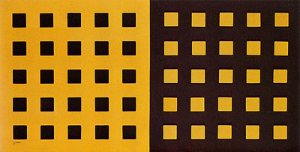
[i]Concreção 5732, 1957[/i][br]Luiz Sacilotto[br]Synthetic enamel on aluminum, c.i.e.[br]40.90 cm x 81.70 cm[br]Collection of the Museum of Contemporary Art of the University of São Paulo[br]Source: Enciclopédia Itaú Cultural.
Using the GeoGebra Translate command, reproduce part of the artwork [i]Concreção 5732[/i] following the steps below. The chosen part will be the one formed by black squares on a yellow background.[br][br][list=1][*]Open the GeoGebra online app by clicking on the link [url=https://www.geogebra.org/classic?lang=pt_PT]https://www.geogebra.org/classic[/url].[/*][*]Create a square ABCD ([i]q1[/i]) with one unit of side length.[/*][*]Remove the labels of the points, segments, and polygon. Hide the vertices A, B, C, and D of the square.[/*][*]Start by creating a vector [i]u[/i] indicating the horizontal direction and a vector [i]v[/i] indicating the vertical direction (remove the labels), both with the same length as the side of the original square.[/*][*]Using the [b]Translate[/b] command, create squares from the original square ABCD. For example, type q1_{2} = Translate(q1, 2u) in the input field of the Algebra menu. This command will represent the square A'B'C'D' obtained from the translation of square ABCD in the direction of [i]u[/i] and displaced by 2 units from the original square.[/*][*]Continue creating the other 3 squares, following the naming convention, and complete the first row of the artwork [i]Concreção 5732[/i].[/*][/list][br]Alternatively, instead of creating the first row square by square, you can create a button named "First Row." After creating this button and accessing the Configuration option, choose "Scripting" and, in the "On Click" tab, type all the squares to be obtained by translating ABCD in the direction of vector [i]u[/i].[br][code][br]q1_{2}=Translate(q1,2u)[br]q1_{3}=Translate(q1,4u)[br]q1_{4}=Translate(q1,6u)[br]q1_{5}=Translate(q1,8u)[/code]
What do you observe when clicking the "First Row" button in your activity?
All the squares in the first row are displayed instantly. These squares are the result of the translation of the original square ABCD in the direction of vector u, but with different distances.
To create the second row of squares, what could be a sequence of [b]Translate[/b] commands to be programmed in a new button? Consider the translation of the squares in the first row in the direction of the vector [i]v[/i] created initially.
Suggested sequence of commands:[br][br][code]q2_{1}=Translate(q1,2v)[br]q2_{2}=Translate(q1_{2},2v)[br]q2_{3}=Translate(q1_{3},2v)[br]q2_{4}=Translate(q1_{4},2v)[br]q2_{5}=Translate(q1_{5},2v)[/code][br][br]Note: The naming convention used may vary, but it is necessary to observe the dependence of the translated objects.
To create the third row of squares, what could be a sequence of commands to be programmed?
Suggested sequence of commands:[br][br][code]q3_{1} = Transladar(q1,4[i]v[/i])[br]q3_{2} = Transladar(q1_{2},4[i]v[/i])[br]q3_{3} = Transladar(q1_{3},4[i]v[/i])[br]q3_{4} = Transladar(q1_{4},4[i]v[/i])[br]q3_{5} = Transladar(q1_{5},4[i]v[/i])[/code][br][br]Note: The naming convention used may vary, but it is necessary to observe the dependence of the translated objects.
Create the last two rows of the first part of the artwork [i]Concreção[/i] with what you have learned about the [b]Translate[/b] command.
The second part of the artwork, that is, the yellow squares on a black background, can be obtained using which isometric transformation?
Justify the choice made in the previous question.
Reflection: The second part of the artwork can be obtained by reflecting the first part with respect to a vertical line.[br][br]Translation: Just like the squares on the left side, those on the right side can be obtained through translations.
In addition to the [b]Translate[/b] command, by using the [b]Reflection[/b] command, it was possible to create a reinterpretation of [i]Concreção 5732[/i]. Interact with the proposed activity, using the indicated buttons, and complete the creation of this reinterpretation by following these steps:[br][list=1][*]Create each row of black squares by clicking the [b]First Row[/b], [b]Second Row[/b], and so on.[/*][*]Create the symmetry axis of the artwork by clicking the [b]Symmetry Axis[/b] button.[/*][*]Reflect the background square by clicking [b]Reflection Background[/b], and then change the color so that the background becomes black. To do this, click the [b]Change Background Color[/b] button.[/*][*]Reflect each row created previously, always clicking [b]Change Color[/b] immediately after reflecting each row.[/*][/list][list][/list]
Return to the activity you were creating and, using the [b]Reflection[/b] command, try to complete your reinterpretation of the artwork [i]Concreção 5732[/i], since the right side of the artwork corresponds to the reflection of the first part, with alternating colors.[br][br]Suggested steps to follow:[br][br][list=1][*]To reflect each square you created, it will be necessary to create a line (line) that represents the axis of symmetry of the artwork. For example, using the [b]Reflect[/b] command, define [b]q'1_{1} = Reflect(q1, line)[/b] in the programming tab of the [b]Reflection q1[/b] button. The object thus defined, [b]q'1_{1}[/b], represents the reflection of square [b]q1[/b], present in the first row of squares of the artwork. By clicking the [b]Reflect q1[/b] button, you will be able to see the reflection of square [b]q1[/b] with respect to the line, with the same color as the original. Using a naming convention that identifies each square is important for organization.[/*][*]To change the color of objects in GeoGebra, you can also use GeoGebraScript commands like [b]SetColor[/b] or [b]SetBackgroundColor[/b]. In this activity, the command was inserted into the programming tab of the [b]Change Background Color[/b] button with the following command: [b]SetColor(POL', Black)[/b]. Here, [b]POL[/b] represents the larger yellow square on the left side of the artwork, and [b]POL'[/b] is the larger black square resulting from the reflection: [b]POL'=Reflect(POL,line)[/b]. Similarly, buttons were created to define the colors of other geometric objects present in the artwork.[/*][*]Try to organize your programming when reflecting objects. You can choose to reflect an entire row, such as in the following sequence of commands:[/*][/list][br][code]q'1_{2}=Reflect(q1_{2},line)[br]q'1_{3}=Reflect(q1_{3},line)[br]q'1_{4}=Reflect(q1_{4},line)[br]q'1_{5}=Reflect(q1_{5},line)[br]q'1_{1}=Reflect(q1,line)[br][/code][br]This sequence of commands was inserted into the programming of the [b]Reflection First Row[/b] button.